A FPGA Stereo Matching Algorithm Modeled By
DSP Builder
Xiang Zhang
State Key Laboratory of Fluid Power Transmission and Control, Zhejiang University, Hangzhou, China Email: [email protected]
Zhangwei Chen
State Key Laboratory of Fluid Power Transmission and Control, Zhejiang University, Hangzhou, China Email: [email protected]
Abstract—This paper proposes a System-on-Programmable-Chip (SoPC) architecture to implement a stereo matching algorithm based on the sum of absolute differences (SAD) in a FPGA chip which can provide 1396×1110 disparity maps at 30 fps speed. The hardware implementation involves a 32-bit Nios II microprocessor, memory interfaces and stereo matching algorithm circuit module. The stereo matching algorithm core is modeled by the Matlab-based DSP Builder. The system can process many different sizes of stereo pair images through a configuration interface. The maximum horizon resolution of stereo images is 2048.
Index Terms—Stereo matching, System-on-programmable-chip, FPGA, Disparity map, SAD, DSP Builder
I. INTRODUCTION
The stereo vision has been one of the most active research topics in computer vision and widely used in many application areas including intelligent robots, automated guided vehicle, human-computer interface, 3D scanner and so on[1-5]. Stereo matching algorithms have played an important role in stereo vision. They can be classified into either local or global methods of correspondence. Local methods match one window region centered at a pixel of interest in one image with a similar window region in the other image by searching along epipolar lines. The performance of local stereo matching algorithms depends to a large extent on what similarity metric is selected. Typical similarity metrics are cross-correlation (CC), the sum of absolute differences (SAD), the sum of squared differences (SSD), etc. SSD and SAD find correspondences by minimizing the sum of squared or that of absolute differences in W×W windows. The computational complexity for N×N resolution image pair, W×W window size and D disparity level is
(
2 2)
O N W D . It can be decreased to
( )
2O N D by
some kind of optimization tips [6]. So the stereo vision has limitations for real-time applications due to its computational expense.
Many researchers have proposed their FPGA implementations of stereo vision algorithms in literature.
The circuit [7] is a miniature stereovision machine (MSVM-III) with three cameras for generating high-resolution dense disparity maps at the video rate. The machine, running at 60 MHz could process more than 30 fps dense disparity maps with 640×480 pixels in 64-pixel disparity search range. The paper [8] proposes an architecture that solves the matching problem on 8-bit 512×512 stereo images by using the SAD as similarity metric. When realized using a XILINX Virtex4 XC4VLX15 device, the circuit computes a 512×512 disparity map, with a maximum disparity of 255 in 39ms. The paper [9] describes the implementation of a stereo depth measurement algorithm in hardware on Field-Programmable Gate Arrays (FPGAs). This system generates 8-bit sub-pixel disparities on 256×360 pixel images at video rate 30 fps. Gardel et al. propose a hardware implementation of a dense recovery of stereovision 3D measurements in paper [10]. Considering hardware FPGA clock of 100 MHz, image flows up to 50 frames per second of dense stereo maps of more than 30,000 depth points could be obtained considering 2 Mpix images. The paper [11] presents a binary fully adaptable window for incorporating in a stereo matching System-on-Chip (SoC) architecture. The design in [12] is a real-time stereo vision System-on-Chip (SoC) architecture for a depth-field generation processor as required in 3D TV applications. A real-time stereo matching calculation at a frame rate of 56 Hz with a resolution of 800×600 and a disparity of 80 has been realized using this architecture without the need for external memories. However, these designs rarely attain the target of producing above 720P resolution disparity map at real-time speed.
1396×1110 high-definition stereo images under 60MHz working frequency.
II. DSPBUILDER DESIGN FLOW
Digital signal processing (DSP) system design in programmable logic devices (PLDs) requires both high-level algorithm and hardware description language (HDL) development tools.
The Altera DSP Builder integrates these tools by combining the algorithm development, simulation, and verification capabilities of The MathWorks MATLAB and Simulink system-level design tools with VHDL and Verilog HDL design flows, including the Altera Quartus II software.
We can combine existing MATLAB functions and Simulink blocks with Altera DSP Builder blocks and Altera intellectual property (IP) MegaCore functions to link system-level design and implementation with DSP algorithm development. In this way, DSP Builder allows system, algorithm, and hardware designers to share a common development platform.
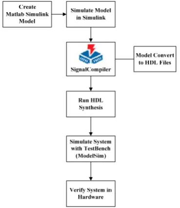
The DSP Builder Signal Compiler block reads Simulink Model Files (.mdl) that contain other DSP
Builder blocks and MegaCore functions. Signal Compiler then generates the VHDL files and Tcl scripts for synthesis, hardware implementation, and simulation. Fig. 1 shows the DSP Builder system-level design flow. The modules of our design mentioned in Section V are all modeled and simulated by MATLAB/Simulink.
Figure 1. DSP builder system-level design flow.
III. SOPC ARCHITECTURE FOR SAD MATCHING
ALGORITHM
The SoPC architecture proposed herein is divided into the following main modules as shown in Fig. 2:
(1) Microprocessor system: It consists of a 32-bit Nios II processor core, a set of chip peripherals, on-chip memory, and interfaces to off-on-chip memory.
(2) SAD Stereo Matching Unit (SSMU): This unit
computes sum of the absolute difference as similarity metrics to seek disparities from 64 candidates 5×5 windows. There are three Avalon-MM interfaces. One is slave interface to communicate with the Nios II CPU. The other two are read and write master interfaces. The read master is in charge of reading raw data of stereo images from the off-chip PSRAM acting as frame buffer in system. The write master takes charge of write final disparities to the DDRII.
(3) DDR Controller and PSRAM Controller: These two IPs are provided by Altera. They enable the system to access the DDRII and PSRAM memory out of the FPGA chip.
The modules listed above are all synthesized in one EP3C120 FPGA chip produced by Altera Company. They connect with each other by Avalon bus interface.
Figure 2. Proposed SoPC architecture.
IV. HARDWARE IMPLEMENTATION OF THE SSMU
The SAD equation used for 5×5 windows with a maximum disparity of 64 can be seen in equation (1):
2 2 R 2 2
P
SAD( )
P
h k L
( i h, j k )
i, j,disp .
( i h, j k disp )
=− =−
+ +
=
− + + +
∑ ∑
(1)Where disp is the disparity value ranging from 0 to 63, PR(i, j) serves as the reference pixel in the right image
and PL(i, j+disp) as the currently analyzed candidate
pixel in the left image.
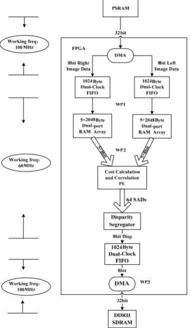
or left image in turn and it almost consumes 27 clocks. So under the working frequency of 100MHz, the DMA engine can offer about 113MB per second data bandwidth. It is enough for 2×1396×1110@30fps needs.
Figure 4. Layout plan of the SSMU module
The two dual-clock FIFOs (DCFIFO), followed by the DMA engine, have two functions. One is temporary storage for the raw pixel data. The other is separating the workspace into two regions which work under different working frequency. At the writing and reading side of the FIFO, the working frequency is 100MHz and 60MHz respectively.
Beside the read side of the DCFIFO is a dual-port RAM (DPRAM) array which is constituted by 5 DPRAMs, each with 2048 byte of memory space. They are used as line buffers for cost calculation and correlation processing element (CCCPE). Every
DPRAM has data bus connected with CCCPE; therefore every DPRAM array can output 5 bytes of image data to the CCCPE in every clock cycle.
The CCCPE is the most complex hardware circuits in the SSMU. As shown in Fig. 5, there are 64 SAD computers and 2 shift-tap devices in the CCCPE. The 2 shift-tap devices have 25 and 340 shift registers respectively to store the pixel data participated in computation of the SADs. One SAD computer can sum 25 absolute differences up which are produced by two 5×5 matching windows in a clock-period. Therefore, the
CCCPE module can achieve 64 SADs from a template
window in the right census image compared with 64 candidate windows in the left census image in a single clock. Fig. 6 is the block diagram of the SAD computers. The SAD computer is constituted with 25 absolute difference calculators (AD) and a parallel adder with 25 inputs. The parallel adder has 4 pipelined stages architecture for improving the fmax.
The 64 SADs produced by CCCPE are sent to the disparity segregator (DS). The DS calculates the minimum SAD using parallel comparators from 64 SADs and outputs the index number as the disparity, and the cost time is one clock period. Fig. 7 is the block diagram of the disparity segregator. The final disparities are push into the DCFIFO connected with DS module. The DCFIFO’s function in here is similar with the one mentioned in previous. A custom DMA engine followed with read port of the DCFIFO is responsible for writing the final disparities to the disparity table stored in the off-chip DDRII SDRAM. To fully using of the bandwidth, the DMA engine compresses four 8-bit disparities into a 32-bit word and transfers it to the off-chip DDRII SDRAM.
Figure 5. Layout plan of the SSMU module.
Figure 7. Block diagram of the disparity segregator.
V. DSP BUILDER MODELS OF THE SSMU
A. Model of the Absolute Difference (AD) Computer As shown in Fig. 8, the absolute difference computer is composed of one if statement, two multiplexers and one two 8-bit width inputs adder. It can output the absolute difference of two input data.
Figure 8. Model of the absolute difference computer.
B. Model of the SAD Computer
The model of the SAD computer, as shown in Fig. 9, has 25 AD computers and a parallel adder with 25 9-bit width input ports. The parallel adder is fed 25 AD values from 25 AD computers and outputs a 15-bit SAD value within 4 clocks delay.
Figure 9. Model of the SAD computer.
C. Model of the 64 SAD Computers Array
The 64 SAD computers array is made of 64 SAD computers, 365 input ports and 64 output ports. In this model, the SAD computers are placed in subsystem style shown in Fig. 10. The chart of this model is too large to fit in the paper, so we don't put the chart here.
Figure 10. Model of the SAD computer in subsystem style
D. Model of the Basic Comparison Element
The basic comparison element (BCE) compares two input SAD values and produces a comparison bit served as a select signal for a multiplexer. The multiplexer outputs the minimum SAD involved in the comparison in the next stage.
Figure 11. Model of the basic comparison element.
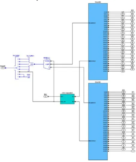
E. The Top Level Model of the Disparity Segregator The disparity segregator is made of 63 BCEs. The two blue blocks in Fig. 12 are subsystem modules involving 31 BCEs each. The DS module can segregate minimum SAD from 64 input values.
Figure 12. The top model of the disparity segregator.
VI. RESULTS AND DISCUSSION
Figure 13. The Cyclone III development board.
Table I shows the resources required from the FPGA device in order to implement the designs presented in this paper. The report is produced by the Quartus II v12.0SP2 edition.
TABLE I.
RESOURCES NEEDED FOR THE PROPOSED SYSTEM
Device
Altera EP3C120F780C7N (Cyclone III device family) Resource
Total logic elements 93242 / 119088 (78%) Total combinational functions 86012/ 119088 (72%) Dedicated logic registers 46765 / 119088 (39%) Total registers 46994
Total pins 151 / 532 (28%) Total memory bits 448296 / 3981312 (12%) Embedded Multiplier 9-bit elements 12 / 576 (2%) Total PLLs 2 / 4 (50%)
The quality measures proposed by [13] are based on known ground truth data d (x, y)T offered by Middlebury Stereo datasets used for evaluation. The percentage of bad matching pixels is computed with respect to some error toleranceδd:
,
1
M (| ( , ) ( , ) | ).
N c T d
x y
d x y d x y δ
=
∑
− > (2)where d (x, y)c is disparity map produced by the proposed
hardware .
The ground truth image has disparity range from 0 to 59. The disparity range of our design is 0 to 63. So a disparity error tolerance δd= 1 to 4 is used. The measures are computed over the whole disparity map, excluding image borders, where part of the image is totally occluded.
Several tests have been performed. In Fig. 14, the produced disparity maps are showed. In Table II , the bad pixel rates are listed. Disparities are all encoded using a scale factor of 4 for gray levels 0 to 252.
(a) (b) (c)
(a): The original right image. (b): The ground truth image. (c): The produced depth map.
Figure 14. Evaluation result produced by the proposed system using Middlebury stereo images.
TABLE II.
BAD PIXEL RATE OF THE EVALUATION RESULTS
d
δ Cone Teddy Baby Venus
1 24.67% 23.2% 28.25% 17.25% 2 21.53% 20.48% 26.44% 14.97% 3 18.73% 18.54% 25% 13.16% 4 16.51% 17.12% 23.66% 11.54%
In Table III, the proposed system is compared to the existing approaches in terms of speed.
TABLE III.
SPEED COMPARISON OF THE STEREO MATCHING IMPLEMENTATIONS
Authors
Index
Motten et al. [12]
Proposed
Imple. Kalomiroset al. [15]
Niitsuma et al. [14]
Frame
Rate 56fps 30fps 162fps 30fps
Images
Size 800
×
600 1396×
1110 640×
480 640×
480 MaxDisparity 80 64 64 27
Algorithm SAD SAD SAD SAD
Windows
Size 7
×
7 5×
5 3×
3 7×
7Hardware
Platform 1 FPGA 1 FPGA 1FPGA+ PC 1 FPGA
VII. CONCLUSIONS/OUTLOOK
ACKNOWLEDGMENT
This work has been cooperatively supported by the projects as follows:
1. National natural science foundation of China (61202093).
2. 3D innovation team of Zhejiang provincial.
REFERENCES
[1] M. Bertozzi, A. Broggi, "GOLD: A Parallel Real-time
Stereo Vision System for Generic Obstacle and Lane Detection," IEEE Transactions on Image Process, vol. 7(1) (1998), pp. 62-81.
[2] N. Uchida, T. Shibahara, T. Aoki, H. Nakajima, K. Kobayashi, "3-D Face Recognition Using Passive stereo vision," Proceedings of IEEE International Conference on Image Process (2005), pp. 950-953.
[3] A. Bensrhair, M. Bertozzi, A. Broggi, A. Fascioli, S. Mousset, G. Toulminet, "Stereo Vision-based Feature Extraction for Vehicle Detection," in: IEEE Intelligent Vehicle Symposium 2 (2002) , pp. 465-470.
[4] Zhihua Lv, Zhiyi Zhang, "Build 3D Scanner System based on Binocular Stereo Vision," Journal of Computers, vol. 7(2) (2012), pp. 399-404.
[5] Zetao Jiang, Yanru Cuo, Qiang Wang, "A New Obstacle Avoidance Method Based on Biped Robot," Journal of Computers, vol. 7(10) (2012), pp. 2362-2367.
[6] M. Z. Brown, D. Burschka, G. D. Hager, "Advances in Computational Stereo," IEEE Transactions on Pattern Analysis and Machine Intelligence 25 (8) (2003) 993-1008. [7] Yunde Jia, Xiaoxun Zhang, Mingxiang Li, Luping An, “A Miniature Stereo Vision Machine (MSVM-III) for Dense Disparity Mapping,” Proceeding of the 17th International Conference on Pattern Recognition (2004), pp. 728-731. [8] Perri, S., Colonna, D., Zicari, P., Corsonello, P.,
"SAD-Based Stereo Matching Circuit for FPGAs," In Proceedings of the 13th IEEE International Conference on Electronics, Circuits and Systems, Nice, France, 10–13 December 2006; pp. 846–849.
[9] Darabiha, A., Rose, J., MacLean, W.J., "Video-Rate Stereo Depth Measurement on Programmable Hardware," In Proceedings of the 2003 IEEE Computer Society Conference on Computer Vision and Pattern Recognition, Madison, WI, USA, 18–20 June 2003; pp. 203–210. [10] Gardel, A., Montejo, P., Garcia, J., Bravo, I., Lázaro, J.,
"Parametric dense stereovision implementation on a System-on-Chip (SoC)," Sensors 2012, 12, 1863–1884. [11] Andy M., Luc C., "A Binary Adaptable Window SoC
Architecture for a Stereo Vision Based Depth Field
Proccssor," VLSI System on Chip Conference (2010), pp. 25–30.
[12] Motten, A., Claesen, L., "Low-Cost Real-Time Stereo Vision Hardware with Binary Confidence Metric and Disparity Refinement," In Proceedings of the 2011 International Conference on Multimedia Technology, Hangzhou, China, 26–28 July 2011; pp. 3559–3562. [13] Scharstein D, et al., "A Taxonomy and Evaluation of Dense
Two-frame Stereo Correspondence Algorithms," International Journal of Computer Vision 47( 2002) 7-42. [14] Ambrosch, K., Humenberger, M., Kubinger, W., Steininger,
A., "Hardware Implement of an SAD Based Stereo Vision Algorithm," In Proceedings of the IEEE Conference on Computer Vision and Pattern Recognition, Minneapolis, MN, USA, 17–22 June 2007; pp. 1–6.
[15] Kalomiros, J., Lygouras, J., "Comparative study of local SAD and Dynamic Programming for Stereo Processing using Dedicated Hardware," EURASIP J. Adv. Signal Process. 2009.
Xiang Zhang received B.S. and M.S.
degree in computer science from Hangzhou Dianzi University, Hangzhou City, China, in 2001 and 2004, respectively. He is currently working toward a Ph.D. degree with the state key laboratory of fluid power transmission and control, Zhejiang University. His research interests include computer vision, image parallel processing, embedded systems, and real-time applications.
Zhangwei Chen, born in March 1965,