ISSN (Online): 2320-9364, ISSN (Print): 2320-9356
www.ijres.org Volume 3 Issue 9
ǁ
September. 2015
ǁ
PP.41-47
Unit Power Factor Servo Drive Control System
Yudan Huang, Guohui Zeng
School of Electronic and Electrical Engineering, Shanghai University of Engineering Science, Shanghai, China
School of Electronic and Electrical Engineering, Shanghai University of Engineering Science, Shanghai, China
Abstract
: In order to solve the problem that the load of the servo drive system can easily lead to the decrease of the power grid’s power factor and generate the harmonic pollution, in this paper, single-phase PWM rectifieris applied to servo drive control system. In the design of single-phase PWM rectifier, the double closed-loop
control strategy of current voltage and the virtual phase lock technology are applied to make the power grid
side current sinusoidal and track the phase of the power grid side voltage to achieve unity power factor control.
In the servo motor control, the maximum current torque ratio control strategy is used. PWM rectifier as the
servo drive control system front, for its energy. And build a simulation model in MATLAB, through the
simulation analysis, it is verified that this method can realize the control of the grid side unity power factor, and
the servo drive system is robust.
Keywords
- single phase PWM rectifier, PMSM, MATLABI.
INTRODUCTION
With the development of industrial production, servo drive systems are more widely used. Because of its
fast reaction speed and good stability, permanent magnet synchronous motor has been widely used in servo
drive system. However, the permanent magnet synchronous motor is a kind of nonlinear resistive load. In the
process of using, the reactive power will be generated and transmitted to the power grid, which will reduce the
power factor of the grid side. For such problems, with the single-phase PWM rectifier provides permanent
magnet synchronous motor servo drive system’s energy, to reduce the reactive power transmission to the power
grid from servo drive system, and to achieve unity power factor in power grid side. In this paper, in order to
design PWM rectifier, the virtual three-phase technique is applied to the voltage and current double closed-loop
control mode, and combining the PWM rectifier and servo motor vector control system together, to establish
simulation model in MATLAB, through the simulation model to verify the reliability and validity of the method.
II.
SINGLE-PHASE
PWM
RECTIFIER
DESGN
2.1 Mathematical model of single-phase PWM Rectifier
The switch is considered as the idealized switch model, and the simplified model of the main circuit of
Fig.1 Simplified model of single phase PWM rectifier’ main circuit
When 𝑠1 is on,𝑠2 is off,𝑠𝑎 = 1; When𝑠1 is off, 𝑠2 is on𝑠𝑎 = 0; When𝑠3 is on,𝑠4is off,𝑠𝑏= 1; When 𝑠3
is off,𝑠4is on, 𝑠𝑏 = 0;then:
𝑢𝑎𝑏 =
𝑢𝑑𝑐
0 −𝑢𝑑𝑐
(1)
Where 𝑢𝑎𝑏 is the grid side voltage;𝑢𝑑𝑐 is the DC side voltage;𝑠𝑎 and 𝑠𝑏 are the conditions of the two
bridges, and when the upper bridge is on, then it is compared to 1,otherwise it is compared to 0. Simplified
equation (1) can get:
𝑢𝑎𝑏 = (𝑠𝑎− 𝑠𝑏)𝑢𝑑𝑐 (2)
From the equation (2), it can be obtained more simplified AC side circuit model, as shown in Figure 2.
Fig.2 Simplified circuit model of AC side for single phase PWM rectifier
By Kirchhoff's law can get:
𝑢𝑠= 𝐿𝑑𝑖𝑑𝑡𝑠+ 𝑢𝑎𝑏(3)
The power balance principle can be got when the switch loss is neglected:
𝑢𝑠𝑖𝑠= 𝑢𝑑𝑐𝑖𝑜 (4) Where𝑖𝑜 is output current, and:
𝑖𝑜= (𝑠𝑎− 𝑠𝑏)𝑖𝑠(5) In the DC side can get:
𝑖𝑜= 𝐶𝑑𝑢𝑑𝑡𝑑𝑐+𝑢𝑅𝑑𝑐(6)
Combined all equation of above can get:
𝐿𝑑𝑖𝑠
𝑑𝑡 = 𝑢𝑠− (𝑠𝑎− 𝑠𝑏)𝑢𝑑𝑐
𝐶𝑑𝑢𝑑𝑐
𝑑𝑡 = 𝑠𝑎− 𝑠𝑏 𝑖𝑠− 𝑢𝑑𝑐
2.2 Controller design for single phase PWM rectifier
In the single-phase PWM controller design, aimed at stabilizing the DC voltage in the DC side and realize
unity power factor in the grid side.In this paper, the virtual three-phase technology is applied to the voltage
current double closed-loop control mode, in order to constitute the control system of PWM rectifier.
2.2.1 Voltage-Current double closed-loop control
In the design of PWM rectifier controller, the voltage loop is used as the outer loop and compared with the
reference value of voltage. Then get the voltage error signal and as the input signal of proportional integral regulator. The output of the regulator is the magnitude of the current command, and use the regulator’s output signal multiply the sinusoidal signal can get the current command.The current instruction value is adjusted in the
inner loop of the current regulation, and then compared with the sine wave, so that the corresponding modulated
wave is obtained.Through the SPWM algorithm, it can achieve the expected control target.Current voltage
double closed-loop control block is shown in Fig.3:
Fig.3 Voltage-Current double closed-loop control block diagram
In Fig.3,𝑢𝑑𝑐∗ is the voltage command value; θis the voltage phase of power grid; 𝑖𝑠 is the current of grid
side.
2.2.2 Virtual three-phase technology
Phase locked loop (PLL) is a kind of phase feedback control system can not only realization of constant
frequency signal tracking control, and changes in the frequency of signal has higher tracking accuracy and
sensitivity.In this paper, the virtual three-phase technology is used to construct the single phase current into the
virtual three-phase current.The method of single synchronous rotating coordinate system phase locked loop is
used to realize synchronous tracking of the current to the voltage.Control system block as shown in Fig.4:
Fig.4 The block diagram of the virtual three-phase technology PLL
In Fig.4,𝑖𝑠 is the current of grid side;ω is the grid angular frequency;θ is the voltage phase of power grid.
First, the grid side current lags 1/6 period, then reverse, then get the current that phase-lead 120 degrees of grid
side current𝑖𝑠.And use the lags 1/6 period’s current subtract grid side current 𝑖𝑠 can get the current that
phase-lags 120 degree of grid side current 𝑖𝑠. Thus, the single-phase current is constructed into the virtual
three-phase current. And applied it to the single synchronous coordinate system PLL. Then get 𝑖𝑑 and 𝑖𝑞
phase lock, and the synchronization of the current and the voltage phase of the power grid is realized. The
virtual three-phase technology is applied to the voltage current double closed-loop control system can get the
system control block diagram as shown in Fig.5:
Fig.5 Virtual three-phase technology applied to the voltage-Current double closed-loop control
The virtual three-phase technology is applied to the voltage current double closed-loop control strategy of
single-phase PWM rectifier control system block shown in Fig.6:
Fig.6 Control system block diagram of single phase PWM rectifier
III.
PMSM
VECTOR CONTROL SYSTEM DESIGN3.1 PMSM mathematical model
In this paper, the permanent magnet synchronous motor is SPMSM, that is:𝐿𝑑 = 𝐿𝑞, and use with maximum
torque current ratio control strategy, that is:𝑖𝑑 = 0,so the mathematical model of permanent magnet synchronous
motor can be turned into:
𝑢𝑑 = −𝜔𝑟𝐿𝑞𝑖𝑞
𝑢𝑞= 𝐿𝑞 𝑑𝑖𝑞
𝑑𝑡 + 𝑅𝑠𝑖𝑞+ 𝑒
𝑇𝑒 =32𝑝𝜑𝑓𝑖𝑞
𝑇𝑒 = 𝐽𝑑𝜔𝑑𝑡𝑟+ 𝐵𝜔𝑟+ 𝑇𝐿
(8)
Where 𝑢𝑑 and 𝑢𝑞 are the d- and q-axis voltage, respectively;𝑖𝑑 and𝑖𝑞 are the d- and q-axis stator current,
respectively;𝜔𝑟 is the rotor mechanical speed;𝐿𝑑 and 𝐿𝑞 are the d- and q-axis inductance;𝑅𝑠 is the winding
stator resistance;𝜑𝑓 is the permanent-magnet flux linkage;e is the counter electromotive force;𝑇𝑒 is the
electromagnetic torque;B is the viscous friction coefficient;𝑇𝐿 is the load torque; and p is the number of pole
pairs.
3.2 PMSM vector control system design
By the maximum torque current ratio of the control strategy, the block diagram of the PMSM vector control
Fig.7 PMSM vector control system block diagram
IV.
SINGLE PHASEPWM
RECTIFIER SERVO DRIVE CONTROL SYSTEM DESIGNFrom the first two sections of this paper, a mathematical model of single-phase PWM rectifier and PMSM
is obtained.In the single-phase PWM rectifier, the control strategy of the combination of the virtual three-phase
technology and the voltage current double closed-loop is adopted, and the maximum current torque ratio control
for PMSM is adopted. Therefore, the single phase PWM rectifier servo drive control system block diagram is
shown in Fig.8:
Fig.8 Servo drive control system for single phase PWM rectifier
V.
SIMULIATION
ANALYSIS
The simulation model of the servo drive control system of single phase PWM rectifier in MATLAB is
establis5hed by figure 8.
The parameters of single-phase PWM rectifier are as follows:
𝑢𝑠= 220𝑉;f = 50Hz;L = 5mH;C = 600μf;𝑅𝑑 = 51𝛺;𝑢𝑑𝑐 = 450𝑉. PMSM parameters are as follows:
2.875Ω
R
s
;𝜑𝑓 = 0.175𝑤𝑏;L
d
L
q
8.5mh
;p
2
;J
0.01kg
m
2
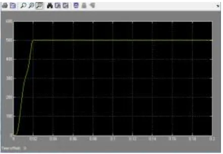
;n = 500n/min.Fig.9 grid side voltage and current waveformFig.10 Grid side input active and reactive power
Fig.11 Grid side power factorFig.12 Rectifier output DC voltage
Fig.13 Permanent magnet synchronous motor speed
In Fig.9,it is the waveforms of grid voltage and current. From thisfigure, after 0.02s, the grid side current
and voltage phase almost simultaneously;In Fig.10, the red line indicates reactive power, yellow line is active
power.Obtained from the figure, after the 0.035s and grid side of the rectifier’s reactive power and active power
are stability, and the grid side without reactive power. In Fig.11,it is the waveform of power fact.After 0.035s,
the grid side power factor of the rectifier is equal to one.By Fig.9, fig.10 and fig.11, the rectifier can achieve the
grid side unity power factor.
Fig. 12 shows the rectifier output DC voltage, when the rectifier is stable, the output DC voltage is stable at
the DC voltage setting 450V.Fig.13 shows the speed of the permanent magnet synchronous motor in the servo
drive control system, After 0.02s, the motor speed is stable at the speed setting 500n/s.
Through the above analysis,the servo drive system controlled by single phase PWM rectifier can realize
VI.
CONCLUSION
In this paper, the energy source of the single phase PWM rectifier is used as the servo drive system,the
voltage current double closed-loop control is adopted to single phase PWM rectifier, and the virtual three-phase
technology is applied to double closed-loop control,in order to achieve the sinusoidal input current and to
achieve the same phase of the input current and input voltage.Maximum torque current ratio control strategy is
used to permanent magnet synchronous motor’s vector control system, and build simulation model in MATLB.
By simulation, this method can make the input current sinusoidal, and make input current and input voltage have
the same phase.Through the PWM rectifier with unity power factor control, can greatly reduce the reactive
power which produced by Servo drive system transmitted to the power grid, and improve power quality of
power grid.At the same time, it can make the servo drive system run stably.
VII.
A
CKNOWLEDGEMENTSFirst of all, I would like to extend my sincere gratitude to my supervisor: ZENGGuohui, for hisinstructive a
dvice and useful suggestions on my thesis. I am deeply grateful of his help in the completion of this thesis. Also
I would like to express my gratitude to my project team members, they gave me much help, and whenever I
encounter difficulties, they always encourage me.
At the same time, this work is supported by the Innovation foundation of SUES under Grant
N0.E1-0903-15-01026
REFERENCES
[1] R. Kennel and P. Szczupak, ―Sensorless control of 3-phase PWM rectifier,‖ in Proc. 31th Annu. IEEE IECON, Nov. 2005, pp.
1–6.
[2] J. Kolar and T. Friedli, ―The essence of three-phase PFC rectifier systems—Part I,‖ IEEE Trans. Power Electron., vol. 28, no. 1,
pp. 176–198, Jan. 2013
[3] L. Pereira, J. Vieira, G. Bonan, D. Coutinho, and J. da Silva, ―Multipleresonant controllers for uninterruptible power supplies—A systematicrobust control design approach,‖ IEEE Trans. Ind. Electron., vol. 61, no. 3,pp. 1528–1538, Mar. 2014.
[4] P.Sergeant, F. De Belie, and J. Melkebeek, ―Rotor geometry design of interior PMSMS with and without flux barriers for more
accurate sensor less control,‖ IEEE Trans. Ind. Electron., vol. 59, no. 6, pp. 2457–2465,Jun. 2012.
[5] Y. Zhang et al., ―Performance improvement of direct power control ofPWM rectifier with simple calculation,‖ IEEE Trans.
Power Electron,vol. 28, no. 7, pp. 3428–3437, Jul. 2013.
[6] M. Angulo, D. Ruiz-Caballero, J. Lago, M. Heldwein, and S. Mussa,―Active power filter control strategy with implicit
closed-loop currentcontrol and resonant controller,‖ IEEE Trans. Ind. Electron., vol. 60, no. 7,pp. 2721–2730, Jul. 2013.
[7] G. Pellegrino, A. Vagati, P. Guglielmi, and B. Boazzo, ―Performance comparison between surface-mounted and interior PM Motor drives for electric vehicle application,‖ IEEE Trans. Ind. Electron., vol. 59, no. 2,pp. 803–811, Feb. 2012.
[8] Accetta, M. Cirrincione, M. Pucci, and G. Vitale, ―Sensorless control of PMSM fractional horsepower drives by signal injection