Study of Computer-Aided Design Process and
Methods Based on Welding Fixture
Yi Zhang
School of software engineering, Chongqing University, Chongqing, P. R. China Email: [email protected]
Sihui Mu
Chongqing Aerospace college of Vocational Technology, Chongqing, P. R. China Email: [email protected]
Abstract—Although various computer-aided fixture design (CAFD) systems have been developed to assist the designer during the various stages of fixture design, most of previous computer aided fixture design research has mainly concentrated on machining fixtures rather than welding fixtures. The development of complicated computer aided welding fixture design (CAWFD) system has received much less attention. Welding fixture can ensure welding dimension, improve assembly precision and efficiency. It can prevent the welding deformation. The function of welding fixture was introduced in this paper. The computer-aided welding fixture design workflow was developed. The design steps include the project creation, setup design, Orientation and position determination, fixture plan design, fixture configuration design, fixture design verification and fixture design output. The classification of welding fixture component has been demonstrated. Information tree and the database tables to save the unit information are designed. The unit information retrieval menu and interface based on UG, Visual C++ and database is realized.
Index Terms—Welding fixture, Computer-aided design, Database, UG, Visual C++
I. INTRODUCTION
A fixture is a device used in machining, inspection, assembly, welding, and other manufacturing operations to locate and hold a work piece firmly in position so that the required manufacturing processes can be carried out corresponding to design specifications. As a special kind of fixtures, welding fixtures are used wildly in many manufacturing fields. In welding industry, a welding fixture is a fixture used to ensure welding dimension, improve assembly precision and efficiency and to prevent the welding deformation. Hundreds of kinds welding fixtures have been designed and built to meet with various requirements during welding for different geometric work-pieces. According to statistics, about 73% of variation problems from preproduction to the production phase were caused by fixture related problems [1]. To improve the situation, it is of great importance to develop a fixture scheme with less sensitivity to control variables and noise effects. Therefore, in-depth research on quality design of fixture planning for flexible sheet metal assembly is highly desired [2].
Welding fixture design should meet the following requirements:
1) Welding fixture should meet the requirements of precision of processes. Although welding processes do not need the high accuracy, welding accuracy cannot be ignored.
2) Welding fixture should achieve the requirement of processing productivity. Especially for mass production of fixture, it should be used to shorten the basic and auxiliary processing time.
3) The generalization and standardization of the fixture element should be improved appropriately. To choose standard components, especially the commercialization of standard components, will shorten the fixtures manufacturing period, lower the cost of fixture. All these requirements build up the complexity of designing a suitable fixture.
As a part of manufacturing tooling, fixture design and related activities make significant contributions to the production time and cost in daily production. To help fixture designer and fixture manufacturer, a computer aided design system become importantly necessary immediately. Manufacturers need an assistant to design or choose fixtures as soon as possible. Collection and representation of the knowledge from the designer’s experience is crucial part in the development of computer-aided welding fixture design (CAWFD) systems. Computer aided welding fixture design (CAWFD) is a subsystem combining CAD and CAM. Software engineering and database technology assist designers to do welding fixture design and improve design efficiency [3-6].
II. PROCESS OF COMPUTER AIDED WELDING FIXTURE DESIGN SYSTEM
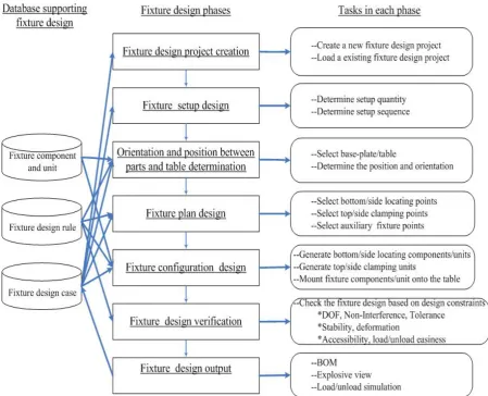
A. Computer-aided welding fixture design workflow and step
Figure 1 Computer-aided welding fixture design workflow
1) Project creation
A welding fixture design project is created from scratch. A saved fixture design project is reloaded, or searched from fixture design case base. A similar fixture design case is retrieved based on current user requirements including part CAD model and welding operation file. The retrieved fixture design is loaded.
2)Setup design
The setup quantity and sequence are determined in this phase.
3)Orientation and position determination
In this phase, parts to be welded in the setup will be loaded and assembled as a subassembly. Based on the overall dimension of subassembly, suitable welding table will be selected.
4)Fixture plan design
Based on well known 3-2-1 locating principle and other locating principles [3] stored in the design rule database, bottom locating points and side locating points should be selected to constrain six degree of freedom for each part . After locating point selection is done, associated top clamping points and side clamping points should be determined to keep the subassembly to contact
with the locating units and the stability should not be ruined. The rules on how to select the clamping points according to the existing locating points are also saved in the design rule database. For a complicated subassembly, the auxiliary locating points should be selected to keep the stability and avoid deformation.
5)Fixture configuration design
After the fixture points are selected, the coordinate values of each point will be calculated. The candidate fixture units will be retrieved by searching from fixture component or unit database and matching the type and values of fixture function attributes of fixture components or units with the type and coordinate values of the fixture point. The candidate fixture components and units will be listed according to the priority. Fixture designer can select any candidate from the list. The selected candidate fixture component or unit will be mounted on the table and kept contact with parts. The hole alignment between fixture component and unit and table will be realized.
6)Fixture design verification
freedom of the part should be limited. When the fixture components or units are loaded, there should not exist interference between fixture components or units and parts, between any one fixture component or unit and another fixture component or unit. The overall dimension of assembly to be welding should be satisfied. The stability of assembly should be kept, which means the assembly can not move and rotate during the welding process. The deformation of assembly should be controlled in an accepted level. The welding points or sews should be assessable to welding gun after the fixture components or units are loaded. The parts, fixture components or units should be moved in or removed out without difficulty.
7)Fixture design Output
Bill of Materials(BOM) , explosive view , and load or unload view should be output. Bill of Materials is the term used to describe the raw materials, sub-assemblies, intermediate assemblies, sub-components, components, parts and the quantities of each needed to manufacture an end item . For CAWFD, the quantities of parts to be welded and different kinds of fixture components used are listed in the BOM. In explosive view, all the parts to be welded, welding tables, fixture components in the whole assembly will be exploded. And the relationship among them will be shown clearly. In load or unload view, the load or unload sequence of parts to be welded, welding table, fixture units will be simulated. The interference during load or unload will be detected.
B. Analysis and classification of welding fixture component
Welding fixture is composed by a group of components. Each component has its unique function. So we put function as our last principle of classification. We use the geometrical shape and number to carry on the preliminary classification. We classified welding fixtures into seven groups [11-12].
The name of seven classifications of units are: 1) one table leg with one angle frontally;2) one table leg with one and angles frontally;3) one table leg with one angle laterally;4) one side clamping; 5) 0ne and side clamping; 6) point locating; 7) others, which is shown as table 1.
The unit of 1) or 2) is mainly a bottom locator when it is put in vertical direction. Work piece is located on the cantilever of the angle. If work piece is located at the end of the cantilever of the angle, it is a side locator. In a horizontal direction, it is also a side locater when we use the cantilever to locate the side of a work piece. The unit of 2) can set relative position of different parts of the work piece.
The unit of 3) is a bottom locator when work piece is located on the cantilever of the angle or block, or side locator when work piece is located at the end of them. It leaves space to the work piece in front of the table leg. The second unit in 3) is mainly a bottom locator, and its support can locate a side of the work piece. The third unit in 3) is mainly a side locator.
The units in group 4) are much simple for they just clamp one side.
The only one unit of group 5) locates the work piece at one side and clamps the opposite side. Though we have one unit here, more units will be found and classified into this group by the successors.
In the units of group 6), the stop can be put both in the vertical direction as a bottom point locater and in horizontal direction as a side point locater. The supports are in the horizontal direction and vertical direction, respectively.
TABLE I.
CLASSIFICATION OF WELDING FIXTURE COMPONENT
group figure
①
table leg with 1 angle frontally
②
table leg with 1+ angles frontally
③
table leg with 1 angle laterally
④
side clamping
⑤
side clamping
⑥
point locating
⑦
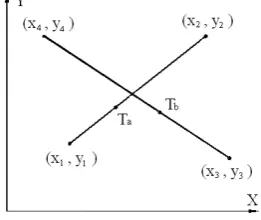
Figure 2 A line segment
Figure 3 Intersection of two line segments
Figure 4 Intersection of line and arc In group 7), the units have more than one function in
the same time. It can locate both bottom surface and side surface.
C. Analysis of interference checking between welding fixture components
Interference checking between fixture components is one of the important performances of welding fixture design. Once the fixture configuration design is generated with computer aided welding fixture design, interference checking should be employed. A rapid interference checking algorithm is studied for detecting possible interference between fixture components. In order to simplify the algorithm of interference checking, the fixture components need to be modeled. After the simplifications, fixture component models are 2-D geometric elements with certain heights.
1) Intersection detection of two line segments.
In general, the intersection of two line segments can be determined by examining the line equations. When a line is defined by two points [x1,y1] and [x2,y2], as shown in
Fig. 2, the coordinates of point on the line can be expressed as[13]
x a = x1 + Ta (x2 - x1) (1)
y a = y1 + Ta (y2 - y1) (2)
where Ta is a coefficient with a value 0≤Ta≤1.
When Ta is changed from 0 to 1, the point [xa,ya]
moves on the line segment from one end to the other. Thus, if Ta< 0 or Ta>1, xa and ya will extend beyond the
segment.
If the intersection occurs between two lines and the second line is defined by point [x3,y3] and [x4,y4], as
shown in Fig. 3, the intersection point becomes
xa = xb and ya = yb (3)
then
x1 + Ta (x2 - x1) = x3 + Ta (x4 – x3) (4)
y1 + Ta (y2 - y1) = y3 + Ta (y4 – y3 ) (5)
Finally, the solution of these simultaneous equations is
3 1 4 3 3 1 4 3
2 1 4 3 2 1 4 3
( )( ) ( )( )
( )( ) ( )( )
a
x x y y y y x x
T
x x y y y y x x
− − − + − −
=
− − − + − − (6)
2 1 3 1 2 1 3 1
2 1 4 3 2 1 4 3
( )( ) ( )( )
( )( ) ( )( )
b
x x y y y y x x
T
x x y y y y x x
− − − + − −
=
− − − + − − (7)
If the denominator of the expression defining Ta and Tb is zero, the lines are parallel. Hence, they do not intersect. If a solution is found when 0≤Ta≤1 and 0≤Tb ≤1, the segments intersect. Once Ta and Tb are obtained under the intersection condition, the intersection position can be figured out by solving xa and ya.
2) Intersection detection of a line segment and an arc. An arbitrary points on an are with radius R and center (xa,ya) can be defined as
cos
a c
x =x +R θ (8) sin
a c
y =y +R θ (9)
where the angular range of the arc is (θ1,θ2), as shown
in Fig. 4. If an intersection of the arc occurs with a line segment, we have
1 2 1) a c cos
x +(x −x T =x +R θ (10)
1 2 1) a c sin
y +(y −y T = y +R θ (11)
Rearranging the terms to cancel θ,
1 2 1
( ) ( )
cos
R
c a
x x T x x
θ = − + − (12)
1 2 1
( ) ( )
sin
R
c a
y y T y y
θ = − + − (13) and sin2
θ
+cos2θ
=1. This equation can be rewrittenas a quadratic function,
2
A t +B t + C = 0 (14) where the constant A, B, and C are defined as
2 2
2 1 2 1
A = (x −x) +(y −y) (15)
1 2 1 1 2 1
B = 2(x −xc)(x −x ) 2(+ y −yc)(y −y ) (16)
2 2
1 1
C = (x −xc) +(y −yc) −R (17) and =B - 4AC2
Δ . If Δ<0, there is no intersection between the line and circle. If Δ =0, the line is tangent to the circle. Then, one solution is obtained from the equation.
B T
2A
a = − (18)
Component
maintenance generation Unit unit output Candidate
Welding fixture component db
Welding fixture relationship db
Welding fixture unit db DB sub-system
Setup planning
Fixture point layout design
Fixture configuration
design
Interface and framework sub-system
Fixture design verification Point type
Acting height Candidate units
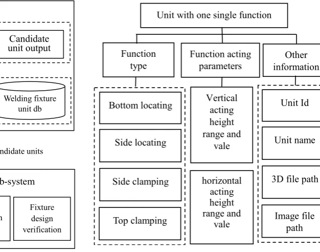
Figure 5 Database construction of CAWFD
Vertical acting height range and
vale
horizontal acting height range and
vale Function
type
Function acting parameters Unit with one single function
Bottom locating
Side locating
Side clamping
Top clamping
Unit Id
Unit name
3D file path
Image file path Other information
Figure 6 Information tree for unit with single function condition 0<Ta<1, which was discussed above. Otherwise,
there is no intersection between the line segment and the arc. If θ1<θa<θ2, the intersection occurs. Otherwise, no
intersection point exists on the line segment and arc. If Δ>0, the line and the arc have two valid intersection points for which
B T
2A
a
± Δ
= − (19) Similarly, each of two points is checked by using the exactly same method discussed whenΔ=0. If 0≤Ta≤1,
the intersection occurs and the intersection position can be identified.
III. DATABASE CONSTRUCTION OF CAWFD
A. Database composition
CAWFD can be divided as two sub-system: interface and framework sub-systems and DB sub-systems [14], which is shown in Fig. 5.
Interface and framework sub-system includes four modules:
1) Setup planning where how many setups are needed to realize the whole assembly welding is determined;
2) Fixture point layout design where fixture points are selected;
3) Fixture configuration design where fixture unit are assembled and mounted on the fixture table;
4) Fixture design verification where the fixture design is checked.
DB sub-system includes three databases: 1) Welding fixture component db, 2)Welding fixture relationship db; 3)Welding fixture unit db.
The interface and framework sub-system will output fixture point type and acting height to DB subsystem. DB subsystem will generate candidate units by searching
component information and relationship among components from component db and relationship db according to point type and acting height requirement satisfaction. Also db sub-system will output these candidate units to the interface and framework sub-system which will be mounted on the welding table.
B. Information tree
Fixture units in database can be divided as two classifications and be represented as corresponding information tree, one is unit with single function and another is unit with multiply function [15].
Unit with one single function (Fig. 6) can be classified as four sub-classifications: bottom locating unit, side locating unit, side clamping unit and top clamping unit. Vertical and horizontal acting height range and vertical/horizontal discrete vale are described in the information tree. Other information such as unit id, unit name, 3D model file path and image file path are also described in the tree.
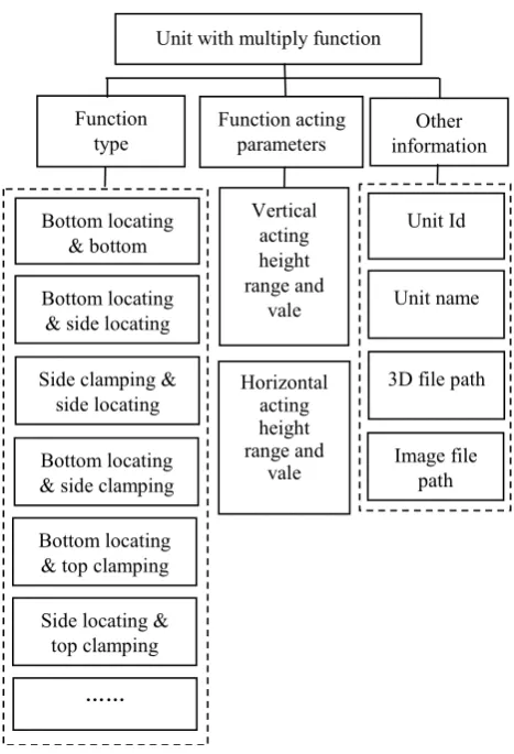
Unit with multiply function (Fig. 7)can be classified as following sub-classifications: bottom locating & bottom locating unit, bottom locating &side locating unit , side locating& side locating unit, bottom locating &side clamping unit , bottom locating& top clamping unit, side locating & top clamping unit and side locating& side clamping unit . Vertical/horizontal acting height range and vertical/horizontal discrete vale are described in the information tree. Other information such as unit id, unit name, 3D model file path and image file path are also described in the tree.
C. Database table design
Based on the information tree, the database tables for database units can be designed as follows Fig. 8 [16-18].
Vertical acting height range and
vale
Horizontal acting height range and
vale Function
type
Function acting parameters Unit with multiply function
Unit Id
Unit name
3D file path
Image file path Other information
Bottom locating & bottom
Bottom locating & side locating
Side clamping & side locating
Bottom locating & side clamping
Bottom locating & top clamping
Side locating & top clamping
……
Figure 7 Information tree for unit with multiply function
Figure 8 Database tables
CREATE TABLE CATDBIIClassification( ID CHAR (10),
Type VARCHAR (50), Note VARCHAR(100), PRIMARY KEY (ID), );
CREATE TABLE CATDBIISubClassification( ID CHAR (10),
ClassificaitonID CHAR (10), Type VARCHAR (50),
Note VARCHAR(100), PRIMARY KEY (ID),
FOREIGN KEY (ClassificaitonID) REFERENCES CATDBIIClassification (ID),
);
CREATE TABLE CATDBIIUnitBasicInfo( ID CHAR (10),
ClassificaitonID CHAR (10), SubClassificaitonID CHAR (10), Name VARCHAR (50),
ModelPath VARCHAR (50), PicturePath VARCHAR (50), PRIMARY KEY (ID),
FOREIGN KEY (ClassificaitonID) REFERENCES CATDBIIClassification (ID),
FOREIGN KEY (SubClassificaitonID) REFERENCES CATDBIISubClassification (ID),
);
CREATE TABLE CATDBIIUnitBasicInfo( ID CHAR (10),
FunctionID CHAR (10), FunctionDirection Integer, FunctionMaxValue Integer, FunctionMinValue Integer, FunctionDiscreteValue Integer, PRIMARY KEY (ID, FunctionID ),
FOREIGN KEY (ID) REFERENCES CATDBIIUnitBasicInfo (ID),
);
IV. MENU AND INTERFACE DEVELOPMENT
A. Construction of integration environment based on UG, Visual C++ and database
1) Integration between UG and Visual C++
The menu and interface are developed based on and seamlessly integrated with UG 5.0, via UG/OPEN/API, using Visual C++ language
2) Integration between Visual C++ and database ODBC (Open Database Connectivity), a standard interface for connecting from visual C++ to relational databases, it allows individual providers to implement and extend the standard with their own ODBC drivers. Here are procedures in Visual C++ coding for connecting to a database.
• Include Header Files
• Open a Connection to a Database
• Choose an ODBC Driver
• Query the Database
• Creating an ODBC Statement Object
• Executing a Query and Returning an ODBCResultSet Object
• Extracting Data from an ODBCResultSet
• Closing the ODBCResultSet and ODBCStatement
• Importance of closing the connection
B. Realization of menu and interface
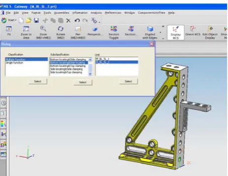
Figure 9 A unit tree management menu
Figure 10 A unit tree management interface
Figure 11 An example of the welding fixture. menu, the interface (Fig. 10) for unit is popped up
[19-23].
The two options single function and multiply function was listed in the ‘classification’ box. Designer can select either one and click ‘Select’ button. The sub-classifications for this classification will appear in the ‘Sub-classification’ box. And designer can also select any of sub-classifications and click ‘Select’ button. Then the units belonging to this sub-classification will be shown in the ‘unit’ box. Designer can select one unit from the unit box. The selected unit will be loaded in the UG and designer can review the unit by rotating and zooming the unit.
C. Application of CAWFD system
In order to meet the demand of rapid reconfiguration of the welding fixture for different work-pieces, appropriate amount of components are designed. The CAWFD system was applied to design a welding fixture. Fig. 11 is an example of the welding fixture [24].
V. CONCLUSION
Welding fixtures have a direct impact upon welding quality, productivity and cost. Currently, most of reported research has been mainly focused on machining fixture,
and the applications of computer aided fixture design (CAFD) technology are still very limited in the welding sector. One key reason is the lack of an effective method that can utilize massive welding-related production data, existing fixture solutions and fixture design experience that is available in a lot of manufacturing companies. Firstly, this paper gives the functions of welding fixture. Secondly, computer-aided welding fixture design workflow and steps are described. And analysis and classification of welding fixture component are completed. Then, the database construction of CAWFD system is provided. Fixture units in database are divided as two classifications and are represented as corresponding information tree. And the database tables to save the unit information are designed. Finally, the unit information retrieval menu and interface based on UG Open/API, Visual C++ and database are realized.
ACKNOWLEDGMENT
We would like to thank Pro. Yiming (Kevin) Rong of Computer-Aided Manufacturing Laboratory, in Worcester Polytechnic Institute. The authors also acknowledge the support of the research from some Corporation and Chongqing University in China.
This research was supported by Chongqing Science and Technology Commission Funded Research Project, fund number CSTC 2008AB3014.
REFERENCES
[1] B. Li, H. Tang, X.P. Yang, and H. Wang, “Quality design of fixture planning for sheet metal assembly”, International Journal of Advanced Manufacturing Technology, vol. 32, pp. 690-697, Apr. 2007.
[2] G.L. Peng,G.D. Wang,W.J. Liua, and H.Q. Yua, “A desktop virtual reality-based interactive modular fixture configuration design system”, Computer-Aided Design, vol. 42, pp. 432-444, May 2010.
[3] Zh.Y. Liu,W.G. Bu, and J.R. Tan, “Motion navigation for arc welding robots based on feature mapping in a simulation environment”, Robotics and Computer-Integrated Manufacturing, vol. 26, pp. 137-144, Feb. 2010. [4] R. H. Alarcón, J.Ríos Chueco, and J.M. Pérez García, “A.
[5] Y. Zheng, and Ch.M. Chew, “A geometric approach to automated fixture layout design”, Computer-Aided Design, vol. 42, pp. 202-212, Mar. 2010.
[6] H. Wang, Y. Rong, and H. Li, “Price Shaun. Computer aided fixture design: Recent research and trends”, Computer-Aided Design, vol. 42, pp. 1085-1094, Dec. 2010.
[7] J.H. Zheng, L.L. He, and X.Z. Ye, “Ontology-Based Knowledge Representation for Computer-Aided Fixture Design”, Journal of Computer Research and Developmen, vol. 47, pp. 1276-1285, Jul. 2010.
[8] Iain Boyle,Y. Rong, and David C. Brown, “A review and analysis of current computer-aided fixture design approaches”, Robotics and Computer-Integrated Manufacturing, vol. 27, pp. 1-12, Jan. 2010.
[9] J. Lin, G.Y. Tan, B.C. Liu, and Y. M. Rong, “Development of Case Database of Fixtures Based on SolidWorks”, Key Engineering Materials, Vol.426-427, 389-393, Apl. 2010. [10]A. Armillotta, G. Moroni, W. Polini, and Q. Semeraro. “A
Unified Approach to Kinematic and Tolerance Analysis of Locating Fixtures”, Journal of Computing and Information Science in Engineering, vol. 10, pp. 11-19, Feb. 2010. [11]H. Song, and Y. Rong, “Locating Completeness Evaluation
and Revision in Fixture Plan”, Computer-integrated manufacturing. , vol. 21, pp. 368-378, Feb. 2005.
[12]L.J. Wang, X.Y. Bai, L.Z. Zhou, and Y.N. Chen, “A hierarchical reliability model of service-based software system,” in Proc. IEEE 33rd International Computer Software and Applications Conference, Seattle WA, pp.199-208, July 2009.
[13]Y. Rong, and Samuel Huang, “Advanced computer-aided fixture design”, Boston (MA): Elsevier Academic Press, 2005.
[14]Y. Kang, Y. Rong, and J.C. Yang, “Computer-aided fixture design verification. Part 1. The framework and modeling” International Journal of Advanced Manufacturing Technology, vol. 21, pp. 27-35, Jul., 2003.
[15]I. Boyle, “CAFixD-A case-based reasoning method for fixture design” Ph.D. dissertation. USA: Worcester Polytechnic Institute, 2006.
[16]I. Boyle, Y. Rong, and D.C. Brown, “CAFixD: A case-based reasoning fixture design method. Framework and indexing mechanisms” Journal of Computing and Information Science in Engineering, Vol.6, pp.40-48, Jan., 2006.
[17]Sh.H. Sun and J.H. Lewis Chen. “Knowledge Representation and Reasoning Methodology based on CBR Algorithm for Modular Fixture Design”. Journal of the Chinese Society of Mechanical Engineers, Vol.28, pp.593-604, June, 2007.
[18]N. Kaya, “Machining fixture locating and clamping position optimization using genetic algorithms”, Computers in Industry, Vol.56, pp. 112-120, Feb., 2006. [19]K. Krishnakumar, and S.N. Melkote, “Machining fixture
layout optimization using the genetic algorithm”, International Journal of Machine Tools and Manufacture, Vol.40, pp.579-598, Apl., 2000.
[20]A.S. Kumar, V. Subramaniam, and T.B. Teck, “Conceptual design of fixtures using machine learning techniques” International Journal of Advanced Manufacturing Technology, Vol.16, pp176-181, Mar., 2000.
[21]F. Mervyn, A.K. Senthil, and A.Y.C. Nee, “Fixture design information support for integrated design and manufacturing”, International Journal of Production Research, Vol.44, pp. 2205-2219, June, 2006.
[22]R. Hunter, J. Rios, J. Perez, and A. Vizan, “A functional approach for the formalization of the fixture design process”, International Journal of Machine Tools and Manufacture, Vol.46, pp. 683-697, May, 2006.
[23]Y.J.G. Liao, S.J. Hu, “Flexible multyibody dynamics based fixture workpiece analysis model for fixturing stability”, International Journal of Machine Tools and Manufacture, Vol.40, pp. 343-362, Feb., 2000.
[24]D.M. Pelinescu, and M.Y. Wang, “Multi-objective optimal fixture layout design”, Robotics and Computer-Integrated Manufacturing, Vol.18, pp.365-372, Mar., 2002.
Yi Zhang obtained his Ph.D. degree in Mechanical Engineering in 2001 and his Master’s degree in Manufacturing Process Automation in 1991 from Chongqing University, China, and his Bachelor’s degree in Mechanical Engineering in 1984 from Harbin Institute of Technology, China. Now he served as Assistant Professor in the Centre for Soft Engineering Research at Chongqing University. He published many research papers in journals. His research interests are Computer-Aided Design and Computer Integrated Manufacturing, Automation and Soft Engineering.