Design and Implementation of 2-Way Wilkinson
Power Divider at Intermediate Frequency 456MHz
using FR4 Substrate
Taufiqqurrachman, Hana Arisesa
Research Center for Electronics and Telecommunication Indonesian Institute of Sciencies (LIPI)
LIPI Campus, Sangkuriang Street, Building 20 - 4th floors, Cisitu Bandung – Indonesia 40135
Phone: +62-22-2504660 Fax: +62-22-2504659
Abstract— This paper presents design and implementation of 2-way Wilkinson power dividers at intermediate frequency 456MHz using FR4 substrate. This design using Wilkinson Power Dividers method where consist of one resistor is connected on the both of output port. Design of the 2-Way Power Dividers presented by simulation result with ADS 2011.10 and have been implemented using FR4 S ubstrate. The measurement results of this design provide an insertion loss, return loss (or VS WR) and isolation with the good result. The 2-way Wilkinson Power Divider with lumped element can be replaced by design on microstrip.
Index Term-- FR4 S ubstrate, Wilkinson Power Dividers
I. INTRODUCTION
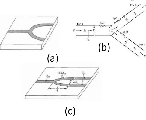
Power dividers are one of passive microwave component and widely used for many communication systems . Power dividers used in dividing power from the input to output ports. 2-way power dividers are often of the equal-division (-3.01dB) type, but unequal power division ratios are also possible [1]. In general, power dividers have three types of dividers like T-Junctions (or the simplest type), resistive and Wilkinson Power Dividers (WPD) as shown in Fig. 1.
Fig. 1. Several of Power Dividers T ype.
(a). T -Junctions (b). Resistive (c). Wilkinson Power Dividers
The WPD have more advantages like lossless (if matched at all port) and high isolation between the outputs port, but have the reflected power is dissipated through isolation resistor if mismatched. The WPD can meet the ideal three-port network conditions (if its matched at all three-ports) and being lossless, reciprocal, matched. So the WPD is the best choice of power dividers [2].
A popular basic configuration of the 2-way WPD is often made in microstrip or stripline form as depicted in Fig . 2a, and the corresponding transmission line circuit is given in Fig. 2b [1].
Fig. 2 T he Wilkinson Power Divider.
(a). An equal-split Wilkinson power divider in microstrip form (b). Equivalent transmission line circuit
In the previous research has been designed and implementation of 2-way WPD use lumped element [3]. Lumped element needs component L and C for build th e 2-way power dividers, but the component C should be use variable/trimmer type for easy to setting the all parameters (insertion loss, return loss (or Voltage Standing Wave Ratio (VSWR)) and isolation) and suitable with the desired specification.
Moreover, the 2-way power dividers with lumped element were only is used for frequency radio (RF) until several GHz because the value of component L and C isn’t available in the local market and the values of the both components too small or big. In order to solve this problem, the 2-way WPD at frequency center 456MHz use microstrip on FR4 substrate has designed and implemented in this paper. The conventional configurations of 2-way WPD with narrowband and broadband have been carried out in the previous paper [4-5] and an unequal split of 2-way WPD was shown in paper [6]. Then the Miniaturized
(a)
(b)
Meander Two-Way Microwave Power Dividers (2WMPD) use mitered bend structures for size reduction have been created in paper [7].
II. DESIGN METHODOLOGY
The 2-way WPD usually employs quarter-wavelength transmission line (λg/4) section at the design center frequency and Wilkinson power consists of two quarter-wavelength line segments at the center frequency (fc)with
characteristic impedance
2*Zo, and a 2*Zo lumped resistorconnected between the output ports [5]. In intermediate frequency (IF) like frequency center at 456MHz, the λg/4 was be length. So that, the λg/4 must be folding and using curved structure proposed in Fig. 3.
(a)
(b)
Fig. 3. T he proposed layout of 2-way WPD with difference length of the quarter-wavelength transmission line (λg/4).
(a). 88.37 mm (type A) (b). 110.29 mm (type B)
Enlarged view of the λg/4 sections that is folded into the meander-coupled line depicted in Fig. 4.
A
B
C
D F
E
H
(a)
A
B
C D
E G
F
H
(b)
Fig. 4. Enlarged view of the λg/4 section for each type.
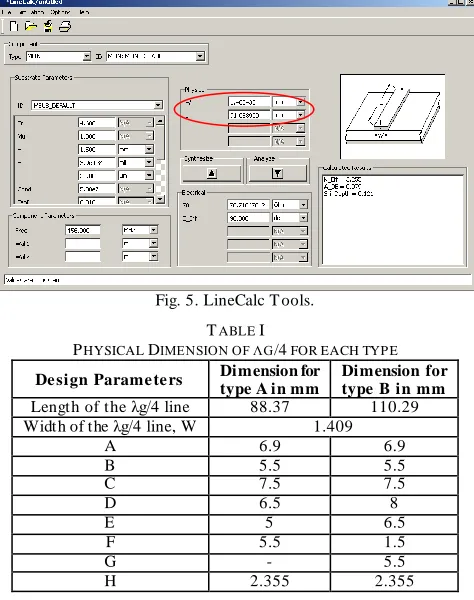
The λg/4 section is folded into a meander-coupled line with assigned parameters. The sum of each parameter is equivalent to the length of λg/4. Curved structure at the both type of 2-way WPD have equal dimension. The width of the microstrip line (W) can find with LineCalc tools on ADS2011.10 software. In LineCalc, the value of impedance characteristic (
2*Zo) was entered to get a physicaldimension of W as shown in Fig. 5. Detail dimension of all parameters of λg/4 for each type on Fig. 4 is shown in Table I.
Fig. 5. LineCalc T ools.
TABLE I
PHYSICAL DIMENSION OF ΛG/4 FOR EACH TYP E
De sign Parame te rs Dimension for
type A in mm
Dimension for type B in mm
Length of the λg/4 line 88.37 110.29 Width of the λg/4 line, W 1.409
A 6.9 6.9
B 5.5 5.5
C 7.5 7.5
D 6.5 8
E 5 6.5
F 5.5 1.5
G - 5.5
H 2.355 2.355
III. SIM ULATION AND MEASUREM ENT RESULT The 2-way WPD with frequency center (fc) 456MHz, Zo =
that can be implemented into a microstrip transmission line as presented in Table II.
TABLE II
IDEAL PARAMETERS OF 2-WAY WPD
Parameters Impedance Value Physical Dime nsion of the Microstrip Line (W) in mm
Zo 50 2.720690
2*Zo 70.7107 1.402430 2*Zo
(resistance) 100 -
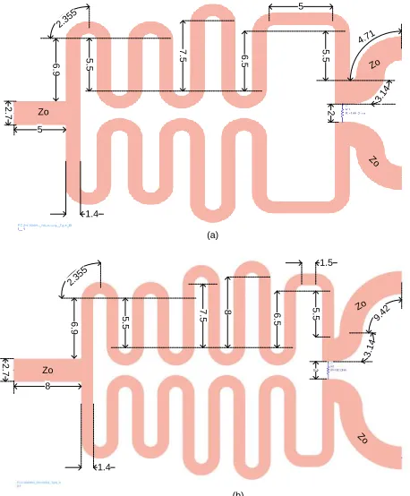
The layout of the 2-way WPD for each type as presented in Fig. 6 while the simulation results for all type are shown in Fig. 6 and 7. The 2-way WPD for each type was further fine-tuned to improve its performance by adding a length of the λg/4 transmission line.
(a) Zo Zo Zo 2 .7 5 5 .5 7 .5 6 .5 5 .5 5 1.4 6 .9 2 2.35 5 3.14 4.71 (b) 8 6 .9 5 .5 8 7 .5 6 .5 5 .5 2 .7 1.4 Zo Zo Zo 2.35 5 2 1.5 3.1 4 9.42
Fig. 6. Layout of 2-way WPD with dimension in mm for each type.
The simulation result from two types of 2-way WPD consists of graph of insertion loss, VSWR and isolation as shown in Figure 7 and 8. For type A, the insertion loss showed that the power divider divides the power equally with transmission loss about 1.96%. Of all the ports have excellent well matched with excellent return loss below -30dB, this is indicating less than 0.1% of the power is reflected back. The isolation between the both output ports has good isolations about -42dB.
Fig. 7. Simulation Result of 2-Way WPD for T ype A. Whereas for type B, the insertion loss showed that the power divider divides the power equally with transmission loss about 1.92%. Of all the ports have excellent well matched with excellent return loss below -35dB, this is indicating less than 0.03% of the power is reflected back. The isolation between the both output ports has good isolations about -47dB. If compared of simulation result the both type, type B have a good the insertion loss, return loss or vswr and isolation ports than type A.
Fig. 8. Simulation Result of 2-way WPD for T ype B The photograph from two types of 2-way WPD on FR4 substrate is shown in Fig. 9.
(a) (b)
isolation measured from Advantest R3860A Network Analyzer are shown in Fig. 10 until Fig. 15.
(a)
(b)
(c)
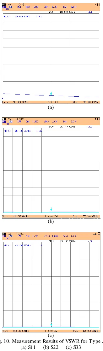
Fig. 10. Measurement Results of VSWR for T ype A. (a) S11 (b) S22 (c) S33
In Fig. 10, VSWR measurement result from type A indicating that port 1 slightly worse than port 2 and port 3 because port 1 have reflection power approximately 1.5% (or VSWR about 1.3) than the port 2 and port 3 have 0.63% (or VSWR about 1.1).
(a)
(b)
Fig. 11. Measurement Results of Insertion Loss for T ype A (a) S12 (b) S13
Furthermore, measurement of insertion loss indicating that power divider divides the power equally with transmission loss about 2% (or approximately -3.2dB) as shown in Figure 11. The output power from the both output s (port 2 and port 3) have a slightly different about 0.021dB at center frequency, it’s called as amplitude unbalanced. The isolation port of type A has a good isolation approximately -33.514dB (as shown in Fig. 12). Its mean that the both of output port (port 2 and port 3) have only transmitt ed signal about 0.05%.
In Fig. 13, VSWR measurement result from type B indicating that port 1 slightly worse than port 2 and port 3 because port 1 have reflection power approximately 0.20% (or VSWR about 1.09) than the port 2 and port 3 have 0.01% (or VSWR about 1.0).
(a)
(b)
(c)
Fig. 13. Measurement Results of VSWR for T ype B Then the insertion loss measurement indicating that power divider divides the power equally with transmissio n loss about 1.94% (or approximately -3.1dB) as shown in Figure
14. The output power from the both outputs (port 2 and port 3) have a slightly different about 0.010dB at center frequency, it’s called as amplitude unbalanced.
(a)
(b)
Fig. 14. Measurement Result of Insertion Loss for T ype B
The isolation port from type A has a good isolation approximately -29.087dB (as shown in Fig. 15). Its mean that the both of output port (port 2 and port 3) have only transmitted signal about 0.13%.
Comparisons between simulated and measured results from two types are presented in Table 3. From Table 3, it can be seen that the VSWR result of type A have a slightly difference about 0.1dB – 0.3dB between simulate and measurement result but type B has only difference about 0.09dB. For the insertion loss, the two types have same differences about 0.1dB. And the isolation port, type B has more differences about 12.68dB than type A has only about 9.34dB.
From the all parameters measurement on two types 2-way WPD have been designed and measured, type B has a good value of VSWR and insertion loss than type A. But the value of isolation port type A has a slightly good than type A. It caused by the configuration length of the quarter-wavelength is different in the two types.
TABLE III
SUMMARY RESULT OF THE BOTH TYP E BETWEEN SIMULATION AND
MEASUREMENT
Parame te rs Simulation Me asure me nt
Type A Type B Type A Type B
VSW R :
S11 1.000 1.006 1.324 1.098 S22 1.002 1.003 1.163 1.028 S33 1.002 1.003 1.148 1.008
Inse rtion Loss : (in dB)
S12 -3.137 -3.081 -3.261 -3.154 S13 -3.137 -3.081 -3.242 -3.144
Isolation (S23),
in dB -42.904 -41.767 -33.514 -29.087
IV. CONCLUSION
The two types of 2-way Wilkinson Power Divider (WPD) has been successfully designed, simulated and fabricated. The proposed configuration with folded of the quarter-wavelength segment into meander-line coupled has been achieved to get physical dimension of the 2-way WPD smaller than the conventional structure or the 2-way WPD using lumped element. And better performance than conventional design or by using a lumped element . The configuration of type B have a good insertion loss and return loss (or vswr) than type A with adding length of the quarter-wavelength segment. But the configuration of type B has a slightly worse of isolation port than type A. For further project, the 2-way WPD can be designed for smaller size and other configuration meander coupled -line of the λg/4 transmission line.
ACKNOWLEDGEM ENT
This project was supported by RADAR project on Research Center for Electronics and Telecommunication - Indonesian Institute of Sciencies (PPET-LIPI).
REFERENCES
[1] David M. Pozar, “Microwave Engineering”, 3rd Ed., John Wiley & Sons Inc., New York, 2005.
[2] Daniel D. Harty, “Novel Design of A Wideband Ribcage-Dipole Array and Its Feeding Network”, T hesis of Master degree of Science in Electrical and Computer Engineering of Worcester Polytechnic Institute, Dec 17, 2010.
[3] T aufiqqurrachman, Arisesa Hana, “Design and Realization of a Low Cost T wo-Way Wilkinson Power Divider at Intermediate Frequency for a RADAR System”, Proceeding on ICRAMET , April 2012. [4] Bajee Bobba, Dominic Labanowski, T om Zajdel and Cameron Zeeb, “Design and Analysis of an Equal Split Wilkinson Power Divider”, Proposal Design on Jan 11, 2010.
[5] Huang Guangpu, Qing Songlin, Fu Jeffrey, Kwang Lee Ching, “Design of Narrowband and Broadband Wilkinson Power Divider”, Design and Innovation Project – School of Electrical & Electronic Engineering, Nanyang T echnological University.