ISSN (e): 2250-3021, ISSN (p): 2278-8719 Vol. 08, Issue 5 (May. 2018), ||VI|| PP 07-14
Simulation of Hybrid D-STATCOM for Commercial Load in
Three Phase Four Wire Distribution System
Abhay Wagh
1, Karuna Nikum
2, Rakesh Saxena
3, Bharat Mishra
4 1(Electronics, DTE, Govt. of Maharashtra, India)2(Electrical, Atharva College of Engg,/Mumbai University, Research Scholar of MGCGV, India) 3(Electrical, SGSITS,/RGPV,India)
4(Physical Science, MGCGV University, Satna, India)
Corresponding Author: Abhay Wagh
Abstract : The growth of electricity market has seen a change in the sense consumers perceive electricity. The electricity consumption can be roughly divided between three larger sectors — industry, household and commercial sector. This paper attempts to monitored and analyzed power quality (PQ) issues in commercial sector with a real case study for commercial load taken as educational building in Indore, India. The commercial or educational buildings major loads are computers, energy efficient lightings and official loads etc. This single phase loads within a building leads to a large amount of harmonics, mainly in neutral. A Hybrid distributed static compensator (D-STATCOM) is proposed to mitigate these harmonics. A hybrid D-STATCOM is combination of 3-phase D-STATCOM with small rating of 1-phase active power filter(APF) with T-connected transformer. The APF specially connected for third order harmonics in neutral. The proposed combination reduces harmonics, cost as well as size of the filters. The model of hybrid D-STATCOM is simulated in MATLAB with similar harmonics conditions. The results of simulation are satisfactory to mitigate most of the harmonics to meet the recommended standard of IEEE 519-2014.
Keywords –Commercial load, harmonics, Hybrid D-STATCOM,IEEE 519-2014, APF, Power quality monitoring, PQ, Power quality issue.
--- --- Date of Submission: 23-04-2018 Date of acceptance: 11-05-2018 --- ---
I. INTRODUCTION
Simulation of Hybrid D-Statcomfor Commercial Load in Three- Phase Four-Wire Distribution System
Voltage THD: Total Harmonic Distortion of the voltage waveform. The ratio of the root-sum-square value of the harmonic content of the voltage to the root-mean-square value of the fundamental voltage.
𝑇𝐻𝐷𝑣 = √(V2
2+ V
32+ V42… .
V1 (1)
Current THD: Total Harmonic Distortion of the current waveform. The ratio of the root-sum-square value of the harmonic content of the current to the root-mean-square value of the fundamental current.
𝑇𝐻𝐷𝑖 = √(I2
2+ I 3 2+ I
4 2… .
I1
(2)
Current TDD: Total Demand Distortion of the current waveform. The ratio of the root-sum-square value of the harmonic current to the maximum demand load current.
𝑇𝐷𝐷𝑖 =√(I2
2+ I 3 2+ I
4 2… .
IL
(3)
As per the guideline of IEEE 519-2014, the total harmonic distortion of voltage (THDv) should be below
5%. For current distortions TDD must be less than 8% for the ratio of Isc/IL is in between 20 to 50. In this case
the ratio for this building is in between 20 to 50.
II. SYSTEMDESCRIPTION
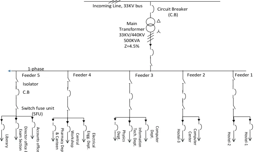
The system is supplied with 33 KV incoming line via step down transformer of 3-phase, 50 Hz, 33 KV/440 V, 500 KVA with source impedance (Zs) of 4.5%. This commercial educational building having five different feeders to supply different types of loads as shown in figure 1.
Incoming Line, 33KV bus
Circuit Breaker (C.B) Main Transformer 33KV/440KV 500KVA Z=4.5% C.B Isolator
Feeder 4 Feeder 3 Feeder 2 Feeder 1
Feeder 5 H os te l-2 Ho ste l-1 C om pu te r C en ter Ho stel -3 C om pu ter D ep t. In fo rm at io n Te ch . D ep t. Ph ys ic s D ep t. Ele ct ric al En gg . D ep t. C en tra l W o rk sh o p Ph ar m ac y D ep t. & C an teen A cc ou nt s o ffic e D ire cto r o ffi ce & Ex am S ec tio n Lib er ar y 1-phase
Switch fuse unit (SFU)
Figure. 1 Single line diagram of load feeders
III. POWERQUALITYMONITORINGOFALLFEEDERS
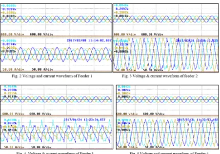
Detailed harmonic analysis has been done for identifying the source of high harmonics in all five feeders as shown in figure 2,3,4,5 & 6. In commercial building 3rd harmonics is a big problem. As per the readings as
Table 1.Detail of Total harmonic distortions (THD) in all five feeders
Feeder 1 Feeder 2 Feeder 3 Feeder 4 Feeder 5
S.N THDi THDv THDi THDv THDi THDv THDi THDv THDi THDv
CH1 8.18 2.07 7.33 1.34 11.89 1.44 4.80 1.93 17.82 2.90
CH2 6.25 2.07 6.91 1.44 15.71 1.42 6.11 1.71 19.67 2.50
Simulation of Hybrid D-Statcomfor Commercial Load in Three- Phase Four-Wire Distribution System
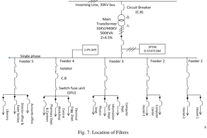
The power rating of the compensated system and its speed of response play a major role in deciding the control technique to implement the required filter. The cost of any particular system is proportional to the required speed of the response. As per the monitoring results, the feeder 3 and 5 are affected by the harmonics. In this paper, a hybrid D-STATCOM has been proposed, which is consist of mainly 3-phase non isolated DSTATCOM connected at 3-phase side of main transformer secondary, and 1-phase APF with T-connected transformer connected specially for 3rd harmonics in neutral of feeder 3 and 5 as shown in table 1.
Incoming Line, 33KV bus
Circuit Breaker (C.B) Main Transformer 33KV/440KV 500KVA Z=4.5% C.B Isolator
Feeder 4 Feeder 3 Feeder 2 Feeder 2
Feeder 5 H os te l-2 Ho st el-1 C om pu te r C en ter Ho st el -3 C om pu ter D ep t. In fo rm at io n Te ch . D ep t. Ph ys ic s D ep t. Ele ct ric al En gg . D ep t. C en tr al W o rk sh o p Ph ar m ac y D ep t. & C an teen A cc ou nt s o ffi ce D ire ct o r o ffi ce & Ex am S ec tio n Lib er ar y Single phase
Switch fuse unit (SFU)
1-Ph APF D-STATCOM3P3W
s Fig. 7. Location of Filters
4.1D-STATCOM
A static synchronous compensator (STATCOM) with or without a coupling transformer, an inverter, and energy storage devices used in distribution system is called D-STATCOM. D-STATCOM include voltage source converter (VSC), DC bus capacitor and ripple filter. The D-STATCOM. The main function of D-STATCOM is to supply reactive power to regulate the voltage at point of common coupling. Active power can also be supplied if storage is connected at DC side.
4.2 APF
Active power filters (APF) is an instantaneous voltage source converter. APF mitigates the harmonics generating anti harmonics into the system and thereby cancelling the harmonics present into the system.
4.2.1 T-Type Transformer
T type transformer is small in floor space, low in height and with lower in weight. It uses two single phase transformers which make core economical and easy to assemble it can be regarded as open circuit for the positive and negative sequence currents hence the current flowing through the transformer is only zero sequence current.
V. SIMULATIONOFHYBRIDD-STATCOM
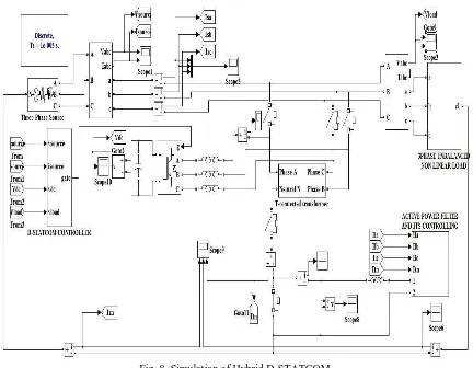
Fig. 8. Simulation of Hybrid D-STATCOM
5.1 Three-Phase Three-Wire (3P3W) D-STATCOM
A three-leg, two level pulse width modulated (PWM) voltage source inverter (VSI) is used as the D-STATCOM in this configuration. The VSI is realized by using insulated-gate bipolar transistor (IGBT) switches and operated through a three-leg, PWM switching scheme.
5.1.1 Control of 3P3W D-STATCOM
The PWM signals are generated by a suitable control scheme for which reference and sensed D-STATCOM currents are the input signals. Several control schemes have been reported in the literature for extraction of load harmonic and reactive currents and they are based on instantaneous reactive power (IRP) theory, power balance theory, synchronous reference frame theory, symmetrical components based theory and etc. In this paper synchronous reference frame (SRF) theory is used to generate control signals.
5.1.2 SRF Theory-Based Control Algorithm of D-STATCOM
A block diagram of the control algorithm is shown in Figure. 9. The load currents (iLa, iLb, iLc),
point of common coupling (PCC) voltages (vsa, vsb, vsc), and DC bus voltage (VDC) of the DSTATCOM are
sensed as feedback signals. The load currents in the three phases are converted into the dq0 frame using the Park’s transformation. A three-phase PLL (phase locked loop) is used to synchronize these signals with the PCC voltages. These d–q current components are then passed through a low pass filter ( LPF) to extract the DC components of iLd and iLq. The d-axis and q-axis currents consist of fundamental and harmonic
Simulation of Hybrid D-Statcomfor Commercial Load in Three- Phase Four-Wire Distribution System
abc
d-q-0
d-q-0
abc
3-phase PLL Amplitude PI Controller Current-Controlled PWM Controller LPF LPF LPF PI Controlleri
los s V*DC VDCi
Lai
Lbi
Lci
Ldi
Lqi
dDCi
qDCi*
di*
qi*
sai*
sbi*
sci
sai
sbi
sc Vsa Vsb Vsc Vsp V*s1i
qr Gate pulses for three-leg VSC CosӨ, SinӨFig9. Block diagram of SRF theory-based control algorithm of D-STATCOM’
5.2 APF with T-Connected transformer
The rating of the APF is very small due to the low voltage drop across the T-connected transformer neutral and the utility neutral (VTn). This voltage is primarily determined by the sum of the
voltage drops across the leakage impedance of the T-connected transformer and filter inductor due to the compensating current of the source neutral. However, under sustained unbalanced/distorted utility voltage conditions or fault conditions, VTn can be very high. This makes it necessary to protect the single-phase
APF and T-connected transformer by means of a protective device. For better compensation under nominal unbalanced and/or distorted conditions, the dc side voltage of the single-phase inverter is kept at three times the peak voltage drop between the T-connected and utility neutrals with ideal utility voltage.
5.2.1 Operation and control of single-phase APF
When T-connected transformer only acts as compensator (Switch closed) then the transformer provides a low impedance path for the zero-sequence currents to flow between the load and the T- connected transformer. However, the effectiveness of the compensation is strongly dependent upon the location of the compensator and impedances of the T-connected transformer, and the system. When switch (S) is open, the single-phase APF comes into the operation and produces the desired current for compensating source neutral current and injects the same through the neutral of the T-connected transformer. This current splits equally and flows through each of the T-connected windings of the transformer such that the APF circulates the neutral current to the load via the T-connected transformer. Therefore, the effectiveness does not depend on the zero-sequence impedance of the T-connected transformer and its location and hence a special design for a T-connected transformer for low zero-sequence impedance is not necessitate.
5.2.2. Operation of under unbalance/distorted utility voltages
The performance of the only T-connected transformer (S closed) also depends upon the utility voltage conditions. Under unbalanced and/or distorted source voltage conditions, a zero- sequence voltage may exist which provides a low impedance path for the zero-sequence current to flow between the utility and the T-connected transformer. Therefore, the source neutral current becomes larger than the load neutral current and which will have an adverse effect on the performance and may result in the burn down of the transformer or the neutral conductor. But, with single-phase APF, the compensating source neutral current forcibly injects through the neutral of the T-connected transformer and hence its effectiveness of compensation of neutral current does not depend on utility voltage conditions.
VI.RESULTS
6.2 Results with only D-STATCOM
As the result shows that, alone D-STATCOM reduced THD till 8.7% from 20%. The 3rd harmonics
reduces from 13% to 9%, 5th harmonics reduces from 10% to 3%, 7th harmonics reduces from 8% to 1%and all
higher harmonics are reduced below 0.5%.
6.3 Results with D-STATCOM and APF
Simulation of Hybrid D-Statcomfor Commercial Load in Three- Phase Four-Wire Distribution System
VII. CONCLUSION
The proposed methodology uses the combination of 3-phase D-STATCOM in main line of transformer secondary and single phase APF with T connected transformer in feeder. This combination make the size of D-STATCOM is of small and having low KVA rating. This hybrid D-STATCOM is economical by cost, small in size and simultaneous compensate reactive power, load current harmonics and source neutral current. The APF with T-connected transformer has an advantage of using standard two single-phase transformers and consequently, the cores are economical to build and occupy low space. The performance of the proposed D-STATCOM has been investigated through simulation in MATLAB. It is observed that the proposed scheme completely compensated the source current harmonics, reactive power and neutral current. The proposed D-STATCOM has better performance under unbalance/ distorted utility voltage conditions and also it does not need a special design for T-connected transformer for low zero-sequence impedance. The single phase APF are generally available in low power ratings and suitable for medical, small shops or educational buildings with computers and lighting loads, where the current harmonics are dominated. To reduce the cost, several lower power filters can be connected at affected feeder rather than using one large filter on incoming supply or at PCC. Therefore, the proposed DSTATCOM topology will have reduced weight, cost, rating, size with improved efficiency and current compensation capability compared with the traditional topology. The effectiveness of the proposed DSTATCOM topology over traditional topologies is validated through simulation.
REFERENCES
[1] Pooya Bagheri, Wilsun Xu, Tianyu Ding, A Distributed Filtering Scheme to Mitigate Harmonics in Residential Distribution Systems, IEEE transactions on power delivery, 31(2), 2016.
[2] V. C. Sekhar, K. Kant and B. Singh, DSTATCOM supported induction generator for improving power quality," IET Renewable Power Generation, 10(4), 2016, 495-503.
[3] Y. Deng, X. Tong and H. Jia, Effects of voltage harmonics on Distribution Transformer Loss, IEEE Transactions on Industrial Informatics, 11(1), 2015, 141-154.
[4] K. D. McBee and M. G. Simoes, Evaluating the long-term impact of a continuously increasing harmonic demand on feeder-level voltage distortion, IEEE Trans. Ind. Appl.,50(3) 2014, 2142–2149. [5] Xiao-Xi Cui, Hong-Ming Mei, and Jian-Zheng Liu, Design and Performance of an Adaptive
[6] K. D. McBee and M. G. Simoes, An Improved Hybrid DSTATCOM Topology to Compensate Reactive and Nonlinear Loads, IEEE Trans. Ind. Appl., vol. 50(3), 2014, 2142–2149.
[7] Chandan Kumar and Mahesh K. Mishra, An Improved Hybrid DSTATCOM Topology to Compensate Reactive and Nonlinear Loads, IEEE Transactions On Industrial Electronics, 61(12), 2014. [8] P. Bagheri and W. Xu, A technique to mitigate zero-sequence harmonics in power distribution systems,
IEEE Trans. Power Del., 29(1), 2014, 215–223.
[9] IEEE Recommended Practices and Requirements for Harmonic Control in Electric Power systems, IEEE Standard 519-1992.