Direct Torque Control System for Coal Mine
Equipment Based on Improved Genetic
Algorithms
Zhanshe YangElectrical and control engineering institute Xi'an university of science and technology xian city Shanxi Province China
Email: [email protected]
Xianmin Ma
Electrical and control engineering institute Xi'an university of science and technology xian city Shanxi Province China
Email: [email protected]
Abstract—The belt conveyor is the main transport equipments in coal field, and its controllable dirve system directly impacts on the running safety reliability and cost in coal production. Starting speed is unsmoothed in the traditional electrical drive system, which causes the belt off tracking or split and even safty accident. Therefore it is theory and practical significant to introduce a novel direct torque control (DTC) system of AC machine to the belt conveyor for solving the problem in coal mine. In allusion to the optimization of PID parameters in the speed regulators of the belt conveyor, the paper presents the improved genetic algorithm based on genetic algorithms and tabu search for the design of variable parameters of PID controller, and its ability of stronger climbing and faster finding the global optimum results are verified through the De Jong function. Compared with the traditional means, the rise time of the suggested system is faster, overshoot and regulating time is shorter, anti-disturbance is stronger, robust is better. So the optimization performance of control system is improved greatly.
Index Terms—Belt Conveyor;Direct Torque Control (DTC);Genetic Algorithms; Tabu Search
I. INTRODUCTION
The belt conveyor is a big Inertia load and a main transport vehicle in the coal mine safety production[1]. Because in the early the belt conveyer power was small and the transport distance was short, and the speed was low[2]. Its application was certainly limited. Along with electric power electronic technology and variable frequency modulation technology development, the belt conveyer technology had has been developed greatly, and it gradually becomes the most reliable and the most economical equipment in transportation bulk[3]. But there are still have some problems because the adhesive tape belongs to the flexible belt body. It requests the low and steady speed to start and it can not have the impact. Otherwise it is easy to break[4]. Moreover, it is easy to happen the phenomenon which the material rolls from the
adhesive tape, so the belt conveyer's start acceleration generally must be controlled within
0
.
3
m
/
s
2.Drive motor power of the belt conveyor is usually bigger , there are big impact current when the motor is started. This will spark the voltage Sharply descend of electrical power system , it May spark failure to start, it can cause been burn to motor. Even it will effect the normal run - time of other electricity equipments.
The improved heredity taboo algorithm is proposed in the direct torque control's foundation in this paper, which solves speed regulator PID parameter optimization in the mineral belt conveyer[5]. Because of intersecting calculate the likeness of the chromosome and the dimension of the variation probability in inherit algorithm, "Precocious" phenomemon and climbing a mountain of algorithm capability that easily builds to run in the family algorithm are weak, it make its incapability to search overall situation's superior solution, But this second inspire type huning technique as the variation that inherits algorithm to calculate son is leaded into taboo to search, This problem Was useful to work out. At the same time to PID controller , punishment function is adopted in order to avoid super adjust. This algorithm has “climb the mountain” and seeks for the globally optimal solution quickly ability. The control system optimization performance is greatly enhanced by using this algorithm[6].
ⅡSIMULINK FIGURE OF DIRECT TORQUE DIRECT TORQUE CONTROL SYSTEM
A: Asynchronous motor mathematical model
In order to mathematical model of induction motor make more general in two-phase coordinate , Here we consider mathematical model of asynchronous motor in arbitrary rotate
d
,q
reference frame,d
,q
referenceWith
ω
1, Now for the stator rotation transformationmatrix for
⎥
⎦
⎤
⎢
⎣
⎡
−
=
1 1 1 1 2 /2
sin
cos
sin
cos
θ
θ
θ
θ
s sC
,Rotor transform matrix
for
⎥
⎦
⎤
⎢
⎣
⎡
−
−
−
−
−
=
)
cos(
)
sin(
)
sin(
)
cos(
1 1 1 1 2 /2r r
θ
θ
θ
θ
θ
θ
θ
θ
C
. Asynchronous motors voltage equation, flux equations and torque equation are obtained in any coordinate, These are ⎥ ⎥ ⎥ ⎥ ⎦ ⎤ ⎢ ⎢ ⎢ ⎢ ⎣ ⎡ − − − − + ⎥ ⎥ ⎥ ⎥ ⎥ ⎦ ⎤ ⎢ ⎢ ⎢ ⎢ ⎢ ⎣ ⎡ + ⎥ ⎥ ⎥ ⎥ ⎥ ⎦ ⎤ ⎢ ⎢ ⎢ ⎢ ⎢ ⎣ ⎡ ⎥ ⎥ ⎥ ⎥ ⎦ ⎤ ⎢ ⎢ ⎢ ⎢ ⎣ ⎡ = ⎥ ⎥ ⎥ ⎥ ⎥ ⎦ ⎤ ⎢ ⎢ ⎢ ⎢ ⎢ ⎣ ⎡ rd r rq r sd sq q rd sq sd rq rd sq sd r r s s rq rd sq sd p i i i i R R R R u u u u
ψ
ω
ω
ψ
ω
ω
ψ
ω
ψ
ω
ψ
ψ
ψ
ψ
) ( ) ( 0 0 0 0 0 0 0 0 0 0 0 0 1 1 1 1⎥
⎥
⎥
⎥
⎥
⎦
⎤
⎢
⎢
⎢
⎢
⎢
⎣
⎡
⎥
⎥
⎥
⎥
⎦
⎤
⎢
⎢
⎢
⎢
⎣
⎡
=
⎥
⎥
⎥
⎥
⎥
⎦
⎤
⎢
⎢
⎢
⎢
⎢
⎣
⎡
rq rd sq sq r m r m m s m s rq rd sq sdi
i
i
i
L
L
L
L
L
L
L
L
0
0
0
0
0
0
0
0
ψ
ψ
ψ
ψ
)
(
sq rd sd rq mp
e
n
L
i
i
i
i
T
=
−
B: Simulink figure of direct torque direct torque control system
Direct torque control is that mathematical analysis method of space vector is used in asynchronous motor stator coordinates and electromagnetic torque motor is directly calculated and controlled, Direct torque control system chart shown in figure 1.
Figure 1. Direct torque control system diagram C: Basic composition of Direct torque control system
The essence of direct torque control is that electromagnetic torque motor are direct calculated and controlled , Using space vector mathematical analysis method In asynchronous motor stator coordinates. system structure of direct torque control is shown in following figure3.
Its working principle is which A voltage type inverter in a working condition, stator flux along the path of the state of stator voltage vector corresponding direction, speed is proportional to the voltage vector amplitude 4/3E
(E: inverter dc input voltage half). Using magnetic chain Bang Bang - switching voltage vector control the working condition, can make the magnetic chain path according to approximate circle (or hexagon) movement. If you want to change the stator flux vector rotation speed, can introduce zero voltage vector. In zero state, the voltage vector is equal to zero, stop rotating magnetic chain motionless. Using torque of Bang Bang - working condition and control used alternately, zero magnetic chain, which changes the considerable stop-and-go magnetic chain the size of the average rotational speed, and changed the magnetic flux Angle of size, achieve control motor torque purpose. Torque, magnetic chain closed-loop control needed by the feedback control quantity motor stator side torque, flux estimation model calculation examples.
D: Inverter voltage state
Inverter is one of the most important components in the Ac speed regulation system, Motor speed and magnetic chain is adjusted by control inverter switch sequence, Inverter have two kinds that is voltage type and current type .The voltage type inverter is used for asynchronous motor direct torque control system. as shown in figure 2 shown.
2
du
2
du
s
aa
s
b
s
s
cb
s
s
cFigure 2. Three-phase voltage type inverter
Inverter have three groups, six switch (
S
a,
S
a,
S
b,
S
b,
S
c,
S
c) composition, in the table 1,a
u
,u
b andu
c are output phase voltage. In order toanalyze convenience , the dc power supply voltage is divided two parts, , two parts voltage is
2
/
du
respectively. Among them, the same bridge underhis arm, two switch components are complementary action, that at the same time, they are always disconnect and closed, for example when
S
a=
1
, that is inverter ofA bridge arm, Top switch is closed and below switch is disconnect; when
S
a=
0
, by contrast, below switch isclosed, top switch is disconnect . If required, there is a phase load of a, b and c extremely connect with power "+", the phase switch state for "1" state, conversely, and connect with power "-" the phase switch state "0" state. Then inverter consists of eight kinds of switch combination, as shown in table 1. This combination of eight kinds of switch state into two kinds: one kind is 6 kinds of so-called working status, their characteristic is three-phase load are not receiving the same potential up; Another type of switch state is zero, they switch state is characteristic of three-phase load were received the same potential up.
INVERTER EIGHT KINDS OF SWITCH COMBINATION STATE
state 0 1 2 3 4 5 6 7
switch combination
a
S
0 1 1 0 0 0 1 1b
S
0 0 1 1 1 0 0 1c
S
0 0 0 0 1 1 1 1Inverter six working state get six different direction voltage space vector, they appear periodically order between adjacent two vector are 60 and voltage space vector amplitude is changeless, are equal to 34
E
(
E
=
12u
d). So six voltage vector vertex may constitutea hexagonal six vertex, can be used as a three-phase inverter with various state output voltage. Direct torque is according to the flux and the torque requirements, from 8 voltage space vector a selection of optimal control vector, make the motor running in a particular state.
E: Asynchronous motor magnetic chain model
In direct torque control system, according to different combinations, we can get different flux estimation method, model of the
u
−
i
andi
−
n
are adopted. The stator flux linkage of asynchronous motor stator can be used to determine by the stator voltage and current.∫
−
=
Ψ
sα(
u
saR
si
sa)
dt
∫
−
=
Ψ
sβ(
u
sβR
si
sβ)
dt
s
u
s
i
s
i
s
u
s
R
s
s
s R
Figure 3.Stator flux voltage model
n
i− Model and say current flux model, with stator current calculation magnetic chain, its computation formula is as type, structure shown Figure 4.
⎪
⎪
⎪
⎪
⎪
⎩
⎪⎪
⎪
⎪
⎪
⎨
⎧
+
=
+
=
−
+
=
−
−
=
β β
β
α α
α
β α
β β
α β
α α
σ
ψ
ψ
σ
ψ
ψ
ψ
τ
ωψ
τ
ψ
ψ
τ
ωψ
τ
ψ
s s r
r m s
s s r
r m s
r r r r
r m r
r r r r
r m r
i
L
L
L
i
L
L
L
i
L
i
L
1
1
where
r r r
R
L
=
τ
L
(
L
rL
sL
m)
/
L
m2
−
=
σ
r
ψK
s
ψK
s
iK
Figure 4. current model of the stator flux linkage
The current model in low-speed than voltage model by motor parameters accurately, but the influence of rotor time constant, especially in high speed, as voltage model is accurate.
F: Simulink figure of direct torque direct torque control system
Figure 5. System simulation diagram
III. IMPROVEDGENETICALGORITHMFORPID
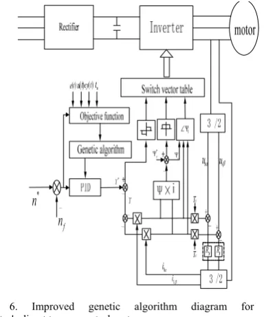
Figure 6. Improved genetic algorithm diagram for PID modulator's direct torque control system
Improved genetic algorithm PID is used in the speed regulator[7]. According to the demand which the belt conveyer is requested synchronous to electrical motor and response curve, the rising time will forecast electrical machinery's rotational speed target, and controller's output and the speed error are added the objective function of the PID speed regulator, and the improved objective function is to gain the satisfactory transient process dynamic characteristic, thus system's control performance is improved.
IV. INSTALLATION STEPS OF IMPROVED HEREDITYTABOOALGORITHMTOOPTIMIZE
NONLINEARPIDSPEED REGULATOR
PARAMETERS
The installation steps which speed regulator parameter based on heredity taboo's nonlinear PID is as follows:
A. Codes
Determinating that the number of optimization variables integer is 3, and using the series binary system mapping coding method, each parameter is expressed with 10 non-mark binary code, and the individual length =3 was *10 position. Supposes the parameter value scope is from for pmax.j to
p
min.j, then the actual parametervalue's relations between the parameter string expression
values is: 1 2 ) ( 1 2 ) ( 2 . min . max . min 1 . min . max . min − − + = − − + = − R p p p R p p p
pj j ji j j j j
. In the formula i is the parameter number. In this paper regulator's parameter number is 3, the value scope of
p
k
is [0, 20], and the value scope of
k
iandk
d are [0, 1].B. Adaptive Function
To obtain the satisfactory dynamic characteristics, the erroneous absolute value time integral performance is used as the smallest item of the sign function. In order to
prevent the control output being oversize, a square item is added in the objective function of the control input. Selecting the equation below to take the parameter selection the most superior target:
∫
∞⋅ + +
= 0 w1e(t) w2u2(t))dt w3 tu J
where
e
(
t
)
is the system error, andu
(
t
)
is outputs of the controller, andt
u is the rising time,and
w
1,w
2,w
3is the weight.In order to avoid the over-shoot, the penalty function has been used, that means it has the shoot and over-shoot most superior target's one item, this time the most superior target is:
if
( ) 0
e t <
∫
∞ + + + ⋅= 0 (w1e(t) w2u2(t) w4|ey(t)|)dt w3 tu
J
where
w
4is a weight , andw
4>>
w
1,)
1
(
)
(
)
(
t
=
e
t
−
e
t
−
ey
.Takingw
1=
0
.
999
,011
.
0
2
=
w
,w
3=
1
.
96
,w
4=148.C. Population Size
When using genetic algorithm, what needed to solve firstly is to determine the population size. If the size can not guarantee the population individual variety and the optimization space is small, the convergence comes ahead of the time. Otherwise, if it is too big, then the computation burden is increased and the genetic algorithm efficiency is decreased[8]. The choice of the large number of initial population may produce more solutions simultaneously in general, and it is easy to find the globally optimal solution. But its shortcoming is the time-increasing for the each iteration[9]. Generally the population size takes the twice of the code length, namely n=2×
l
=60.D. Overlapping Operator
The choice of overlapping operator
p
c can affect thebehavior and performance of the genetic algorithm.
p
cchanges automatically along with the sufficiency[10].
p
cis calculated according to the equation below.
⎪⎩
⎪
⎨
⎧
−
−
′
−
−
=
1 max 2 1 1)
)(
(
c avg avg c c c cp
f
f
f
f
p
p
p
p
avg avgf
f
f
f
<
′
≥
′
where the value scope is Pc1=0.9, Pc2=0.6;
f
maxisthe biggest sufficiency in community;
f
avg is theaverage sufficiency in each generation of community;
f
′
is the bigger sufficiency of the 2 overlapping
⎪⎩
⎪
⎨
⎧
−
−
−
−
=
1 max
max 2 1
1
(
)(
)
m avg m m m m
p
f
f
f
f
p
p
p
p
avg
avg
f
f
f
f
<
′
≥
where the value scope is
p
m1=
0
.
1
,p
m2=
0
.
001
.Figure 7. Improved Genetic Algorithm Flow Chart
V. MATLABSIMULATIONRESULT
Giving an improved genetic algorithm, the population size is 60 ; the chromosome length is 30; the number
of evolution generation is 80; the auto-adapted overlapping probability is respectively:
p
c1 =0.9,2
c
p
=0.6; the scope of parameterk
p is [0, 20], the valuescopes of
k
iandk
d’s are [0, 1]. After 100 generation ofevolutions, the optimized parameter are obtained
p
k
=19.5156,
k
i=0.2463,k
d=0.0.Figure 8. Simulation Wave of Speed Response
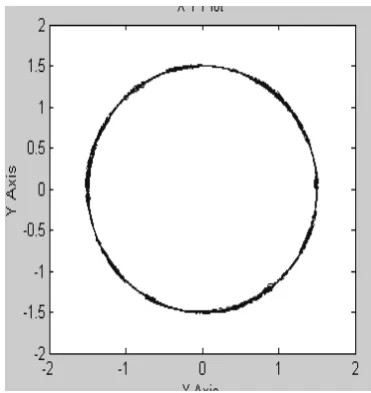
Figure 9. DTC movement Flux Linkage Circle Diagram
Figure10. GATS DTC Movement Flux Linkage Circle Diagram
movement, then flux linkage circle diagram of the direct torque control is more closer circle than the tradition flux linkage circle diagram.
Figure 11. Two kinds of kp conditioning that inherit algorithm
Figure 12. Two kinds of ki conditioning that inherit algorithm
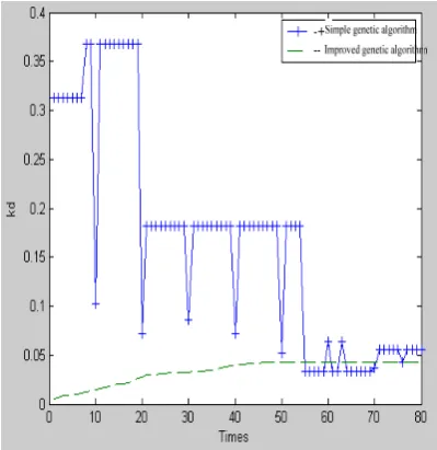
Figure 13.Two kinds of kd conditioning that inherit algorithm
From the figure 8, we can draw a conclusion that rise time of curve 1 is the quickest, but the super - adjusts quantity of curve 1 is maximum, there is about 30%.Rise
time of curve 2 and 3 is not change, but super - adjusts quantity of curve 2 is high than curve 3. the super - adjusts quantity of curve 3 is about 5%.
From the figure 11, figure 12and figure 13, we can draw a conclusion that Convergence velocity is quicker of Improved genetic algorithm than simple genetic algorithm , And optimal values is earlier looked. optimal value have already looked for at 50 in improved genetic algorithm.
TABLE2
VELOCITY COMPARATION OF TWO KINDS OF HEREDITY ALGORITHMS
From the table 2, We can discove that Convergence velocity is quicker of Improved genetic algorithm than simple heredity algorithm.
Figure 15. Revolving speed waveform of with 5 s in start
Figure 16 . The torque watches waveform with 0.5s in start
t/s
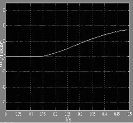
Figure 17. Revolving speed watched waveform with 0.5s in start
Figure 18. current waveform with 0.5 s in start
From the figure 14 and figure 15, we can draw a conclusion that the torque pulsation is smaller with 6 s in start, and the revolving speed waveform is steady to up. From the figure 18, the current impact takes place at 40ms, Its maximum value is 5 times that of steady - state current. From the figure 15, figure 16and figure 17, we can draw a conclusion that torque response is very quick to start , it hit the biggest amplitude limiting torque value at start cutty time, When the revolving speed starts uping, Start torque holds stabilization, Hard acceleration is happened to the belt conveyor. After the start had ended, the electromagnetism torque and the load torque maintain balanced, the belt conveyer enters to the stable state run phase.
VI. CONCLUSION
This paper applies the PID the speed regulator with an improved genetic algorithm to in the belt type conveyer direct torque control system in mineral production. It solved the problem of electrical motor synchronization and gentle acceleration by adjusting and the improving objective function. The simulation result indicated that the direct torque control is applied in the belt type conveyer electric drive system in the mineral production and it can solve problem of the leather belt wander and even the leather belt splitting[11]. Simultaneously the starting control of the belt conveyer becomes succinct and the starting torque responds is quicker.
REFERENCE
[1] Randall S.Sexton, Bahram Alidaee, Robert E.Dorsey, and John D.Johnso Global.Optimization for Artificial Neural
Networks: A Tabu Application, European Journal of Operational Research, 1998, 106, pp: 570~584
[2] Sexton R S, Alidaee B, Dorsey R E etc. Global optimization for artificial neural networks: A tabusearch application[J], European Journal Operational Research, 1998.106: 570~584.
[3] Glover F., Tabu Search: part I, ORSA Journal on Computing, 1989, 1: 190~206.
[5] Glover F. and Laguna M. Tabu Search. Boston, Kluwer Academic Publishers, 1997
[6] Faigle U., and Kem W., Some convergence results for probabilistic tabu search. ORSA J on Computing, 1992, 4(1): 32~37
[7] Glover F. and Hanafi S.Tabu search and fnite convergence, Discrete Applied Mathematics, 119 (2002): 3~36.
[8] Glover F. and Kochenberger G., Adaptive Memory Tabu Search for Binary Quadratic Programs, Management Science, 1998.44(3): 336~345.
[9] Huang Yuqiang. Asynchronous machine direct torque control system. Northwestern PolytechnicalUniversity. 2005.3
[10] CengYuJin. High-performance ac servo system and its hybrid control strategy research.[ Ph.D. Thesis], Zhejiang university, 2004.6