Implementation of Robust Design in Automated
Guided Vehicles
Shashi Bhushan Sankhyan
Lecturer
Department of Mechanical Engineering Pillai HOC college of Engineering, Rasayani, Raigad
Abstract
This research paper focuses on the development of a robust and versatile industrial guidance system used to guide Automated Guided Vehicles (AGVs) for industrial purpose. Generally, most of wireless guidance systems follows path tracking and other navigation methods to follow a certain route. This paper focuses on how robustness is achieved and implemented in Automated guided vehicles (AGVs) so that they can perform with high accuracy, repeatability and reliability. Moreover not only high accuracy is required but proper navigation system should be implemented so that more accurate position estimates can be taken. Robustness of absolute positioning is also crucial in industrial applications. Two experiments are presented to verify the effectiveness of the developed industrial guidance system and better optimization of robust design in AGVs. Numerous complications in the movement and guidance of AGVs were encountered which will be discussed further therefore to overcome these obstacles one of the most successful methods had to be chosen. Various methods of functioning of AGV are considered and further one of the method is considered which is the laser navigation system was selected, the flaws in this system affecting the robustness were identified and above mentioned experiments were performed. Conclusions were derived and further solutions were provided to overcome the flaws detected in the AGV system for achieving maximum optimisation.
Keywords: Automated Guided Vehicles, Extended Kalman Filter (EKF), Industrial Robots, robustness, Sensor Fusion ________________________________________________________________________________________________________
I.
INTRODUCTION
In recent years significant progress and development has been made in the field of Automated Guided Vehicles (AGVs), such as traffic control, route planning, self-configuration(Herrero‐Pérez D, 2008)of docking manoeuvres, manufacturing bottleneck management and distributed task allocation, to name but a few. Also a high level of position estimates and proper navigation is required so that AGV can work safely and efficiently in industrial environment.
The accuracy needed by AGVs to perform different operations is marginal, like if it has to perform operation such as to pickup and deliver the material inside an work floor then the AGV has to work in space of centimetres, for which the robustness of the absolute positioning is a necessity due to the safety requirements in industrial applications. In addition, the proper application of the localization method is of importance to allow the guidance system, to follow the route properly.
Until about twenty years ago, most AGVs were commanded using an inductive guidance system. This guidance system consists of a guidance solenoid that detects electromagnetic wires buried in the floor. The vehicle is controlled by transmitting a signal through the wires which are buried under the work floor, further which is detected and vehicle follows the defined path. Various other systems were also used to guide the vehicles; one of them is Optical guidance system. The paths which the vehicle has to follow are painted in the floor, using visible or invisible fluorescent paint and photo sensors are used to detect the intensity of the fluorescence. This data gathered is used to manoeuvre the vehicle for required work assigned. Other popular positioning systems are based on the application of some type of grid, e.g., an electromagnetic grid of passive magnets or active transponders. The information received from each cell provides an complete indication to the vehicle, which is then used to calculate its correct positioning. This data is usually combined using dead reckoning.
Unfortunately, the above mentioned systems are not highly accurate and have some disadvantages. The inductive guidance system doesn’t help if there is some change in path as installation of wires is required which further increases the time and cost. Moreover the material handling system has to be stopped while the wires are being installed. An optical guidance system allows the easy alteration of routes by simply removing the painted lines and painting new ones. However, these systems don’t work properly if some painted path has been erased. Grid based systems although permits the alteration of the paths by software but it’s a very costly process.
path according to the obstacles in their way in the working environment. The latest among such technologies is laser navigation system which is most popularly used these days in free ranging AGVs.
A laser navigation system gets their position and direction estimates from the fixed reflectors located in the workplace which are highly accurate. However, they have two problems: if sometimes insufficient reflectors are detected by the laser device it does not provide any position estimates furthermore the position estimates are provided at a very low rate. So due to insufficient detection of reflectors robustness of system is affected, and due to low rate of position estimates it gives incorrect results for following the path.
II.
ROBUSTNESS
Robust design is a set of engineering methods which helps in resulting a high-quality product or function regardless of Variations due to manufacturing, the environment, deterioration, and usage of customers. (Rajesh Jugulum, 2007). Robust design is a methodology by which versatile and high quality product can be made in research and development phase within less time and cost.
Background of Robust Design: A.
Robust Design method is crucial to improve productivity of any product. This method has evolved over the last five decades. Companies around the world have benefitted by using the method in different industries such as automobiles, telecommunications, electronics, software, etc.(http://www.isixsigma.com/library/content/c020311a.asp )., 2011).
The Robust Design method is also called the Taguchi Method, as it was presented by Dr. Genichi Taguchi. Robust Design significantly improves engineering productivity by considering the noise factors: from cradle to grave. Robust Design fundamentally improves the function of the product or process. Robust Design provides flexible designs and concurrent engineering. It is one of the most dominant method available to reduce cost of the product, it ensures great quality, and reduces development time(http://www.isixsigma.com/library/content/c020311a
.asp)., 2011).
Definition: B.
The word Robust has many definitions and can be modified in accordance to the system but a few related to this paper are A process that is unaffected by changing noise.
Designing products and processes that are least affected by external forces such as environment, use by customer, or manufacturing.
A product or process is said to be robust when it is insensitive to the effects of sources of variability, even though the sources are present simultaneously. (C. Zang a, 2003)(Fowlkes WY, 1995)
Concepts in Robustness: C.
The various sections related to robustness can be categorised into three design parts which affect the robustness of the system (Rajesh Jugulum, 2007).
Design activities related to robustness Concept design
Parameter design Tolerance design
Significance of Robustness in a Design: D.
Robust design allows engineers to develop reliable and durable products and processes which perform as wanted and needed products life cycle.
To maximize robustness engineers improve the projected function of the product and increase their noise to factors which can lead to a decline in performance.
Engineers can alter the product formulas and process settings to get the desired result in less time and less cost. Development through quality, reliability, and durability.
III.
AUTOMATED GUIDED VEHICLE
An automated guided vehicles system (AGVS) supports flexible material handling, and is especially suited for manufacturing environments where product mix and priorities may constantly vary(SA, 2000)(Sigal Berman, 2008). The use of AGVS has significantly increased since their introduction in the 1950s, along with their areas of application and types. As the complication and size of AGVS applications increase, evaluation of performance becomes more difficult (Vis, 2006)(Sigal Berman, 2008)
Fig. 1: VariousAGV Systems (Sajjad Yaghoubi, 2012)
Automated Guided Vehicles (AGVs) have been used effectively in industries for decades. These vehicles have effectively used strategies of constantly structuring the environment and adapting the process according to the environment and application. AGVs are increasingly becoming the popular mode of transportation. Automated guided vehicle systems are generally used for improving the terminal’s efficiency due to their versatile and adaptive nature.
Definition: A.
AGV is mainly used as a Material Handling Equipment (MHE) like conveyors, cranes & hoists, elevator & lifts, automatic storage & retrieval system and so on which focuses on process of transportation within a work floor. Furthermore, AGV is a driverless vehicle which is capable of working in a complex and undefined paths. They are used wherever there is a need for an independent transportation system. AGVs are mostly useful where handling of products is to done carefully or the environment is not suitable or dangerous to humans.
Components of an AGV System: B.
Vehicles: The AGV consists of outer frame, batteries and electrical system, drive unit and all the structural components. Guide path and guidance systems: There are two guide path techniques which generally are used and are referred to as
passive or active tracking. Passive tracking is when wireless techniques are used and when system involves inductive principles it is known as active tracking.
Floor and system controls: The controller which is the brain of the whole system helps the vehicle to follow the guide path in a systematic manner. The AGVs consists of three levels of control systems: vehicle control system, floor control unit and vehicle on-board processor.
Features of AGV Systems: C.
AGV system is so flexible that it can simply be linked with other systems of FMS, such as industrial robots, automatic storage and retrieval system (AS/RS), CNC machines, etc.
Compared to conventional material handling systems, it has ease of adaptability to changes in machines layout and product design without any major cost affect.
It has ability to transport low to medium amount of material to a reasonable large distance in the factory without many problems. AGV works with low noise level and less disturbance. Operational safety is more as there is no involvement of human for its operation (Sajjad Yaghoubi, 2012)
IV.
RESEARCH METHODOLOGY & DISCUSSION
There are certain issues that have been encountered in an AGV resulting into a failed prototype Important issues for AGVS
Guidance system Routing
AGVS control systems Load transfer
Interfacing with other subsystem
The above problems can be solved by fusing the position estimates provided by the laser navigation system with dead reckoning information.
Integration of Robustness in an AGV: A.
Every system in an AGV should be designed with optimum robustness for complete performance of various parts and for a better functioning of the system as an overall.
Various parts in which a robust system or robust models are implemented are controller which forms the centre of the AGV required to sense the direction, orientation, path, schedule, failures of parts and decision making of the AGV (Nishi T, 2010).
Functioning and Experimental Analysis of Robustness in an AGV: B.
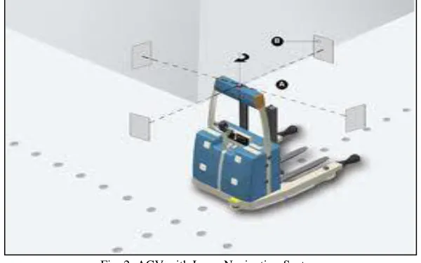
Let us consider case study of Laser Navigation AGV. To incorporate the increasing need of flexibility new wireless industrial guidance systems are installed and are known as free ranging AGVs which permit the AGV to operate without physical guide paths similar to human including navigation and manoeuvring.
They are simple and facilitate guide path modification when new stations or flows are added. The most popular free ranging AGV is the laser navigation system which provides their position and orientation with the help of fixed reflectors located in the workplace (Herrero‐Pérez D, Decentralized Traffic Control for Non‐Holonomic Flexible Automated Guided Vehicles in Industrial Environments., 2011).
Fig. 2: AGV with Laser Navigation System
There are two problems which are observed in this particular system
1) In case of insufficient reflectors the laser device does not provide any position estimates. 2) The position estimates provided are not very frequent that is at low rates
estimated speeds over elapsed time and course(Herrero D, 2013)(Herrero‐Pérez D, Decentralized Coordination of Autonomous AGVs in Flexible Manufacturing Systems. , 2008)(Hoshino S, 2010).
As per the case study two experiments are considered the first experiment is the navigation experiment which aims to evaluate the trajectory run using only dead reckoning information whereas the position is estimated by laser navigation system. A closed loop trajectory and a zigzag pattern is followed by the AGV.
Fig. 3: The Navigation Experiments using the Industrial Guidance System
1) A Closed‐Loop Trajectory. 2) Tracing Zigzag Pattern.
It is observed that in the first figure Dead reckoning trajectory provides similar position estimates as laser device but this result is only observed when the system is travelling straight whereas the position error increases when the vehicle turns (Nishi T, 2010). In the second figure position error significantly increases on the turns and also position estimates provided by the laser device are less accurate when the vehicle turns. This is of utmost importance because the load transfer operations usually require turning and hence these position estimates induce collisions affecting the overall system robustness.
Fig. 4: The Docking Experiment
1) The trajectory to follow and the actual trajectory 2) The positioning error
V.
CONCLUSIONS
There can be various methods that can incorporated in a system to increase its robustness is to add any type of fault tolerant mechanism which will allow the AGV to run safely even when there are obstacles, breakdowns or any change in delivery schedules. It is observed that laser navigation is less accurate especially when the vehicle is turning which compromises the stability and does not provide accuracy, repeatability and reliability.
The issue in use of only the position estimates provided by the laser device is dual: they are provided at a low rate and are less accurate when the vehicle is moving, particularly when it turns. The first issue compromises the stability of the path tracker approach, while the second does not permit the vehicle to operate with the high condition of accuracy, repeatability and reliability which is required by some operations. It is well known that dead‐reckoning cannot provide robust and accurate position estimations because slip and drift errors are uncontrolled. The experimental validation shows that the implementation of the filter allows complex manoeuvres to be achieved with bounded errors in positioning and bearing, which are not possible using only one of the sources of information.
Therefore the robustness of any AGV system can be increased by implementing a filter which combines results from dead reckoning and laser navigation systems hence reducing position errors and imparting flexibility and robustness to the AGV system.
REFERENCES
[1] Zang a, M. F. (2003). A review of robust optimal design and its application in dynamics. 315-326.
[2] Fowlkes WY, C. C. (1995). Engineering methods for robust product design: using Taguchi methods in technology and product development.
[3] Herrero D, V. J. (2013). Self‐Configuration of Waypoints for Docking Maneuvers of Flexible Automated Guided Vehicles. IEEE Trans. Autom. Sci. Eng., 470-475.
[4] Herrero‐Pérez D, M.‐B. H. (2008). Decentralized Coordination of Autonomous AGVs in Flexible Manufacturing Systems. . 3674-3679.
[5] Herrero‐Pérez D, M.‐B. H. (2011). Decentralized Traffic Control forNon‐Holonomic Flexible Automated Guided Vehicles in Industrial Environments. Advanced Robotics , 739-763.
[6] Hoshino S, S. H. (2010). Multirobot Coordination for Flexible Batch Manufacturing Systems Experiencing Bottlenecks. . IEEE Trans. Autom. Sci. Eng. ,887-901. http://www.isixsigma.com/library/content/c020311a.asp). (2011, March 02). Retrieved December 2014, from www.isixsigma.com.
[7] Nishi T, M. R. (2010). Petri Net Decomposition Approach to Optimization of Route Planning Problems for AGV Systems. . IEEE Trans. Autom. Sci. Eng. ,523-537.
[8] Rajesh Jugulum, D. D. (2007). Towards A taxonomy of concepts designs for improved robustness .Journal of Design Engineering , 139-156. SA, R. (2000). Conflict Resolution in AGV systems . IIE Trans , 647-59.