Dynamic Modeling and Analysis of DFIG based
Wind Turbine for Variable Wind Speed
Meera G. S N.A Divya
PG Scholar Assistant Professor
Department of Electrical Electronics Engineering Department of Electrical Electronics Engineering Mar Baselios College of Engineering and Technology Mar Baselios College of Engineering and Technology
Abstract
Over the last ten years, the global wind energy capacity has increased rapidly and became the fastest developing renewable energy technology. But unbalances in wind energy are highly impacting the energy conversion and this problem can be overcome by using variable speed wind turbines. Doubly Fed Induction Generator (DFIG) based Wind Energy Conversion Systems (WECS) are gaining tremendous attention nowadays. In this paper the mathematical modeling of wind turbine is simulated in MATLAB and the results are analyzed for both fixed and variable wind speed. Also dynamic modeling of DFIG has been simulated using MATLAB/SIMULINK and the dynamic behavior of DFIG driven by wind turbine is simulated for variable wind speed.
Keywords: WindTurbine, Doubly-fed induction generator, Wind Energy Conversion System.
________________________________________________________________________________________________________
I.
I
NTRODUCTIONIn the recent years, renewable energy systems have attracted the great interest because conventional sources of energy are limited and a number of problems associated with their use, like environment pollution, large grid requirements etc. Government of the whole world is forced for the alternative energy sources such as wind power, solar energy and small hydro-electric power [1]. Among the above given choices, wind energy is a realistic way of harnessing the natural energy. Wind energy has been intensively investigated in recent years in many different countries, which resulted in several different configurations like fixed speed system with a SCIG, the variable speed system with permanent magnet synchronous generator (PMSG) and the variable speed system with a DFIG to improve the efficiency, power rating, cost benefit effectiveness etc [2].
Wind is highly variable in nature, so variable speed Doubly Fed Induction Generator based WECS offers many advantages compared to the fixed speed squirrel cage induction generators, such as reduced converter rating, cost, losses in result of that an improved efficiency, easy implementation of power factor correction, variable speed operation and four quadrants active and reactive power control capabilities . Due to variable speed operation, total energy output is much more in case of DFIG-based WECS, so capacity utilization factor is improved and cost of per unit energy is reduced [3].
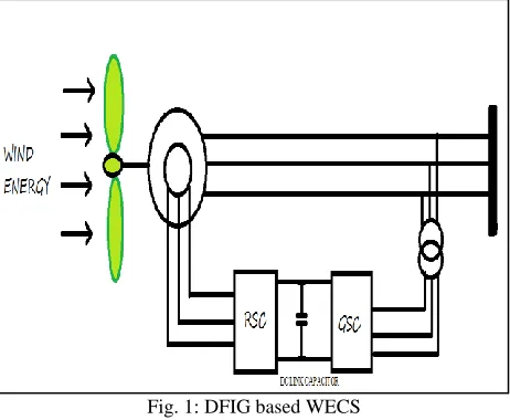
Fig. 1: DFIG based WECS
wind induction generators is their ability to supply power at constant voltage and frequency while the rotor speed varies. Hence DFIG became more popular in wind power applications. Again controlling the DFIG from the rotor side makes the control process more cost effective as the rotor converters have to deal with comparatively less power when connected at the rotor side than when connected at the stator side.
In this paper a mathematical modeling of wind turbine has been simulated using MATLAB/SIMULINK and the results are analyzed for fixed and variable wind speed. Also modeling and simulation of DFIG is done in MATLAB/SIMULINK platform and the dynamic behaviour of DFIG driven by wind turbine is simulated for variable wind speed.
II.
W
IND TURBINE MODELINGThe possible amount of wind power, which can be harvested by a wind turbine, is limited theoretically to 58% of total power content of the wind, considering Betz limit [4-5]. The wind turbine power coefficient is typically lower than 0.45.The generalized mechanical equation of the wind turbine is given as
e m s
r
S
B
wr
T
T
dt
dw
J
(1)In which,
J
Sis total inertia of the shaft,B
s is friction coefficient,T
m is the torque with wind origin andT
e is the electromagnetic torque produced by the generator. The generated torque is given byr m m
P
T
(2)m
P
is the amount of mechanical power generated from the wind turbine.
3,
5
.
0
AC
V
P
m
p
(3)ρ is the air density, A is the swept area, Cp is the coefficient of performance, λ is the Tip speed ratio.
3
V
R
m
(4)There are a number of approximations available for Coefficient of Performance (Cp).
0
.
4
5
0
.
006795
116
5176
.
0
21
t i pe
C
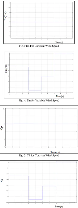
(5)The Cp for constant wind is 0.48. Fig.2 shows the SIMULINK model of wind turbine.
III.
M
ODELING AND ANALYSIS OF THE DOUBLY-
FED INDUCTION GENERATORA doubly-fed induction generator is as a standard wound rotor induction generator with its stator windings directly connected to the power grid and rotor connected to the power grid through a frequency converter [6-7]. The operation of DFIG can be analyzed using the classic theory of rotating fields and well known d-q model, as well as both three-to-two and two-to-three axes transformations.
The dynamic modeling of doubly-fed induction generator in synchronously rotating reference frame de–qe involves the following equations. s sd sd s sd
dt
d
I
R
V
(6) dq s sq sq s sq
dt
d
I
R
V
(7) rq r rd rd r rd
dt
d
I
R
V
(8) rq r rd rd r rq
dt
d
I
R
V
(9) The stator and rotor fluxes can be expressed as
rd sd
s
sd
L
I
MI
(10)rq sq
s
sq
L
I
MI
(11)sd rd
r
rd
L
I
MI
(12)sd rq
r
rd
L
I
MI
(13)The electromagnetic torque is expressed as
rd sq rq sd
em
pM
I
I
I
I
T
(14)The active and reactive power taken by the machine can be represented by the following equations.
ds ds qs qs
s
V
I
V
I
P
2
3
(15)
ds ds qs qs
s
V
I
V
I
Q
2
3
(16)
Where d and q subscripts stand for the d-axis and q-axis components, r and s subscripts stand for rotor and stator, V stands for the constant grid voltage ϕ stands for flux, R stands for resistance, I stands for current, ω stands for the utility frequency, p
stands for the number of pole pairs,
r stands for the rotational speed of the generator rotor,
r dr o ms
sl qr r qr r
qr
L
i
L
i
dt
di
L
i
R
V
(17)
IV.
S
IMULATION RESULTS AND DISCUSSIONFig.3 Tm For Constant Wind Speed
Fig. 4: Tm for Variable Wind Speed
Fig. 5: CP for Constant Wind Speed
Fig.5 shows the coefficient of performance (Cp) for constant wind speed in per unit and Fig.6 shows the Cp for variable wind speed. The wind speed is varied at 0, 3, 5 and 7 seconds.
Fig.7 to Fig.14 shows the simulation results of Doubly Fed Induction Generator driven by wind turbine for variable wind speed. The DFIG based wind turbine is simulated using MATLAB/Simulink. The stator of the DFIG is having three phase supply. Fig.7 shows the stator voltage.
Fig. 7: Stator Voltage
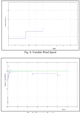
The response of the DFIG system is simulated for the case of step changes in the wind speed as shown in Fig.8. The variation of wind speed at 0, 0.5 and 1 sec is shown in Fig.8. From 0 to 0.5 wind speed is 4m/s, from 0.5 to 1 it is 8m/s and beyond 1 it is 10m/s.
Fig. 8: Variable Wind Speed
After the cut in speed the turbine starts generating power. When the wind speed increases the generator speed also increases [19-20]. When the wind speed is less than the rated speed rotor rotates at a speed less than the synchronous speed i.e. sub synchronous generating mode.
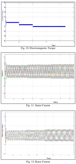
Fig. 10: Electromagnetic Torque
Fig. 11: Stator Current
Fig. 12: Rotor Current
Fig.9 shows the sub synchronous generating mode of DFIG for variable wind speed. Fig.10 shows that when wind speed increases the torque increases and as it is a generator the torque is negative.
Fig. 13: Slip
Fig. 14: Rotor Angle Theta
As the wind speed increases stator current and rotor current increases. The simulation results are shown in Fig.11 and Fig.12. Also when the speed of the generator rotor is less than the synchronous speed, the corresponding slip will be positive as shown in Fig.13. The rotor angle theta in electrical degrees is shown in Fig.14.
V.
C
ONCLUSIONIn this paper mathematical modeling of wind turbine has been simulated using MATLAB and the results are analyzed for both fixed and variable wind speed. Also the dynamic modeling of DFIG has been simulated and the results are analyzed for variable wind speed. The results shows that the variation of wind speed induces variation in the performance of the machine.
A
PPENDIX Table – 1 Machine Details Parameter Rated Values Power(kW) 30 Voltage(V) 415 Current(A) 100 No of poles 4 Frequency(Hz) 50R
EFERENCES[1] Niassati, N., et al. "A new maximum power point tracking technique for wind power conversion systems." Power Electronics and Motion Control Conference (EPE/PEMC), 2012 15th International. IEEE, 2012.
[2] M. Liserre, R. Cardenas, M. Molinas, and J. Rodriguez, “Overview of multi-MW wind turbines and wind parks,” IEEE Trans. Ind. Electron., vol. 58, no. 4,
pp. 1081–1095, Apr. 2011.
[3] S. Muller, M. Deicke, and R. W. De Doncker, “Doubly fed induction generator systems for wind turbines,” IEEE Ind. Appl. Mag., vol. 17, no. 1, pp. 26–33,
May–Jun. 2002.
[4] Verdornschot M. Modeling and control of wind turbines using a continuously variable transmission [Master’s thesis]. Eindhoven: Eindhoven University of
Technology, Department of Mechanical Engineering; 2009.
[5] A.Tapia, G.Tapia, J.Ostolaza, “Modeling and Control of a Wind Turbine Driven Doubly Fed Induction Generator”, IEEE Trans on Energy
Conv.Vol-18,No-2,June-2003.
[6] Ozpineci, Bhurak, and Leon M. Tolbert. "Simulink implementation of induction machine model-a modular approach." Electric Machines and Drives Conference, 2003. IEMDC'03. IEEE International. Vol. 2. Ieee, 2003.
[7] G. Abad, G. Iwanski, J. López, L. Marroyo, and M. A. Rodríguez, Doubly Fed Induction Machine: Modeling and Control for Wind Energy Generation
Applications. Hoboken, NJ: Wiley, 2011.
[8] Pati, Swagat, and Swati Samantray. "Decoupled control of active and reactive power in a DFIG based wind energy conversion system with conventional PI
controllers." Circuit, Power and Computing Technologies (ICCPCT), 2014 International Conference on. IEEE, 2014.
[9] M.Aktarujjaman, M.E.Haque, K.M.Muttaqi, M.Negnevitsky, and G.Ledwich, sch.of.Eng., Univ.of Tasmania, Hobart, TAS, “Control Dynamics of a
Doubly Fed Induction Generator Under Sub and Super-Synchronous Modes of Operation” IEEE Conference Proceedings, 20-24 July 2008, pages 1-9.
[10] C. Yik Tang, Y. Guo, and J. N. Jiang, “Nonlinear dual mode control of variable–speed wind turbines with doubly fed induction generators”,IEEE Trans on
Control Systems Technology, in press.
[11] D.Chwa , Kyo-Beum “ Variable Structure Control of the Active and Reactive Powers for a DFIG in Wind Turbines ”, IEEE Trans on
IndustrialApplications.Vol-46,No-6,Nov-Dec-2010.
[12] An Improved Control Strategy of Limiting the DC-Link Voltage Fluctuation for a Doubly Fed Induction Wind Generator” by Jun Yao, Hui Li, Yong Liao,
and Zhe Chen, Chongqing University, Chongqing, China. IEEE transactions on power electronics, vol. 23, no. 3, may 2008.
[13] W. Qiao, W. Zhou, and R. G. Harley “Wind speed estimation based sensorless output maximization control for a wind turbine driving a DFIG” IEEE Trans
on Power Electronics, vol. 23, no. 3, pp May 2008.
[14] Raza Kazmi SM, Goto H, Hai-Jiao G, Ichinokura O. Review and critical analysis of the research papers published till date on maximum power point tracking in wind energy conversion system. In: 2010 IEEE Energy Conversion Congress and Exposition (ECCE). 2010. p. 4075–82.
[15] Hui J, Bakhshai A. A new adaptive control algorithm for maximum power point tracking for wind energy conversion systems. In: IEEE Power Electronics
Spe-cialists Conference PESC. 2008. p. 4003–7.
[16] W. Qiao, W. Zhou, J. M. Aller, and R. G. Harley, “Wind Speed Estimation Based Sensorless Output Maximization Control for a Wind Turbine Driving a
DFIG,” IEEE Trans. Power Electron., vol. 23, no. 3, pp. 1156–1169, May 2008.
[17] Abdullah, M. A., et al. "A review of maximum power point tracking algorithms for wind energy systems." Renewable and Sustainable Energy Reviews 16.5 (2012): 3220-3227.
[18] Kazmi SMR, Goto H, Hai-Jiao G, Ichinokura O. A novel algorithm for fast and efficient speed-sensorless maximum power point tracking in wind energy
con-version systems. IEEE Transactions on Industrial Electronics 2011;58:29–36
[19] Hansen, Anca D., et al. "Overall control strategy of variable speed doubly-fed induction generator wind turbine." Wind Power Nordic Conference. 2004.