STRUCTURE OPTIMIZATION OF GRIPPER MANIPULATOR USING OPTISTRUCT
V.C.BARAVKAR, Scholar, ME Design,
V. S. AHER,
Professor, Amrutvahini College of Engineering, Sangamner, India
ABSTRACT:
This paper deals with optimization of Gripper engine block manipulator. The Gripper provides the holding to the engine block is mounted on the Subject manipulator. There are two brackets to hold engine block. Analysis is done on one gripper and the results are considered for other one gripper. Analysis is done for only Gripper. On production line first clamp engine block, lift engine block then rotate 180º and keep on same position on assembly line its two degree freedom. The gripper manipulator is a two degrees-of-freedom manipulator, with one linear hoist and rotates with help pneumatic motor. FEM Optimization is useful in designing the new shape and size with reduced design time. It also helps to reduction of unnecessary material and thereby weight of the component decreases. To optimized design with the help of hyper mesh, hyper works and optistuct solver for optimization the design. A gripper is used to hold work piece accurately & stable during the engine block handling. Because of increase in global competition we must decrease the cost and at the same time increase the performance and achieve all these with time constraint. Topology optimization tool is used not only designing gripper bracket analysis to get better design with less time but also helps in the reduce of unwanted material. Gripper engine block Structure is optimized to minimize the mass and the stress requirements.
KEYWORDS: Analysis, Gripper engine block, Topology Optimization, Hyper mesh, Optistruct Solver, Hyper view.
INTRODUCTION:
Increasing competition between special purpose machine manufacturers has forced the development of new products to focus upon more efficient and effective design. This results to competitive product, increased sales and ultimately increased profits. The work of this exercise is to develop a do things right at first time approach to the design of a Special purpose machine manufacturing s machine. When this method has been
defined, a detailed concept, which matches the structural targets, can be developed from initial styling surfaces with minimal design iterations. Topology optimization can be used to ensure that material is spread throughout the structure in an efficient manner to maximize stiffness and
minimize mass.[7]The application of topology
optimization to structural design provides an extremely fast route to ensuring the machine body structure meets or exceeds the relevant structural targets.
V.C.Bbaravkar is with the Amrutvahini College of Engineering, Sangamner. ME (Design Engineering) (e-mail:[email protected]).
V. S. Aher Assistance Professor, BE (Mechanical), M-Tech (Design), Ph.d (Persuing) PG Coordinator (Design Department) Amrutvahini College of Engineering, Sangamner.
Three basic functions in optimization work.
1. Aim of Designer to want maximize and minimize. I.e. minimized weight of model and maximized strength of model.
2. The set of variables which are suffer the model function. The input is model variable parameter used to know shape and dimension of model.
3. Constrains for model. Model displacement, weight, size, shape etc. In sheet metal design we want to reduce weight of model and constrain is shape.[6]
Structure optimization can be categorized into three different areas a. Size optimization b. shape optimization c. topology optimization. Optimization tool used to structure optimization. The main of structure optimization to used material distribution in optimum way. in structure optimization functions are to minimized static displacement to reduce weight of product and the compliance. The most important is to reduce mass of product and size of component.[6]
In size optimization shows the ideal product model like material value, cross section area and material thickness. Size optimization mainly used structure optimization. we know the shape of model to optimized the structure by adjust size of model. The design parameters are size for structure elements. During structure optimization design variables are consider as rod diameter, sheet metal thickened and beam thickness.
Fig. 2. Optimization in shape.
SHAPE OPTIMIZATION:
When we design new component to minimize the weight of product we make of holes, beams.
In shape optimization mean not make holes model or structure. In shape optimization design parameters are thickness which distribute along structure member like diameter of hole. In shape optimization the design parameters are affect the many nodes and elements. In topology size optimization design parameter are affect one variable parameter.[1]
Fig. 3. Optimum distribution of material.
Topology optimization is used mostly in structure optimization. The main aim of topology optimization is optimum used of material. During solving problem model discredited by finite element method and model divided in infinite to finite element in nodes and elements. When work on model we do not know the number of holes etc. The purpose is to find out the optimum distribution of material. it help to produce new innovative concept design. The benefit topology optimization is accuracy, good performance, less weight and innovative product design.[2]
LITERATURE REVIEW:
M. Vijay Kumar Reddy, P. Chitti Babu, K. C. K. Bharathi “Analysis of Light Motor Vehicle Component Using Topology Optimization Method”, International Journal of Emerging Technology and Advanced Engineering, Volume 4, Issue 1, January 2014.
Due to the increase in global competitive market, automotive designs are pushed to the limits to decrease the cost and at the same time increase the stiffness to mass ratio and performance. Above all, the biggest constraint is to achieve all these with reduced design time. In order to get better designs, industries are using tools like FEM Optimization; these techniques are useful in designing the new shape and size with reduced design time. It also helps in the reduction of unwanted material and thereby mass of the component decreases respectively.
Ms. Nazia .S. Ansari,Mr. Naushad Ansari,Mr. Vinay Kulkarni, “Structural Optimization of Drive Unit Bracket Using OptiStruct” Altair technology conference,2013.
This paper describes development of a Finite element model and subsequent analysis and simulation of Drive Unit Bracket Assembly consisting of structural members which are designed using basic principles of structural design. Topology & Size optimization is applied to Drive Unit Bracket Assembly considering volume as the objective along with stress constraints. Manufacturing constraints are considered to provide the manufacturability and interpretable design proposal. From the interpretations of Topology & Size optimization, one conservative design is proposed. Drive Unit Bracket Structure is optimized to minimize the mass and the stress requirements.
R. Jaina , P. Tandona, M. Vasantha Kumar, “Optimization methodology for beam gauges of the bus body for weight reduction” Applied and Computational Mechanics 8 (2014) 47–62
investigation on a loaded transport. It additionally performs auxiliary solidness examination and vibration investigation for security of the transport structure. This work unfurls an incorporated philosophy to the transport makers to streamline the auxiliary weight for enhancing the fuel productivity, static and element wellbeing, and powerful outline. The work is executed by making a limited component model of the transport and improving in Hyper Works environment. The procedure assists in weight decrease alongside change in execution parameters.
GENERAL ARRANGEMENT:
Layout for engine block manipulator 3D in catia
OBJECTIVE:
1. Design of general assembly and detailed design of gripper engine block manipulator components.
2. Gripper is the critical components and analysis of that component.
3. Optimized the critical components.
METHODOLOGY:
To optimize gripper engine block manipulator we need to develop concept design of gripper in this we must know where and how this gripper is engaged with engine block. According to that the CAD model of gripper is developed. This CAD model is continuing object have finite degree of freedom we cannot solve this problem in this format. In FEA we can reduce degree of freedom from infinity to finite is calls descritization i.e. meshing. Which have number of nodes and elements, after descritization we can solve this problem in optistruct12.0. This result can be interpreted in hyper work. Where strain energy is maximum at that portion we can remove unnecessary material. We can optimize model with shape and size. This optimization technique gives us good design, Better Performing, Lightweight and Innovative Designs and at less time consuming [4]
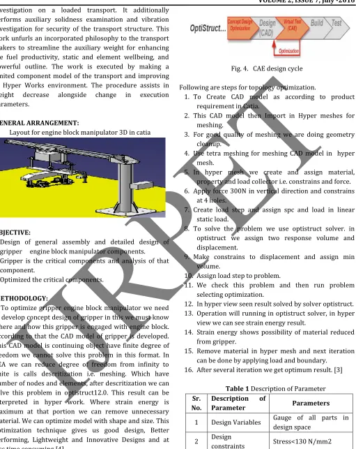
An overview of the CAE design cycle can be seen in fig.4
Fig. 4. CAE design cycle
Following are steps for topology optimization.
1. To Create CAD model as according to product requirement in Catia.
2. This CAD model then Import in Hyper meshes for meshing.
3. For good quality of meshing we are doing geometry cleanup.
4. Use tetra meshing for meshing CAD model in hyper mesh.
5. In hyper mesh we create and assign material, property and load collector i.e. constrains and force. 6. Apply force 300N in vertical direction and constrains
at 4 holes.
7. Create load step and assign spc and load in linear static load.
8. To solve the problem we use optistruct solver. in optistruct we assign two response volume and displacement.
9. Make constrains to displacement and assign min volume.
10. Assign load step to problem.
11. We check this problem and then run problem selecting optimization.
12. In hyper view seen result solved by solver optistruct. 13. Operation will running in optistruct solver, in hyper
view we can see strain energy result.
14. Strain energy shows possibility of material reduced from gripper.
15. Remove material in hyper mesh and next iteration can be done by applying load and boundary.
16. After several iteration we get optimum result. [3]
Table 1 Description of Parameter Sr.
No.
Description of
Parameter Parameters
1 Design Variables Gauge of all parts in design space
2 Design
constraints Stress<130 N/mm2
MESHING FOR CAD MODEL:
Before we start meshing we need to clean up all model i.e. geometry clean up. In this we remove or add some edges. We split the surface in different parts so that it will easy to meshing. After doing geometry cleanup we get accurate result of meshing. One the basis of quality of meshing the accuracy of results is depend. [2]
Fig. 5. CAD model of gripper engine block manipulator.
MATERIAL SELECTION:
The material was specified as mild steel as a result the material value for young’s modulus 210GPA and poisons ratio 0.33 this parameters are required of the topology optimization study.
Table 2 Specifications of Material
Sr. No. Description Value
1 Young’s modulus 210Mpa
2 Poisson’s ratio 0.3
3 Density 7900 Kg/mm3
4 Wield strength 260Mpa
TETRA MESHING:
This meshing method is most commonly used. Quad or tria meshing is carried out on the surface of the geometry, quad split in to tries and then convert to tetras.
Step1. Study the geometry. Step2. Separate surfaces. Step3. Combine the mesh.
Step4. Quality check for triangular element. Step5. Convert tria mesh to tetra.
Step6. Quality check for tetra elements.
Step 7.free free run or otherwise linear static analysis with constrains.[5]
Table 3 Description of elements Before optimization
SR NO DESCRIPTION NO
1 Total no of elements 56940
2 Total no of nodes 14409
Fig. 6 Meshing to component.
BOUNDARY CONDITIONS:
In FEA, when we need accurate output it is important to maintain proper boundary conditions. This is important in for topology optimization. This Boundary condition will be the based or the material of distribution.
CONSTRAINTS AND LOADS:
In this work, gripper engine block consists of five holes, these five holes are considered to be constraints. And remaining four holes acting point load on each gripper engine block in downward direction is 5N, as shown in fig 7.
Fig 7. Boundary conditions applied.
When we apply constrains and loads, and run this work using Optistruct. The optistruct solver shows result maximum displacement and stress. The output can be seen in hyper view. Fig 8 shows the displacement occur in the gripper engine block manipulator and Fig 9 shows the maximum stresses occur in the gripper engine block manipulator before optimizing the component.
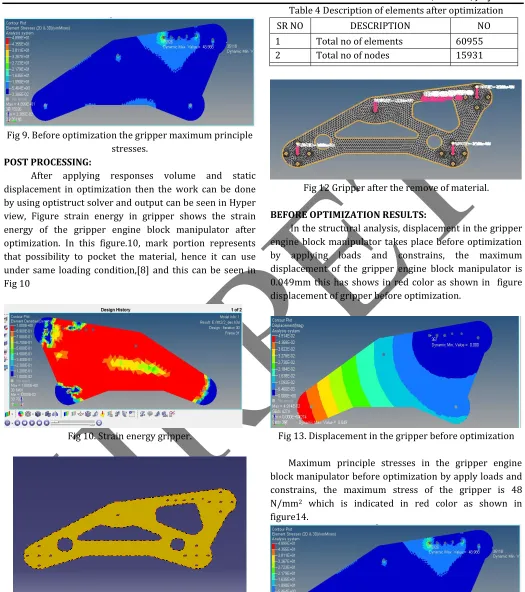
Fig 9. Before optimization the gripper maximum principle stresses.
POST PROCESSING:
After applying responses volume and static displacement in optimization then the work can be done by using optistruct solver and output can be seen in Hyper view, Figure strain energy in gripper shows the strain energy of the gripper engine block manipulator after optimization. In this figure.10, mark portion represents that possibility to pocket the material, hence it can use under same loading condition,[8] and this can be seen in Fig 10
Fig 10. Strain energy gripper.
Fig 11. Strain energy gripper after remove of material.
The fig.11 help us to remove unnecessary material from gripper with help of hypermesh we can remove material from model which in fig 12
Table 4 Description of elements after optimization
SR NO DESCRIPTION NO
1 Total no of elements 60955
2 Total no of nodes 15931
Fig 12 Gripper after the remove of material.
BEFORE OPTIMIZATION RESULTS:
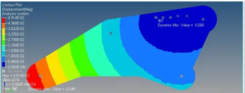
In the structural analysis, displacement in the gripper engine block manipulator takes place before optimization by applying loads and constrains, the maximum displacement of the gripper engine block manipulator is 0.049mm this has shows in red color as shown in figure displacement of gripper before optimization.
Fig 13. Displacement in the gripper before optimization
Maximum principle stresses in the gripper engine block manipulator before optimization by apply loads and constrains, the maximum stress of the gripper is 48 N/mm2 which is indicated in red color as shown in figure14.
RESULTS AFTER OPTIMIZATION:
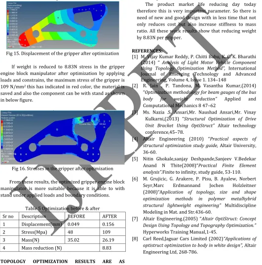
If weight is reduced to 8.83N displacement of the gripper engine block manipulator after optimization by applying loads and constrains, the maximum displacement of the gripper is 0.156 mm this has indicated in red color, the material is saved and also the component can be with stand as shown in below fig.15.
Fig 15. Displacement of the gripper after optimization
If weight is reduced to 8.83N stress in the gripper engine block manipulator after optimization by applying loads and constrains, the maximum stress of the gripper is 109 N/mm2 this has indicated in red color, the material is saved and also the component can be with stand as shown in below figure.
Fig 16. Stresses in the gripper after optimization
From these results, the optimized gripper engine block manipulator is more suitable because it is able to with stand under applied loads and boundary conditions.
Table 5 Optimization before & after
Sr no Description BEFORE AFTER
1 Displacement(mm) 0.049 0.156
2 Stress(Mpa) 48 109
3 Mass(N) 35.02 26.19
4 Mass reduction (N) 8.83
TOPOLOGY OPTIMIZATION RESULTS ARE AS FOLLOWS:
Stress 109 N/mm2 and displacement is 0.156 mm. These satisfy the properties of actual model before
optimization all these state that model is optimized model.[3]
CONCLUSIONS:
There are two different phases of this work 1. Good design.
2. Design time.
The product market life reducing day today therefore this is very important parameter. So there is need of new and good design with in less time that not only reduces cost but also increase stiffness to mass ratio. All these work results show that reducing weight by 8.83N per gripper.
REFERENCES:
[1] M. Vijay Kumar Reddy, P. Chitti Babu, K. C. K. Bharathi (2014) “ Analysis of Light Motor Vehicle Component Using Topology Optimization Method”, International Journal of Emerging Technology and Advanced Engineering, Volume 4, Issue 1. 134–148
[2] R. Jain , P. Tandona, M. Vasantha Kumar,(2014) “Optimization methodology for beam gauges of the bus
body for weight reduction” Applied and
Computational Mechanics 8 47–62
[3] Ms. Nazia .S. Ansari,Mr. Naushad Ansari,Mr. Vinay Kulkarni,(2013) “Structural Optimization of Drive Unit Bracket Using OptiStruct” Altair technology conference,45–78.
[4] Altair Engineering (2010) “Practical aspects of structural optimization study guide, Altair University, 36-60.
[5] Nitin Ghokale,sanjay Deshpande,Sanjeev V.Bedekar Anand N Thite(2008)“Practical Finite Element
analysis”.Finite to infinity, study guide, 53-110. [6] M. Grujicic, G. Arakere, P. Pisu, B. Ayalew, Norbert
Seyr,Marc Erdmannand Jochen Holzleitner
(2008)“Application of topology, size and shape optimization methods in polymer metalhybrid structural lightweight engineering” Multidiscipline Modeling in Mat. and Str.436-60.
[7] Altair Engineering.(2005) “Altair OptiStruct: Concept Design Using Topology and Topography Optimization.”
Hyperworks Training Manual,1-45.