ISSN (Online): 2320-9364, ISSN (Print): 2320-9356
www.ijres.org Volume 4 Issue 9 ǁ September. 2016 ǁ PP. 52-58
Geant 4 Study of Concrete Density Measurement Using Gamma
Backscattering Technique
Trịnh Hoa Lang
1,Le Cong Hao
2,Chau Van Tao
1,Huynh Dinh Chương
2,Truong
Thi Hong Loan
2,Nguyen Thi My Da
2,Le Quoc Bao
2,Le Thi Ngoc Trang
2,Tran
Kim Tuyet
2,Nguyen Thi Truc Linh
2,Luong Thanh Tung
1,Do Trong Vien
11
Nuclear Physics Department , Physics And Engineering Physics Faculty, University Of Sciences –Vnuhcm
2Nuclear Technique Laboratory, University Of Sciences –Vnuhcm
Abstract: In this work, the gamma backscattering is studied in measurement of concrete density by using Scintillation detector NaI(Tl). The gamma backscattering spectrum of the various concrete densities are analyzed to figure out the characterized parameter which is sensitive to the density and the component of concrete. The GEANT4 simulation is preliminarily used to study the distribution of the Compton scattering and the multiple scatterings in the concrete. The optimal experimental geometry is set up by these simulation results.
Keyword: backscattering, gamma,Compton, concrete, geant4, MCNP.
I. INTRODUCTION
Nuclear density gauges are used by many contractors, engineers and highway departments for compaction control of soil, aggregate, concrete and full asphalt. Surface nuclear gauges use the interaction of gamma radiation with matter to measure density through direct transmission or backscatter. The backscatter is a rapid and nondestructive means of testing materials that are approximately 10 cm (4 in.) in depth. The gamma source and the detectors remain inside the gauge, which rests on the surface of the test material. Gamma rays from the density source enter the test material. Those that are scattered back toward the detectors are counted, determining the density count for the material. This means of testing is usually used to determine density on layers of asphalt and concrete.
Almost the detectors of nuclear density gauges are ionized chamber, which is used to collect the entire backscattered count. The assumption that if the ion chamber is replaced by scintillation detector NaI(Tl) and the whole count is replaced by the gamma spectrum, what we can study from these differences. It motivates us to find out the more advantage results of gamma backscattering spectrum by the scintillation detector rather than the total backscatter count by the ion chamber. The other problem is that the geometry design of the radioactive source and the detector in the commercial Nuclear Gauges is really optimized.
In this work, the dependences of the backscattering gamma in the concrete densities, and the different scattering angles and the angles of the detector and the target using the detector NaI(Tl) are sophisticatedly studied by the GEANT4 simulation.
II. THEORY, MATERIALS AND METHODOLOGY
The overview Compton scattering theory
Gamma density logging uses the concept of gamma ray backscattering to measure the electron density of the materials in the vicinity of the gamma source. A radioactive source emits gamma rays into the target materials. These gamma rays collide with electrons in the target materials, lose some of their energy and change direction in a manner called Compton scattering. Some of those particles are scattered into a detector. The number of these interactions is directly related to the number of electrons in the target materials. Thus, the electron density of the target materials is measured.
The energy of a scattered gamma, which depends on the scattering angle, is given by [2]
cos
1
c
m
E
1
E
E
2 e
0 0
(1)
where E0 and E are initial and final gamma energy, is the angle of scattering, and mec2 is the electron’s rest energy.
electrodynamics’ derivation of the scattering cross section in 1929, whilst explaining the puzzling asymmetry between forward and back scattering, contains no parameter specific to the scattered target[2]:
2 e 0 0 2 e 1 1 2 2 0 0 2 0 2 0 KN C
c
m
E
k
and
c
m
E
k
electron
sr
cm
k
k
k
k
k
k
r
2
1
d
d
sin
(
)
(2)
where r0 is the classical electron radius.
Integration of Equation (2) over all angles gives the total Klein-Nishina’s cross section
,
(
)
ln
ln
2 12 2
2 0 KN
C
cm
electron
k
2
1
k
3
1
k
2
k
2
1
k
k
2
1
k
2
1
k
1
2
k
k
1
r
2
(3)This scattering cross section can be considered as to be proportional to the intensity of the scattered gamma which can be measured by experiment at the different scattering angle.
The Klein-Nishina’s formula for Compton scattering from atomic electrons assume that the electrons are free and at rest, which is a good approximation for photons of the order of 1 MeV or higher, particularly for low-Z target materials. Binding corrections have usually been treated by the impulse approximation or by Waller Hatree theory[7], taking account not only of the K-shell, but all of the atomic electrons. This involves applying a multiplicative correction, the so-called “incoherent scattering function”, S(q,Z), to the differential Klein-Nishina’s formula,
d
d
Z
q
S
d
d
BDC KNC,
(4)where Z is atomic number. The momentum transfer, q, is related to the photon energies and deflection angle, , according to [5]
k
k
2
k
k
cos
q
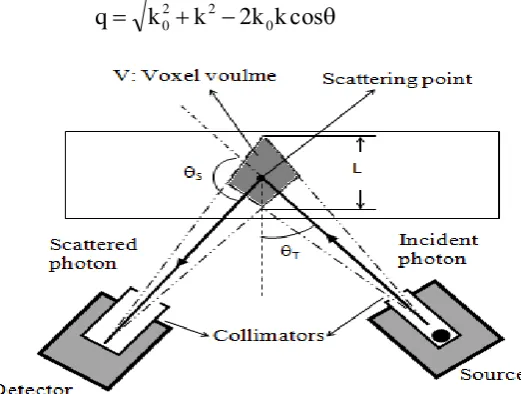
20 2 0 (5)Figure 1
. Schematics of the backscattering geometry
where q is in mec 2
unit. Incoherent scattering functions have been surveyed and studied by Hubbelle et al [3,4] and are presented for all elements Z=1 to 100, for photon energies 100 eV to 100MeV. The ratios of
cBD to cKN for photon energies of above 100keV are close to one. So for incident gamma of energy greater than 100keV, the binding corrections can be ignored.
- Gamma backscattering technique for measurement of object’s density
small attenuation by the air between the object and the backscatter system can be ignored then the total Compton scatter intensities can be given as[1] :
e s
CBD C 0 p 0 0
C
V
A
E
M
d
d
E
A
E
I
q
Z
I
,
(6)I0 is the primary radiation flux (in photons/sec); E0 is the energy of the primary radiation; Ap(E0) =
exp[-(E0)x] is the attenuation of the primary photons between source and voxel, μ(E0) is the mass attenuation coefficient of the material for photons of energy E0, ρ is the density of the target, and x is the length of the incoming photon path in the target; ρe is the electron density at scattering point in voxel; V is voxel volume; As(E) = exp[-(E)x] is the attenuation of the scatter photons between voxel and detector, x is the length of the scattered photon path in the target; is the detector solid angle (in sterian, sr); MC is the multiple scatter component whose effect can only be neglected when the mean free path length, 1/, of the photon is much greater than a length dimension, L, characterising the object (scattering volume). The electron density, ρe , at the scattering point is proportional to the physical density ρ according to the formula
A
Z
N
Ae
(7)Where NA is Avogadro’s number, Z is the atomic number, and A is the atomic weight. The schematic diagram of backscatter geometry of the experimental arrangement is shown in Figure 1.
According to equation (6) we can expect an unambiguous interpretation of the signal IC as a function of material density at the scattering point. Nonhomogeneous materials (or those with irregular surfaces) present a different problem.
The multiple scatter components are comparative to the single scatter component in the term of length dimension L. When L is increased, the multiple scatter components are increased and the single scatter component is decreased. The problem is how to determine the multiple scatter contribution in the dimension length and at what dimensional length the multiple scatter effect is significant. It means that the multiple scatter is the function of L, MC (L). However, L can be changed by the geometry configuration of the target, the detector and the gamma source, i.e.; L is the function of the angle, T, between the target and the incoming photon, and the scattering angle, S. So the multiple scattering can be given in the function of the scattering angle and the angle of target and incident photon, MC(T,S). The analytical form of MC(T,S) can be studied by the GEANT4 simulation and the experiment.
The equation (6) can be rewritten as:
S
T S
C
T S
C
Z
q
I
M
I
,
,
,
(8)Where IS is the single scattering intensity component which is the first term in the equation (6)
V
A
E
d
d
E
A
E
I
I
e sBD C 0 p 0 0 S T
S
,
(9)The equation (8) and (6) are used to study the dependences of the single and multiple scattering components on the density of material. Therefore, the density of materials can be more accurately estimated by the total Compton scattering.
- The concrete materials are mixing of Portland cement, sand, gravel and water in the certain proportion. Portland cement is composed of four major oxides: lime (CaO), silica (SiO2), alumina (Al2O3), and iron (Fe2O3). Furthermore, Portland cement contains a small amount of magnesia (MgO), alkalizes (Na2O and K2O), and sulfuric anhydrite (SO3).
The sand mainly contains silica. There are two kinds of the gravel: carbonate gravel and macma gravel. The carbonate gravel essentially consists of 85% carbonate and 15% magnesia. The macma gravel is composed of seven major oxides: silica (SiO2), alumina (Al2O3), iron (Fe2O3), iron (II) oxide (FeO), lime (CaO), alkalizes (Na2O), and magnesia (MgO).
- The method of gamma backscattering spectrum analysis: single and multi gamma scattering in the concrete.
These parameters can be peak to the total ratio of the single or multi scattered spectrum, or can be the single scattered peak to the multi scattered peak.
These assumptions will be studied and selected by the preliminary simulation of the gamma backscattering in the concrete.
III. RESULTS AND DISCUSSIONS
The gamma backscattering spectrum in the concrete PC30-100 is studied in the term of the scattering angle, S, and the angle between the target and the incident gamma, T, by using GEANT4 code. The simulation setup consists of the Cs-137 source of gamma energy 662 keV, the scintillation detector NaI(Tl) 2 inch x2 inch, and the concrete target PC30-100. The radioactive source is contained in the lead collimator whose the inner radius is 1cm. The detector is also contained in the lead collimator whose the inner radius is 2 inch.
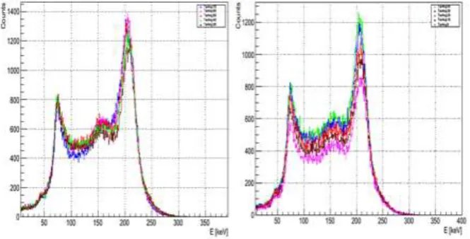
The results of ideal backscattering spectrum simulation of the various scattering angles show that the tendency of the total scattering spectrum is good agreement with the Klein-Nishina’s theory as given in the figure 2. The single and multi scattered gamma spectrums are separated from the simulation results.
The single scattered component is decreased when the scattering angle is decreased. If the material density is considered as dependence on the single scattering then the selection of the best scattering angle is 1300. The multi scattered component is increased when the scattering angle is decreased.
Figure 2. The simulation spectrum of the gamma backscattering of concrete PC30-100 at the scattering angles
S 90, 100, 110, 120, and 130 degree, and the target angle T 50 degree.
Figure 3. The simulation spectrum of the gamma backscattering of concrete PC30-100 at the target angles T 70, 60, 50, 40, 30, 20, 10, and 0 degree, and the target angle S 130 degree
.
The competition of the multi and single scattered components is also occurred when the target angle T is changed from 0 to 70 degree. The backscattering simulation spectrum is shown in the figure 3. This result turn out that the best backscattering spectrum is obtained at the target angles from 40 to 50 degree.
By these results, the scattering angle and target angle which is used in the simulation of gamma backscattering of concrete are 1300 and 500 respectively.
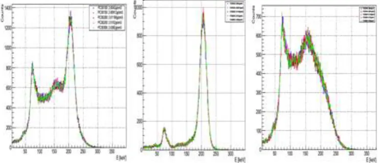
Figure 4. The simulation spectrum of the gamma backscattering of the cement, sand, gravel macma and water at the target angles T 50 and the target angle S 130 degree. From left to right, there are total, single and multi
backscattering spectrums.
The simulation results show that the different density is indicated by the gamma backscattering spectrum. These densities do not linearly depend on total count of the gamma backscattering as shown in the figure 4. The single scattering component cannot sensitively respond to the change of density. This obviously indicates in the figure 4. The multiple scattering component is significantly sensitive to the density. So it can be used to predict the density of material.
Then, the various concrete such as Portland concrete PC30 of 100, 150, 200, 250 and 300 of the different densities, are simulated as shown in the figure 5.
Figure 5. The simulation spectrum of the gamma backscattering of concrete PC30-100, 150, 200, 250, and 300 at the target angles T 50 and the target angle S 130 degree. From left to right, there are total, single and multi
backscattering spectrums.
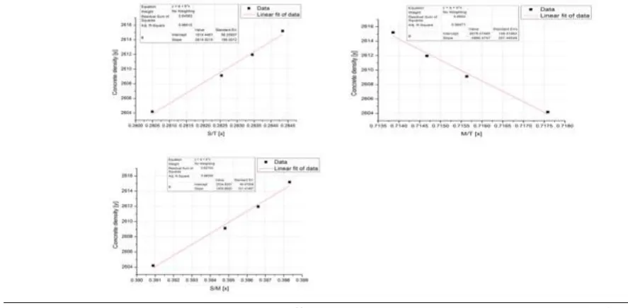
From the total, single and multple gamma backscattering spectrums of the concrete of the different densities, they are also the same tendency as in the first results. The concrete densities do also not linearly denpend on the total, single and multiple counts of gamma backscattering as shown in the figure 6. But the densities linearly depend on the ratios of the single, multiple count to the total and the multiple to single count as shown in the figure 7.
Table 1. Total, single, and multi counts of gamma backscattering and the ratios of the single count to the total count, multi count to the total count.
Material Density
(kg/m3)
Total Scatter(T)
Single Scatter(S)
Multi Scatter(M)
S/T M/T
S/M
PC30_100 2604.2 210821 59134 151282 0.28049 0.7176 0.3908
PC30_150 2609.12 210324 59424 150515 0.28254 0.7156 0.3948
PC30_200 2611.96 209256 59313 149550 0.28345 0.7147 0.3966
PC30_250 2615.2 210147 59754 150015 0.28434 0.7139 0.3983
Cement 3317.64 207046 60286 146371 0.29117 0.7069 0.4118
Sand 2629.453 231663 59363 171886 0.25625 0.7419 0.3453
Gravel macma 3389.7466 214431 60315 153691 0.28128 0.7167 0.3924
Water 1000 161943 51755 109789 0.31959 0.6779 0.4714
Figure 7. The densities of concrete PC30-100, 150, 200, 250 are fitted as the linear function of the ratios S/T, M/Tand S/M.
IV. CONCLUSION
The results of gamma backscattering simulation in the concrete pointed out that the density of concrete can be determined by this method using the scintillation detector NaI(Tl). From simulation results, the experimental setup must be followed the best scattering angles 130 degree and the best target angles from 50 to 60 degree.
These fitting results are pointed out that the roposal method which can be used to determine the concrete density from gamma backscattering spectrum is the ratio method. By these angles setup, the change of the concrete density can be determined by the estimation of the ratios of the Compton single or multiple to the total scattering count, or the single to the multiple scattering count.
These ratios can be extracted by the Geant4 simulation and the experimental spectrum.
ACKNOWLEDGEMENTS
The authors would like to thank Nuclear Technique Laboratory – University of Sciences –VNUHCM for allowing the use of the Compton scattering system. This research is funded by Vietnam National University HoChiMinh City (VNU-HCM) under grant number C2015-18-05.
REFERENCES
[1]. G. Harding, “X – ray scatter tomography for explosives detection”, Radiation Physics and Chemistry 71 (2004) 869 – 881.
[2]. O. Klein and Y. Nishina,Z.Physik52(1929)853-868.
[3]. J. H. Hubbell, “Polarization Effects in Coherent and Incoherent Photon Scattering: Survey of Measurements and Theory Relevant to RadiationTransport Calculations”,NISTIR 4881, 1992. [4]. J. H.Hubbell, “Bibliography and Current Status of K, L, and higher Shell Fluorescence Yields for
Computations of Photon Energy – Absorption Coefficents”, NISTIR89-4144(1994).
[5]. Hubbell, J.H., Veigele, W.J., Briggs E.A., Brown R.T., Cromer D.T., Howerton, R.J., “Atomic form factors, incoherent scattering functions and photon scattering cross - sections”, J.Phys.Chem. Ref. Data, 471; Errata in 1977,6, 615.
[6]. R. D. Evans, “Compton Effect”, in Hand buch der Physik XXXIV, Tlugge ed., pp2180298, Springer-Verlag, Berlin (1958).