ISSN 2347-4289
Impact Of Land Use Land Cover Change On
Stream Flow And Sediment Yield: A Case
Study Of Gilgel Abay Watershed, Lake Tana
Sub-Basin, Ethiopia
Tesfa Gebrie Andualem, Bogale Gebremariam
Amhara Water Resources Development Bureau, tesfag23@gmail.com, +251918310029, Arba Minch Institute of Technology, bgmariam@gmail.com
ABSTRACT: Gilgel Abay watershed is densely populated causing various effects on resource bases like deforestation, expansion of residential area, and agricultural land. The watershed is also facing high erosion by the effects of intense rainfall of the watershed, which a ggravates the land cover change of the watershed. This study was designed at application of SWAT for the assessment of impacts of land use land cover change and best sedi-ment managesedi-ment practices that are related to hydrology/stream flow and sedisedi-ment yield of the watershed. T he land use land cover change analyses were performed using ERDAS Imagine 2014 that was used for further analysis of SWAT. Land use land cover changes for three dif ferent years of 1986, 2000 and 2011 land use scenarios with different management practices were used for estimation of stream flow and sediment yield. During the study period most parts of the grassland and shrub land were changed to cultivated land. An increase of cultivated land by 33.79% o ver 25 years period (1986 – 2011) resulted an increase of stream flow and sediment yield by 5.87m3
/s and 62.78t/km2 respectively. The Nash Sutcliff efficiency, coefficient of de-termination (R2) and RSR were used for evaluating the model performance. Spatial variability of sediment were also done using the vali dated sediment yield results of 2011 land use on Arc GIS. Hence, for the critical sub- watersheds the design and development of best management practices were per-formed. Three BMPs (best sediment management scenarios) S1 (filter strip), S2 (stone bund) and S3 (reforestation) were considered in this study. The results has showed a decrease of sedimentation by 24.73%, 21.36% and 36.18% sediment yield reductions implementing S1, S2 and S3 respectively. Therefore practicing S3 for Gilgel Abay watershed should be implemented and encouraged for efficient sediment reductions.
Keywords: Gilgel Abay watershed, land use change, stream flow, sediment yield, SWAT, ERDAS Imagine, BMP
1.
I
NTRODUCTIONLand and water resources degradation are the major problems in the Ethiopian highlands. Poor land use practices and improper management systems have played a significant role in causing high soil erosion rates, sediment transport and loss of agricultural nutrients [1]. Tana sub-basin as one of the growth potential areas in the country has great national and transnational economic, political, ecological and cultural significance. Gilgel Abay watershed, which is one of the sub watersheds of Lake Tana basin, is densely populated with an annual growth rate of 2.3 % [2]. This causes various effects on resource bases like deforestation, expansion of residential area and agricultural land. The watershed is also facing high erosion by the effects of intense rainfall of the watershed which aggravates the land cover change of the watershed. This continuous change in land cover has influenced the water balance of the watershed by changing the magnitude and pattern of the components of stream flow that are surface runoff and ground water flow, which results increasing the extent of water management problem. Therefore, this study aims application of SWAT for the assessment of land use and cover change effects and best management practices related to hydrology and sediment yield of the watershed. In addition, this study also aims estimation of sediment yield under different land use/land cover changes for the years of 1986, 2000 and 2011 using SWAT.
1.1 Objectives of the study
The main objective of this study is to evaluate the amount and pattern of stream flow and sediment yield under different land use/cover changes of the catchment and assess different BMPs of sediment transport. Moreover, this research tries to address the following specific objectives:
To evaluate land use land cover change effects on stream flow of the watershed
To estimate and compare sediment yield of the wa-tershed under different land use change
To characterize the watershed in terms of spatial va-riability of sediment
To assess the effects of developing best sediment management scenarios
To produce land cover map of Gilgel Abay watershed for each reference time
2.
D
ESCRIPTION OF STUDY AREAFigure 2.1 Location of Gilgel Abay Watershed
3.
M
ETHODSDuring this study physically based SWAT model was used for assessing the impacts of land use cover change on stream flow and sediment yield of the watershed. For the satellite im-age classification ERDAS Imagine 2014 were used. Three different land use change and three best sediment manage-ment scenarios were applied and evaluated based on the each of the evaluation criteria. The performance of the model was checked through sensitivity analysis, calibration and vali-dation by using Nash Sutcliff coefficient, NSE and coefficient of determination, R2 evaluation criteria’s.
3.1 Description of SWAT model
The Soil and Water Assessment Tool (SWAT) model was de-veloped by US Department of Agriculture – Agriculture Re-search Service (USDA-ARS). It is a conceptual, physically based, basin scale, daily time step, semi-distributed model that functions on a continuous time step. Model components include weather, hydrology, erosion/sedimentation, plant growth, nutrients, pesticides, agricultural management, chan-nel routing, and pond/reservoir routing [14]. Among the many advantages of this model are; it has incorporated several envi-ronmental processes, it uses readily available inputs, it is user friendly, it is physically based and distributed, and it is compu-tationally efficient to operate on large basins in a reasonable time. The model calculations are performed on HRU basis and flow and water quality variables are routed from HRU to sub-basin and subsequently to the watershed outlet. The SWAT model simulates hydrology as a two-component system, com-prised of land hydrology and channel hydrology. The land por-tion of the hydrologic cycle is based on a water mass balance. SWAT estimates soil erosion using the Modified Universal Soil Loss Equation (MUSLE) [12].
3.2 Hydrological Component of SWAT
The Simulation of the hydrology of a watershed is done in to two separate divisions. One is the land phase of the hydrologi-cal cycle that controls the amount of water, sediment, nutrient and pesticide loadings to the main channel in each sub-basin. The second division is routing phase of the hydrologic cycle that can be defined as the movement of water, sediments,
nutrients and organic chemicals through the channel network of the watershed to the outlet. In the land phase of hydrologi-cal cycle, SWAT simulates the hydrologihydrologi-cal cycle based on the water balance equation (equation).
𝑆𝑊𝑡= 𝑆𝑊𝑜+ (𝑅𝑑𝑎𝑦 − 𝑄𝑠𝑢𝑟𝑓 𝑡
𝑖=1
− 𝐸𝑎− 𝑤𝑠𝑒𝑒𝑝 − 𝑄𝑔𝑤 (1)
In which SWt is the final soil water content (mm), SWo is the
initial soil water content on day i (mm), t is the time (days), Rday
is the amount of precipitation on day i (mm), Qsurf is the
amount of surface runoff on day i (mm), Ea is the amount of
evapotranspiration on day i (mm), Wseep is the amount of water
entering the vadose zone from the soil profile on day i (mm), and Qgw is the amount of return flow on day i (mm). Surface
runoff occurs whenever the rate of precipitation exceeds the rate of infiltration. SWAT offers two methods for estimating surface runoff: the SCS curve number procedure (USDA-SCS 1972) and the Green & Ampt infiltration method [13]. Using daily or sub daily rainfall, SWAT simulates surface runoff vo-lumes and peak runoff rates for each HRU. In this study, the SCS curve number method was used to estimate surface ru-noff because of the unavailability of sub daily data for Green &Ampt method. The SCS curve number equation is:
𝑄𝑠𝑢𝑟𝑓 = [ 𝑅𝑑𝑎𝑦 − 0.2𝑆 ]^2/(𝑅𝑑𝑎𝑦 + 0.8𝑆 (2)
In which, Qsurf is the accumulated runoff or rainfall excess
(mm), Rday is the rainfall depth for the day (mm), S is the
reten-tion parameter (mm). The retenreten-tion parameter is defined by the equation:
𝑆 = 25.4 ∗ 100
𝐶𝑁 − 10 (3)
3.3 Model Input
3.3.1 Digital Elevation Model (DEM)
Topography is defined by a DEM that describes the elevation of any point in a given area at a specific spatial resolution. ASTER 30m by 30m DEM of Abay Basin was collected from Ministry of Water, Irrigation and Energy (MoWIE) of Ethiopia. The DEM were used to delineate the watershed, to extract information about the topography/elevation of the watershed and to analyze the drainage patterns of the land surface ter-rain. Sub-basin parameters such as slope gradient, slope length of the terrain, and the stream network characteristics such as channel slope, length, and width were derived from the DEM
.
3.3.2 Land use land cover data
Land use is one of the most important factors that affect runoff, evapotranspiration and surface erosion in a watershed. Land use land cover (LULC) data which is very essential for SWAT input for determining the watershed characteristics, and also used for comparison of impacts on stream flow and sediment yield of the catchment. The LULC map and all datasets for the years 1986, 2000 and 2011 were collected from USGS Earth Explore and USGS GLOVIS.
3.3.3 River discharge and Sediment Data
ISSN 2347-4289
Upper Gilgel Abay rivers) were obtained from Ministry of Wa-ter, Irrigation and Energyof Ethiopia. The flow collected from these gauging sites were summed up and transformed to the outlet to Lake Tana using catchment area ratio since the cat-chment has similar characteristics. A relation Q at outlet is (whole area of watershed/area of gauged)*Qgauged were
devel-oped for estimating the flow at the outlet; which is Qoutlet =
1.507*Qgauged. The sediment data collected from MoWIE were
in concentration basis it was converted to yield by using the following equation;
𝑄𝑠 = 0.0864 ∗ 𝐶 ∗ 𝑄 (4)
Where Qs=sediment yield in (t/ha), C=sediment concentration
in (mg/l), Q=stream flow in (m3/s) The number of sediment data collected were too small; even though using discharge versus sediment transport relationship a rating curve were developed and the amount of sediment used for calibration at outlet to lake Tana were estimated. The sediment – discharge relationships for the three gauged rives were estimated as follows. For upper Gilgel Abay river with R2 =0.9915
𝑄𝑠 = 59.053𝑄0.7821 (5) For Kilti river and with R2 =0.9973,
𝑄𝑠 = 66.31 𝑄0.7744 (6) and For Koga river with R2 =0.9973
𝑄𝑠 = 66.31 𝑄0.7744 (7)
These equations were used to estimate the sediment yield for the gauged part and area ratio method was used for develop-ing an equation at the outlet usdevelop-ing the sum of sediment yield at gauged site. Finaly the relationship between sediment yield and discharge at the outlet (equation 8) were developed for estimating the sediment at the outlet.
𝑄𝑠 = 82.302 𝑄0.7663 (8)
Fig. 3. 1Discharge vs. Sediment Rating curve developed for Gilgel Abay Watershed
Weather Data
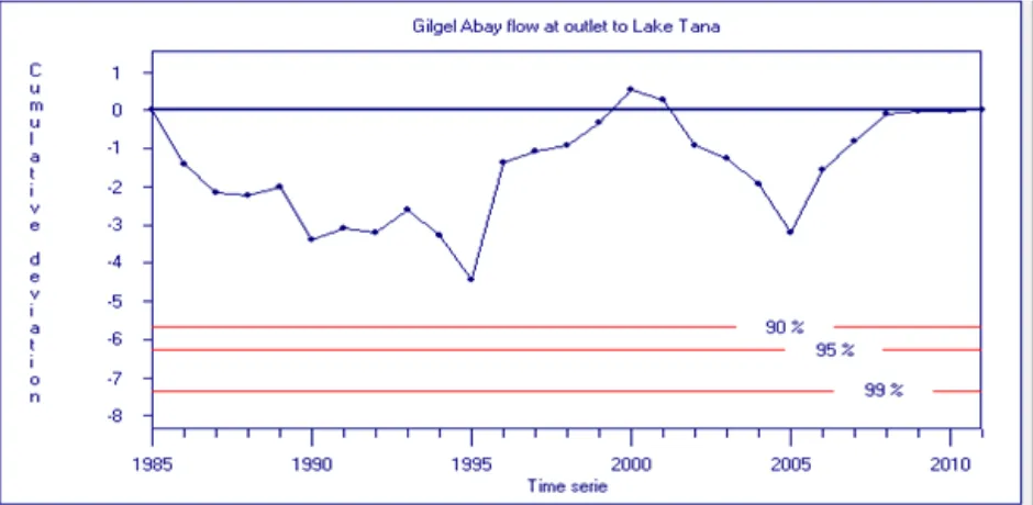
The weather data is among the most prerequisite parameter of SWAT model. This data were collected from Ethiopian National Metrological Agency. The maximum and minimum tempera-ture, precipitation, relative humidity, wind and solar radiation daily data were collected and arranged downward parallel to corresponding date of record. The SWAT weather generator parameters were estimated using pcpSTAT and Dewpoint 02. The consistency and homogeneity of hydro-meteorological data were checked using double mass curve and Rainbow respectively.
Figure 3. 3 Homogeneity test of time series flow data
3.4 Model set up
In this model set up the following steps were followed: Data preparation, watershed delineation, HRUs definition, weather write up, SWAT simulation, sensitivity analysis, calibration and validation.Data preparation: the collected DEM were projected to projected, UTM 37N. The satellite image were also classi-fied using ERDAS Imagine and saved to raster data format (UTM 37N). Following DEM data preparation, watershed de-lineation proceeded using the projected 30m by 30m DEM. After watershed delineation HRU definition using delineated watershed, land use, soil and slope class were performed us-ing multiple HRU classes usus-ing 10%/10%/10% land use, soil and slope discretization. After sub-basin discretization writing up of the prepared weather data to the model were done. SWAT simulation was also done using the HRUs and weather data inputs. Sensitivity analysis of SWAT simulation using 27 years recorded river flow and sediment was also done for identifying the most sensitive parameters. Calibration of flow and sediment simulations performed using the identified sensi-tive parameters for the periods 1995 – 2002 since the flow has no missing values during the record period. After a while, vali-dation was done for the periods 2004 – 2007. The model per-formance was evaluated using Nash Sutcliff efficiency (NSE) and coefficient of determination (R2).
𝑁𝑆𝐸 = 1 − ( 𝑆𝑖− 𝑂𝑖
2 𝑛
𝑖=1
𝑂𝑛𝑖=1 𝑖− 𝑂𝑚𝑒𝑎𝑛 2
) (9)
𝑅2= 𝑂𝑛𝑖=1 𝑖−𝑂𝑚𝑒𝑎𝑛 ∗ 𝑆𝑖− 𝑆𝑚𝑒𝑎𝑛 2 [( 𝑂𝑛𝑖=1 𝑖− 𝑂𝑚𝑒𝑎𝑛 2)0.5∗ ( 𝑆𝑛𝑖=1 𝑖− 𝑆𝑚𝑒𝑎𝑛 2)0.5]2
ISSN 2347-4289
Satellite
Image Soil DEM
Weather data Data
collection
Image Classification using ERDAS
Imagine
Reclassify Soil
Watershed Delineation
Write Input Data File
Reclassify Land use
HRU Definition
Modify Input File
Run SWAT Simulation
Sensitivity
Analysis Calibration
Re-Run SWAT Simulation
Stream flow and Sediment yield
simulation
Add Reservoirs and BMPs
Run SWAT simulation
Draw up of Conclusions
Validation Flow & sediment
Figure 3. 4 General Framework of the Methodology Used
4.
R
ESULTS ANDD
ISCUSSIONS4.1 Physical catchment characteristics
The runoff and sediment yield of a watershed is affected by the physical catchment characteristics. The physical catchment cha-racteristics of the three gauged watersheds (Upper Gilgel Abay, Koga and Kilti) and Gilgel Abay outlet at Lake Tana were deter-mined from 30m resolution Digital Elevation Model.
Table 4. 1 Physical chachment charactersitics of Gilgel Abay Watershed
No. Geographic and
physio-graphic characteristics Units
Name of the watershed
Upper
Gilgel Abay Koga Kilti
Gilgel Abay out-let @ Lake Tana
1 Catchment Area km2 1658.11 238.18 767.17 4021.8
2 Perimeter km 297.03 140.43 213.63 509.74
3 Longest flow path km 73.1 50.43 76.75 147.2
Legend
Process
Data
4 Circularity Index 52.47 82.8 59.49 64.08
5 Elongation ratio 0.93 0.35 0.41 0.75
6 Catchment shape 42.21 80.99 21.7 29.06
7 Hypsometric integral 0.28 0.23 0.31 0.23
8 Axial length of basin km 49.4 36.7 42 96.3
9 Compactness coefficient 2.04 2.57 2.36 2.26
10 Form factor, Ff 0.68 0.09 0.43 0.44
11 Drainage density 0.18 0.12 0.08 0.13
12
Slope in (%)
0-8 37.83 56.97 57.39 56.34
8.-30 50.65 37.15 41.27 38.12
> 30 11.53 6.16 1.35 5.54
13 Average slope 10.5 10.5 8.6 10.3
14 Elevation (m)
Min 1809 1839 1803 1684
Max 3528 3089 2672 3528
Mean 2292.8 2126.1
7 2070.94 2103.5
15 Cultivated % 69.97 65.66 70.58 67.48
16 Water % 2.16 9.23 3.3 5.06
17 Grassland % 2.31 3.36 22.58 11.72
18 Forest % 5.17 5.26 0.21 2.69
19 Shrub land % 20.39 16.77 3.32 13.04
The physical catchment characteristics of Gilgel Abay watershed are more or less similaras in table 4.1.
4.2 Land Use Land Cover Change Analysis
After through step by step processing and land cover detection the map showing only five (cultivated, water, grass land, shrub land and forest) classes of land use cover were created unify-ing these classes for the 1986, 2000 and 2011. Afterwards, spatial analysis of land cover has been performed to describe the overall land use cover patterns throughout the watershed. Generally major parts of cultivated land found at the middle parts of the watershed, grasslands at north and northwestern, while shrub lands at north eastern and south eastern parts of the watershed (Fig 4.1). An accuracy of image classification
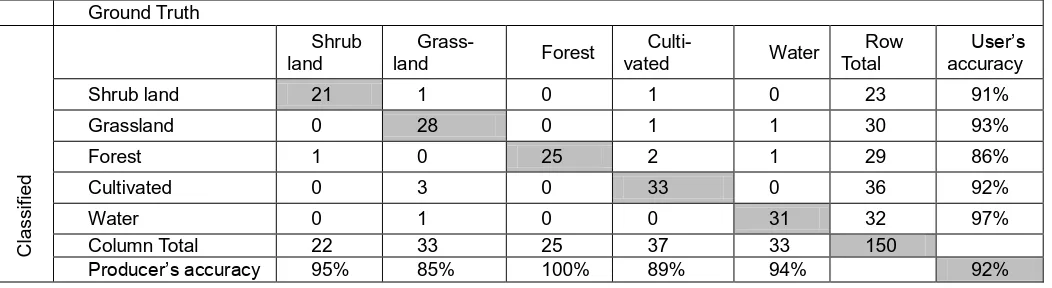
was checked with accuracy matrix using 150 randomly se-lected control points. The accuracy assessment was per-formed by using land use maps, ground truth points and Google Earth. The 2011 land use classification has showed, user’s accuracy and producer’s accuracy are greater than 85%, as well the overall accuracy of 92% (see Table 4.2). These values indicate the land sat and the methodologies used were so accurate. The Kappa coefficient also calculated, with a value of K= 0.9, which indicated the classification is al-most perfect since it is greater than 0.8.
Table 4. 2 Confusion matrix of 2011 land use classification
Ground Truth
Cl
a
ssi
fie
d
Shrub land
Grass-land Forest
Culti-vated Water
Row Total
User’s accuracy
Shrub land 21 1 0 1 0 23 91%
Grassland 0 28 0 1 1 30 93%
Forest 1 0 25 2 1 29 86%
Cultivated 0 3 0 33 0 36 92%
Water 0 1 0 0 31 32 97%
Column Total 22 33 25 37 33 150
ISSN 2347-4289
Fig.4.1 Land use land cover map of year (a) 1986, (b) 2000 and (c) 2011
The cultivated land cover shows a dramatic increase during the first period (1986 – 2000) with +24.12% than the second period (2000 – 2011) with +9.67%, on the other hand shrub lands, water and forest showed a significant decrease in the first period. On the contrary grasslands showed a higher
de-crease during the second period (-14.39%) than the first pe-riod (-10.01%) (see Table 4.2).These reveals that the changes in one land use cover resulted in a change in on the other land cover types.
Table 4. 2 Summary of land use cover change percentage of Gilgel Abay Watershed
Land cover classes
Years Land use change detection
1986 2000 2011
1986-2000
2000-2011 1986-2011
Cultivated 33.69 57.7
6 67.48 +24.12 +9.67 +33.79
Water 5.61 4.08 5.06 -1.53 -0.98 -0.55
Grassland 36.17 26.1
6 11.72 -10.01 -14.39 -24.45
Forest 4.09 2.27 2.69 -1.79 +0.39 -1.4
Shrub Land 20.45 9.73 13.04 -10.72 +3.31 -7.41
4.3 Stream flow modeling
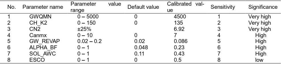
Sensitivity analysis of simulated stream flow for the watershed was performed using the daily observed flow for identifying the most sensitive parameter. 26 flow parameters were checked for sensitivity and eight sensitive parameters were identified. Calibration was done for sensitive flow parameters of SWAT
with observed average monthly stream flow data. Manual and Sequential Uncertainty Fitting program (SUFI) flow calibration was performed for the simulated results based on the sensitive parameters. This was done by simulating the flow for 9 years period including one year warm period from 1994 – 2002.
Table 4. 3 Sensitive stream flow parameters
No. Parameter name Parameter value
range Default value
Calibrated
val-ue Sensitivity Significance
1 GWQMN 0 – 5000 0 4500 1 Very high
2 CH_K2 0 – 150 0 135 2 Very high
3 CN2 ±25% 6.92 3 Very high
4 Canmx 0 – 10 0 7 4 High
5 GW_REVAP 0.02 – 0.2 0.02 0.086 5 High
6 ALPHA_BF 0 – 1 0.048 0.23 6 High
7 SOL_AWC 0 – 1 0.11 0.43 7 High
Table 4. 4 Summary of calibrated and validated performance criteria’s
Perfor-mance criteria
Calibration Validation
1986 2000 2011 1986 2000 2011
NSE 0.85 0.78 0.80 0.79 0.82 0.77
R2 0.89 0.90 0.88 0.88 0.93 0.90
RSR 0.04 0.05 0.05 0.07 0.06 0.07
Sensitivity and significance of parameters (see Table 4.4) were determined on SWAT CUP during calibration of the flow. Sen-sitivity were evaluated based on t-stat values (higher absolute value is more sensitive). Significance were also determined based on p-value (a value close to 0 is more significant). The values of NSE and R2 (see Table 4.5) of the calibrated values are greater than 0.77 which is the best predictor of the model (it shows a good correlation and agreement with the observed
mean). After calibrating manually and getting acceptable val-ues of NSE and R2 validation of simulated stream flow for 5 years period including one year warm up period from 2003 – 2007 were performed using monthly observed flows. The vali-dated results also checked using NSE and R2 having a magni-tudes greater than 0.77 and 0.88 respectively for the three different years (see Table 4.5). The RSR also shows a good estimation since the values are less than 0.7.
Fig.4.2 Monthly calibrated stream flow from 1995 – 2002 for 1986 land use
Fig. 4. 3 Monthly validated stream flow results from 2004 – 2007 for 1986 land use
ISSN 2347-4289
4.4 Evaluation of stream flow due to land use land cover change
Table 4.6 Mean annual stream flow results for the calibration and validation period
Years 1986 2000 2011 Change detection
Simulated Simulated Simulated 1986
-2000 2000-2011 1986-2011
Calibration 133.26 150.47 141.80 17.21 -8.67 8.54
Validation 134.68 137.72 140.55 3.04 2.83 5.87
The stream flow results for the different years were compared based on the validated values (see Table 4.6). Stream flows showed a higher increase in the first period (3.04m3/s) than the second period (2.83m3/s). Generally speaking stream flows has increased throughout the study period for over 25
years period with a magnitude of 5.87m3/s. These tremendous changes of stream flow were due to the land cover changes of the watershed (an increase of cultivated land trough study period).
Table 4.7 Dry and wet period season stream flow results of 1986, 2000 and 2011
Years 1986 2000 2011 Change Detection
1986 –
2000 2000 – 2011 1986 - 2011
Dry period 17.54 19.67 16.8
9 2.13 -2.78 -0.65
Wet period 260.37 272.42 277.
91 12.05 5.49 17.54
The amount of stream flow were increased by 2.13m3/s for the first period (1986 – 2000) and decreased by (-) 2.78m3/s for the second period (2000 – 2011) during the dry season. There were also changes in stream flows in the wet period with an increase of stream flow by 12.05m3/s and 5.49m3/s for the first and second periods respectively (see Table 4.7). In general, for over the twenty five years period (1985 – 2011) stream
flows has showed an increase (+17.54m3/s) during the wet season due to an increase of cultivated land by 33.79%, which implies that agricultural lands increased surface runoff (peak runoff). On the other hand, stream flows has showed a de-creasing trend for the whole study period with a magnitude of (-) 0.65m3/s, which has reflected that base flow has decreased with an intense agricultural expansion.
Table 4.8 Annual hydrology of Gilgel Abay watershed
Year Surf Q (mm)
Lat Q (mm)
GW Q (mm)
Water Yield (mm)
ET (mm)
PET (mm)
Sediment Yield (t/ha)
1986 274.6 263.24 996.03 1531.71 238.7 381.2 12.03
2000 312.22 257.69 952.46 1519.68 251.1 385.3 25.75
2011 363.91 258.84 961.43 1581.41 255.5 388.8 29.89
Effects of agriculture on water yield are of particular interest because the prior appropriation doctrine is used to allocate water rights. Therefore, understanding how agricultural activi-ties influence the quantity of water lost from agricultural lands is crucial to account for the effects of more efficient use of wa-ter as well as to decide how much wawa-ter is potentially available for appropriation by other users. Surface runoff results (see Table 4.8) signify an increase by 37.62mm and 51.69mm for the first and second periods, due to an increase of cultivated land. Surface runoff was increased with increased agricultural land because the potential for loss by runoff is increased from soil that is bare or partially bare during the cropping cycle. On the other hand, ground water flow decreased by 34.6m3/s for the whole study periods (1986 – 2011), exemplified with an increase of cultivated land which leads a decrease of infiltra-tion, as a result decreased lateral and ground water flow. Hence, this reveals that the ground water flow has showed an inverse relation with cultivated area of the watershed. The
Fig.4.4 Direct runoff and Base flow hydrograph of Gilgel Abay Watershed
4.4 Sediment yield modeling
The amount of sediment yield from Gilgel Abay watershed was simulated using spatially semi distributed SWAT model using the simulated and validated flow for the years 1986, 2000 and 2011 considering the land use change. Sediment simulated were also used for further calibration and validation in compar-ison with the observed sediment flow which was estimated by using the sediment yield versus discharge rating curve devel-oped. Sensitivity analysis of simulated sediment yield for the
watershed was performed using the monthly observed sedi-ment yield for identifying the most sensitive parameter and for further calibration of the simulation of sediment yield. During sensitivity analysis of sediment seven sediment parameters were checked for sensitivity and sensitive parameters were identified. From those parameters the first three (Spcon, Ch_cov and USLE_P) were highly sensitive and given to high priority for calibration.
Table 4.9 Sensitive sediment flow parameters
N
o. Parameter name
Parameter value range
Default value
Calibrated value
Sensitivi-ty
Signific-ance
1 Spcon 0.0001 –
0.01 0.0001 0.0001 1 High
2 Ch_cov 0 – 1 0 0.8 2 High
3 USLE_P 0 – 1 1 0.1 3 High
4 Spexp 1 – 2 1 1.75 4 Low
5 Ch_erod 0 – 1 0 0.15 5 Low
6 USLE_C 0 – 1 0.003 0.003 6 Low
The simulation of sediment yield by the model with default parameter values has reflected relatively weak agreement with the observed sediment flow hydrograph. Hence, calibration was done for sensitive sediment parameters of SWAT with observed monthly sediment flow data. Firstly the simulated sediment flow results were calibrated using SUFI. Hence after automatically calibrating and also identifying the sensitive and significant parameters manual calibration was also performed.
This was done by simulating the sediment for nine years pe-riod (1994 – 2002) for calibration and five years pepe-riod (2003 – 2007) for validation including one year warm period for each. These periods were selected since the observed flow data used for developing a rating curve did not have any missing value. The performances of the calibrated and validated simu-lations were also checked by NSE, R2 and RSR.
Table 4.10 Performance evaluation of calibrated and validated sediment yield
Perfor-mance criteria
Calibration Validation
1986 2000 2011 1986 2000 2011
NSE 0.86 0.83 0.79 0.83 0.85 0.75
R2 0. 90 0.91 0.90 0.91 0.92 0.87
RSR 0.04 0.04 0.05 0.06 0.06 0.07
ISSN 2347-4289
The calibrated and validated performance evaluation criteria values for the three different land use change are presented in (see Table 5.12). In which the NSE is greater than 0.5; it is acceptable and values are in between 0.76 and 0.86 which shows the model simulated values shows very good
agree-ment with the observed sediagree-ment load, in addition the R2 value was greater than 0.8 which indicates the simulated sediment yield is best correlated with the measured sediment yield of Gilgel Abay watershed.
Fig.4.6 comparison of measured vs. simulated sediment yield results of the calibration period (1995 - 2002) using 1986
Land use
Fig. 4.7 Comparison of observed vs. simulated sediment yield results for the validation period (2003 - 2007) using 1986 land use
Similar studies in other areas also support the findings of this study. Shimels [6] has reported that simulation of sediment for Anjeni watershed (Lake Tana sub basin) reveals good correla-tion and agreement with the observed sediment, with the val-ues of R2 (0.85) and NSE (0.81) for the calibration period.
4.5 Evaluation of sediment yield due to land use land
cover change
Table 4.11 Calibrated and validated sediment yield (t/km2/year) results of Gilgel Abay watershed
Years 1986 2000 2011 Sediment Change Detection
Simulated
Simu-lated
Simu-lated
1986 -2000 2000-2011
1986-2011
Calibration 207.49 242.15 245.07
34.66 2.92 37.58
Validation 168.41 208.42 231.19 40.01 22.77 62.78
An increase of cultivated area (1986 – 2000) by 24.12% (Table 5.1) resulted in an increase of sediment yield by 40.01t/km2 (Table 5.13), and also an increase of cultivated area (2000 – 2011) by 9.67% has increased a sediment yield by 22.77t/km2. Moreover, for over twenty five years period (1986 – 2011) there was an increase of agricultural area by 33.79% causing an increase of sediment yield by 62.78t/km2. These indicated that land use change has a significant effect on sediment yield of Gilgel Abay watershed. The land use and sediment pattern represented in (Figure 5.12), there was an increase of culti-vated land throughout the study period, and decrease of grass land and shrub land which in turn caused an increase of sedi-ment yield. This was due to cultivation caused loosening of soil layer sequentially resulting movement of a soil layer easily through water especially during peak flow periods, since
sedi-ment transport has a direct relationship with the river dis-charge. In general, (from figure 5.12) the change in cultivated land has showed a direct relationship with sediment yield; while grassland and shrub land showed an inverse relation in Gilgel Abay watershed. Spatial variability of sediment yield from Gilgel Abay watershed was identified from the validated sediment outputs for each of the sub-basins. Variability of se-dimentation rate was also identified from the potential areas. The average annual yield of sediment transport out of reach during the time step in metric tons for each sub-basin was used to generate the sediment source map. The soil erosion or sedimentation levels in the basin were classified as low (0 – 20 t/ha/yr), moderate (20 – 50t/ha/yr), high (50 – 150t/ha/yr) and very high (>150t/ha/yr).
Fig.4.8 Spatial distribution of sediment transported with water out of reach during time step (t/ha/yr) in Gilgel Abay watershed
According to the sediment results; of the sub-basins in Gilgel Abay watershed (Fig4.8), basins 30 and 31 are high, sub-basins 26, 29, 25 and 10 were moderate potential source area for sediment, and on the other hand sub-basin 23, 5, 3 and 1 were very low potential source area for sediment having less than 2.5t/ha/yr. Shimels [6] also showed that upstream parts
ISSN 2347-4289
of soil erosion. On the other hand very low rate of soil erosion (sediment movement) was occurred during dry seasons which
had very small amount of flow.
Fig.4.9 Temporal Variability of sediment in Gilgel Abay Watershed
The amount of sediment that flows to Lake Tana estimated using the recent (2011) land use was 1,018,000 tons per year. Moreover the implementation of proposed Gilgel Abay reser-voir reduces the amount of sediment that flows to Lake Tana by 12.36% with an amount of 892,217 tons per year. There were 524,488 tons annual sediment load to proposed Gilgel Abay reservoir and 104,801ton/year load to Koga reservoir. Generally, sediment transport in Gilgel Abay watershed is very high in turn sediment load to lake were so large without any reservoirs upstream. Therefore, the implementation of the pro-posed Gilgel Abay reservoir plays a great role in decreasing the amount of sediment load to Lake Tana.
4.6 Best Sediment management scenario development
and analysis
According to spatial variability of sediment source and sedi-ment rate /erosion level identified in section 4.5 and 4.6 the BMP scenarios were developed. Identified and selected sce-narios were also applied to SWAT model for simulating and identifying the effects of these best management practices on sediment yield of the watershed. During this study three differ-ent scenarios were developed and compared according to their effectiveness of soil conservation or sediment reduction.
Table 4.12 Summary of Sediment management scenarios
Scena-rios Description
SWAT parameter used Parameter name (input
file) Calibration value Modified value
S0 Base case
S1 Filter strip FILTERW 0m 1m
S2 Stone bund
SLSUBBSN 0-30% 60 & 24m 10m
>30% 9.14m 9m
USLE_P 0.15 0.1
S3 Reforestation 5% of Cultivated, grass land and shrub land
In the Base case scenario (S0) the watershed existing condi-tions were considered. The 2011satellite image land use were used as existing conditions and the sediment were also simu-lated, calibrate and validated for using it as a baseline for the other two scenarios’ development and comparison. In scenario 1 filter strips were placed on all agricultural HRUs which are a combination of cultivated land, all soil types and slope classes. The effect of the filter strip is to filter the runoff and trap the sediment in a given plot [9]. Appropriate model parameter for representation of the effect of filter strips is width of filter strip (FILTERW). FILTERW value of 1m spacing was checked to simulate the impact of filter strips on sediment trapping. This value was modified by editing the HRU (.hru) input table. The filter width value was assigned based on local research expe-rience in the Ethiopian highlands [10] and [11]. Stone bunds were designed as scenario S2, by changing the parameter values of SLSUBBSN and USLE-P files on SWAT parameters database table. SLSUBBSN and USLE_P values were
mod-ified on (.hru) and (.mgt) input tables respectively. The practice of using stone bunds has a function to reduce overland flow, sheet erosion and reduces slope length [9]. In Scenario S3, reforestation of 5% of cultivated, grass land and shrub lands from the recent (2011) land use cover were considered and the amount of sediment reduction throughout the watershed were estimated and compared with the other above two sce-narios. Since similar studies on other areas has also assumed that 8% change of cropland, mixed forest and shrub land to evergreen forest [11].
4.7 Evaluation of Best Management Practices
from those BMPs; reforestation was the best effective method of sediment reduction in Gilgel Abay watershed. The results of sediment yield using the different BMPs as well their efficiency
of sediment reduction are presented in Table 4.13.
Table 4.13 Summary results of BMPs efficiency
Scenario
No. BMPs
Performance of Calibra-tion
Performance of Validation
Sediment yield
(t/km2/yr) % reduction
R2 NSE R2 NSE
S0 Baseline 0.90 0.79 0.87 0.75 231.19
S1 Filter strip 0.91 0.84 0.88 0.80 174.02 24.73
S2 Stone/soil bund 0.91 0.88 0.88 0.80 181.82 21.36
S3 Reforestation 0.90 0.73 0.88 0.78 147.55 36.18
Those BMPs also have its own role on reduction of sedimenta-tion of the proposed Gilgel Abay and Koga funcsedimenta-tional reservoir. As a result the sustainability of those two reservoirs will be increased. Hence the implementation and encouragement of those BMPs is very crucial for Gilgel Abay watershed devel-opment programs. Sedimentation of proposed Gilgel Abay reservoir will also decreased by 40% with implementing S3 (reforestation) scenario.
5.
C
ONCLUSIONS ANDR
ECOMMENDATIONS5.1 Conclusions
During this study the impact of land use cover changes on Gilgel Abay watershed for over 25 years period were detected using Landsat satellite images from USGS earth explorer and GLOVIS. The classified land use covers performed on ERDAS Imagine 2014 were integrated with other GIS data as a result stream flow and sediment simulations were done using SWAT model. From this study it can be concluded that Gilgel Abay watershed has experienced a significant change in land use land cover over the past 25 years. It can be recognized that deforestation and increase of agricultural lands was exhibited by rapid increase of human population which changes the whole Gilgel Abay watershed in general and some sub-watersheds in particular. Grasslands and shrub lands were significantly changed to cultivated lands showing an identical trend for the two consecutive periods (1986 – 2000 and 2000 – 2011). There were also a decrease of forests for the first period and while it resulted slight increase during the second period due to reforestation policy implemented on Ethiopian millennium. The results revealed, showed the magnitudes of the cultivated land were increased by 24% from 1986 – 2000 and by 9.67% from 2000 to 2011, the grassland were de-creased by 10% and 14.39% from 1986 to 200 and 2000 to 2011 respectively. The changes in land use has resulted changes in stream flow, in which the expansion of agriculture results an increase of surface runoff, on the other hand, lateral and ground water flow decreases with an expansion of agricul-ture. The significant changes of stream were occurred in wet periods than dry periods. The water yield was also increased with an increase of cultivated land. The evaluated base flow of Gilgel Abay watershed was 31% of total runoff of simulated flow. Sediment yield transported through rivers out of the wa-tershed simulated using SWAT, and calibrated manually and automatically using SWAT CUP. Sediment yield was depen-dent of land use cover changes; hence in Gilgel Abay wa-tershed which has showed a significant land use cover change implied a change to the amount of sediment yield flows out of
the watershed. As a result the sediment yield was increased from year to year during the 25 years period due to a conver-sion of shrub lands and grasslands to cultivation. Over 25 years period (1986 – 2011) an increase of cultivated land by 33.79% resulted in an increase of sediment yield by 62.78t/km2. Generally sediment yield has showed a direct rela-tionship with cultivated land as a result the sediment increased from year to year. The spatial and temporal variability of sedi-ment source areas was identified and mapped using Arc GIS. As a result sub watersheds of 29, 30 and 31 were identified as more potential sediment source areas (highly erodible). Those sub watersheds indicated that, it requires attention for best management practices in the watershed. The temporal varia-bility of sediment yield at the outlet was done using the cali-brated sediment yield; hence the highest amount of sediments was occurred during wet months.BMPs were designed and their sediment reduction efficiencies on Gilgel Abay watershed had been compared between them. As the result reforestation (5% of cultivated, grass land and shrub lands) was more effec-tive means of watershed management in terms of sediment reduction. Filter strips has also showed 24.73%, reforestation 36.18% and stone bunds 21.36% sediment yield reduction efficiencies.
6.
A
CKNOWLEDGEMENTISSN 2347-4289
Ademe, Girum Getachew, Chekole Tamalew and Getachew Tsigie) for their appreciation, supports and encouragements.
7.
R
EFERENCES[1] Hari Krishna B*, R. Sai kumar, O. Sampath and T. Na-gendher. (2014). A Review- Impact of land use land cover change and best management practices in a wa-tershed by using swat model. International Journal of Pure & Applied Bioscience.
[2] CSA. (2008). Summary and statistical report of the 2007 population and Housing census: population size by age and sex. Addis Ababa: Federal Democratic Republic of Ethiopia Population Census Commission.
[3] SMEC. (2007). Hydrological Study of Tana Beles Sub-Basins, part I. Sub-Basins Ground water investigation report. SMEC International Pvt Ltd.
[4] Rientjes, T. H. M., Haile, A. T., Kebede E., Mannaerts, C. M. M., Habib E. and Steenhuis, T. S., (2011). Changes in land cover, rainfall and stream flow in Upper Gilgel Abbay catchment, Blue Nile basin, Ethiopia. Hydrol. Earth Syst. Sci., 15, 1979–1989, 2011. www.hydrol-earth-syst-sci.net/15/1979/2011/ doi:10.5194/hess-15-1979-2011
[5] Green, W.H. and Ampt G.A., (1911). Studies on soil physics, 1. The flow of air and water through soils. Journal of Agricultural Sciences , 4: 11-24.
[6] Shimelis, G., (2008). Hydrological and sediment yield modeling in Lake Tana basin, Blue Nile Ethiopia. Royal Institute of Technology (KTH), SE-100 44 STOCK-HOLM, Sweden TRITA-LWR.LIC 2042, ISSN 1650-8629, ISRN KTH/LWR/LIC 2042-SE, ISBN 978-91-7415-026-1.
[7] Shimelis, G. S., Ragahavan, S. and Bijan, D., (2008). Hydrological Modelling in the Lake Tana Basin, Ethiopia Using SWAT Model. The Open Hydrology Journal, 2, 49-62.
[8] Shimelis, G. S., Ragahavan, S., Bijan, D. and Assefa M. M., (2009). Spatial delineation of soil erosion vulnerabili-ty in the Lake Tana Basin, Ethiopia. 1-3. Hydrological Processes. DOI: 10.1002/hyp.7476.
[9] Bracmort, K., Arabi, M., Frankenberger, J., Engel, B., and Arnold, J., (2006). Modeling long-term water quality impact of structural BMPs, T. ASABE, 49, 367–374.
[10] Hurni, H., (1985). Erosion productivity conservation sys-tems in Ethiopia, in: Proceedings of the 4th International Conference on Soil Conservation, Maracay, Venezuela, 654–674.
[11] Betrie, G.D., Mohamed, Y.A., Griensven, A.van, and Srinivasan, R., (2011). Sediment management model-ling in the Blue Nile Basin using SWAT model. Hydrol. Earth Syst. Sci., 15, 807–818, 2011 www.hydrol-earth-syst-sci.net/15/807/2011/ doi:10.5194/hess-15-807-2011.
[12] Arnold, J.G., Srinivasan, R., Muttiah, R.R., Williams, J.R., (1998). Large Area Hydrologic Modeling and As-sessment Part I: Model Development. Journal of the American Water Resources Association, 34(1): 73-89.
[13] Green, W.H. and Ampt G.A., (1911). Studies on soil physics, 1. The flow of air and water through soils. Jour-nal of Agricultural Sciences , 4: 11-24.