International Journal of Industrial Electronics, Control and Optimization .
© 2019 IECO…. Vol. 2, No. 1, pp. 25-38, Jan (2019)A New Sliding Mode-Based Power Sharing Control Method for
Multiple Energy Sources in the Microgrid under Different
Conditions
Reza Sedaghati
†, and Mahmoud Reza Shakarami
*A single-phase distributed generation (DG) sources embedded in three-phase microgrids develop with a fast-paced trend, it is important to make use of suitable power sharing strategies among multiple DGs and utilizing the power generation of these units to the full capacity. This paper presents an innovative sliding mode-based power control strategy for microgrids. The multi-bus microgrid consists of three-phase DG units that are two photovoltaic (PV) array, and three single-phase DG units including PV, battery and fuel cell (FC). The dynamic modeling of all DGs is based on voltage source inverter (VSI). One of the three-phase DGs is responsible for frequency and voltage control, and the other one for current control. The single-phase DGs are controlled based on the three-phase DGs. Finally, the voltage and power control operations are implemented in a per-unit system. The proposed control strategy has a fast response and the ability to trace a reference signal with a low steady-state error compared with the PI controller; moreover, it provides the accurate active and reactive power sharing among energy units under various faults and loading conditions along with robustness against the microgrid parameters. Additionally, the ability to maintain the dc-link voltage and frequency constant is another feature of this controller.
Article Info
Keywords:
Power Sharing Control, Sliding Mode, Distributed Generations, Microgrid.
Article History:
Received 2018-03-09
Accepted 2018-08-15
N
OMENCLATUREIph Photocurrent
Isat Module reverse saturation current Isso Short current
Q Electron charge K Boltzman constant A Ideality factor
T Surface temperature of PV cell Rp Parallel resistance of a PV cell Rs Series resistance of a PV cell ki Short circuit temperature coefficient Tr Reference temperature
Irr Reverse saturation current at Tr Egap Energy of the band gap for silicon np Number of cells in parallel ns Number of cells in series S Solar radiation level Voc Rated open circuit voltage E0 Free reaction voltage F Faraday’s constant
N0 Number of series connected cells r Ohmic resistance
R Universal gas constant Ifc FC output current Q Battery capacity B Exponential capacity
K Polarization voltage
V0 Open circuit voltage of the battery Rb Internal resistance of the battery ib Battery charging current u Input signal of controller Ui VSI output voltage Vf Capacitor voltage ILf Inductive current
ICf Output current of the capacitor Io Output current of the filter Vdc DC link voltage
x System state vector
λ Positive number
η Positive number
s
η Constant positive number
max
I Maximum producible current of inverter-based DG unit
load
I Load current
I.
I
NTRODUCTIONRapid growth of demand for fossil fuels such as coal, petroleum, and natural gas moves the world towards a general tendency for the power generation through developing Renewable Energy Source (RES) units [1-3]. The need for improving the reliability and power support in electrical grid along with a high demand for energy are becoming a major challenge encountered by modern power networks. In the last decade, the growing number of consumers in the demand
*
Corresponding Author: [email protected] Tel: +98-663-3120097, Fax: +98-663-3120086.
†*
Department of Electrical and Power Engineering, Faculty of Engineering, Lorestan University, Khorramabad, Iran.
management system needs a wide range of infrastructures such as large power plants and distributed generation (DG) units [4].
Microgrid is a new concept consisting of RES units, energy storage (ES) devices, DG units and loads. A microgrid is basically an active distribution grid, which can be operated in two operating modes, i.e., grid-connected and islanded modes [5]. In the grid-connected mode of operation, the microgrid is connected to the main grid at the point of common coupling (PCC), and the important task of each DG is to produce pre-determined values of real and reactive powers [6]. In the islanded mode of operation, the microgrid is separated from the main grid, and in order to maintain the stability of frequency, the power exchange among energy units must be balanced [7].
Renewable energy source units, such as wind, PV, etc., are highly unpredictable, intermittent in nature and sensitive to weather conditions. These units cannot provide the constant power conditions and guarantee the load demand continuously. Therefore, these units require integration with the ES devices, and this combination is called a hybrid power system (HPS) [8]. For reliable operation of a microgrid, the balance of power between production and consumption should be maintained instantaneously. Therefore, the power sharing is a challenge in the presence of RES units, ES devices and load demands. Many works have been dedicated to power management in the multiple DGs-based microgrids for various operating modes.
The performance of energy resources including SC, FC, and PV for islanded microgrids has been studied in [9] under unbalanced and nonlinear loading; however, the proposed method is not very effective for power control among DG units. Also, the DG units and loads are all three-phase, and the single phase DG units and single-phase loads not intended. In order to adjust the dc voltage, a fuzzy controller based on flatness feature is expressed in [10] for an autonomous system containing of PV, FC, and SC. The proposed control strategy is only for the three-phase DG units in the microgrid, and cannot be implemented for single-phase DG units.Also, the problems of active power sharing have been studied, but the reactive power sharing has not been evaluated.In [11], a centralized coordination control method is applied to proper power transfer between AC and DC buses. Although centralized control approaches have a higher controllability and predictability than decentralized ones, their response speed and reliability are much less. Therefore, the inappropriate performance of controller can lead to a complete network failure.
Droop method is a known approach for power management control in microgrids that include several energy generation units. In [12], a reactive power sharing approach based on hierarchical droop control method is developed. Although the droop controller does not require any communication link
between the DG units, this method can lead to system instability in conditions that the droop characteristics has small slopes [13]. Also, in this method to suitable power sharing among the DGs in the microgrid, the voltage and frequency deviate from their nominal value. A two-level structure based on multi-agent control is considered in [14] for the energy management of a microgrid that includes multiple DG units. In [15], a grid-connected microgrid is considered that includes wind, gas engine system, PV arrays, and battery storage energy unit. This microgrid supplies the power needed for electric loads. The energy management method creates a precise balance between the consumed and produced powers. In [16], an AC grid-connected microgrid is proposed that contains PV units as main sources and the battery banks as energy storage units. All energy resources are connected to the AC grid by the interfacing inverters. A central control method for energy management is designed that controls the real and reactive power of units. To real power sharing among distributed resource units in [17] an autonomous control method has been raised, in which reactive power sharing is not evaluated. In [18], a PV array, a diesel generator, and a battery bank in the microgrid are connected to the AC gird in order to support the loads within the microgrid. Moreover, in this structure, another battery bank and PV array are employed to supply power for communication and monitoring systems. Residential service is provided by three parallel battery units using droop control approach in which network frequency is applied as communication signal. Moreover, some other researches have considered the power management based on: H-infinite [19], fuzzy logic [20], network [21], Model Predictive [22], and multi-agent [23] strategies.
In particular, faults in general and short-circuit currents are the very severe operating conditions in distribution networks [24]. Different researches are discussed under the concept of transient stability subsequent to the fault event condition [25-26]. In [27], a fault analysis approach for inverter-interfaced DG units is expressed. This approach is used to estimate the initial high current that an inverter interfaced DG unit under voltage control strategy can inject during the first cycle of fault. In [28] considers a direct building method for energy sources-based microgrid during fault analysis. A novel scheme is attempted in [29] to improve microgrid performance under fault conditions with battery units. However, this scheme has some limitations for a sustainable operation; that is, the remaining storage energy of battery unit should be zero.
International Journal of Industrial Electronics, Control and Optimization .
© 2019 IECO 27 dependence on system parameters.Sliding Mode Control (SMC) is a robust control method for nonlinear systems with variable-structure that does not require a lot of computational operations, and has little sensitivity to variations in system parameters. Additionally, the SMC approach applies a special version of on-off control, which its functional behavior provides relative immunity against external disturbances [30]. In [31], a SMC-based direct approach for the voltage control of microgrid based on converters is proposed in which the output controller due to chattering phenomena is very weak. In [32], an SMC method is proposed that contains an inner SMC for the voltage and current stability, and an outer voltage control loop to reduce the tracking error; however, application of the control method only for a single-phase inverter is implemented.
It should be noted that the aforementioned works have been often limited to the microgrid based on three-phase DGs, and few researches have been done on power sharing and control in the microgrid based on single-phase DGs. In addition, due to the aforementioned issues and some disadvantages of the SMC approach, this study presents a new reactive and real power sharing control method for multiple DG units based multi-bus microgrid. The battery, FC, and photovoltaic array are considered as the three-phase and single-phase inverter-based DGs in the microgrid. The proposed power sharing control approach is based on a new SMC, which can regulate the voltage, frequency and power components of the DGs based on inverter. In addition, the proposed approach is robust, has a high-speed response compared to the conventional PI controller and is stable under different faults and loading conditions.
II.
M
ICROGRIDS
TRUCTUREThe single-line diagram of the multi-bus microgrid is illustrated in Fig. 1. The microgrid contains two DG units based on voltage source inverter (VSI), which include three-phase PV arrays (DG1 and DG2). Moreover, three DG units based on VSI that consist of single-phase energy storage battery unit (DG3), fuel cell unit (DG4) and PV unit (DG5) are included. The single-phase DG units are connected to phase-A, B, and C. The DG units provide almost a constant DC-bus voltage for the inverter. The loads are modeled as constant-impedance, where L3, L4, and L5 are single-phase loads, while L1 and L2 are three-phase loads. The single-phase loads are in the vicinity of the single-phase DG units. The loads are fed through three radial feeders, and the DGs supply feeders. Under a normal state, the entire microgrid system is in a balanced state. All information about the microgrid parameters and DG units are given in Tables I, II, and III.
s
Z
s
T
UpstreamNetwork
1 P
Z ZP2 ZP3 ZP4
1
L L3 L4
PV PV Bat FC
1
DG DG2 DG3 DG4 2
L
Three Phase DGs & Loads
5 P
Z
5
L PV
5
DG
{
Single Phase DGs & Loads
Fig. 1. Single-line schematic diagram of the grid-connected microgrid.
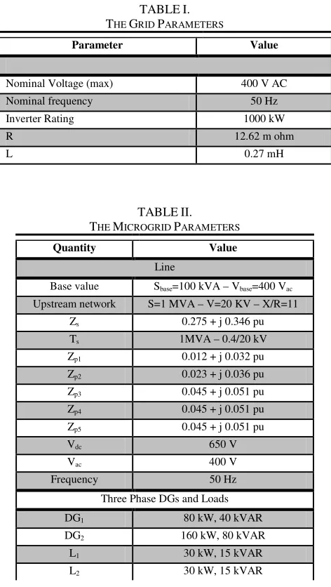
TABLEI.
THE GRID PARAMETERS
Parameter Value
Nominal Voltage (max) 400 V AC
Nominal frequency 50 Hz
Inverter Rating 1000 kW
R 12.62 m ohm
L 0.27 mH
TABLEII.
THE MICROGRID PARAMETERS
Quantity Value
Line
Base value Sbase=100 kVA – Vbase=400 Vac
Upstream network S=1 MVA – V=20 KV – X/R=11
Zs 0.275 + j 0.346 pu
Ts 1MVA – 0.4/20 kV
Zp1 0.012 + j 0.032 pu
Zp2 0.023 + j 0.036 pu
Zp3 0.045 + j 0.051 pu
Zp4 0.045 + j 0.051 pu
Zp5 0.045 + j 0.051 pu
Vdc 650 V
Vac 400 V
Frequency 50 Hz
Three Phase DGs and Loads
DG1 80 kW, 40 kVAR
DG2 160 kW, 80 kVAR
L1 30 kW, 15 kVAR
Single Phase DGs
DG3 Battery @ A 60 kVA, cos φ=0.9
DG4 FC @ B 60 kVA, cos φ=0.9
DG5 PV @ C 80 kVA, cos φ=0.9
Single Phase Loads (Symmetric)
L3 20 kW, 10 kVAR
L4 20 kW, 10 kVAR
L5 20 kW, 10 kVAR
TABLEIII.
THE DGUNITS PARAMETERS
Quantity Value
parameters of PV array
Number of Series-Connected Modules per String 12
Number of Parallel Strings 80
Number of Cells per Module 96
Open Circuit Voltage 642.2 V
Short-Circuit Current 5.96 A
Diode Quality Factor 1.25
Parallel Resistance 1723 ohm
Series Resistance 0.0101 ohm
Forward Voltage of Diode 0.8 V
parameters of Battery unit
Nominal Voltage 48 V
Rated Capacity 86 Ah
Initial State-Of-Charge 64 %
Internal Resistance 0.012 ohm
Full Charged Voltage 55.87 V
Number of Series-Connected Modules per String 14
Number of Parallel Strings 52
parameters of SOFC unit
Voltage at 0 Amper 52.2 V
Voltage at 1 Amper 52.46 V
Nominal Operating Point (Irated, Vrated) (250 A,41.15 V)
Number of Cells 125
Number of Parallel Strings 26
Operating Temperature 318 K
Nominal Air Flow Rate 732 lmp
Nominal Supply Pressure of Fuel 1.16 Bar Nominal Supply Pressure of Air 1 Bar
SOFC Resistance 0.024 ohm
SOFC Response Time 1 second
Nominal Composition of Fuel (H2, O2, H2O) (95.95, 21, 1)
III.
M
ATHEMATICALM
ODELING ANDD
ESCRIPTIONOF
E
NERGYS
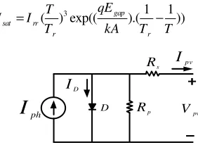
OURCESA. Modeling of a PV unit with MPPT Algorithm
Fig. 2 shows the circuit model of a PV unit. The current output of the PV unit is obtained by dynamic equations as follows [33]:
) 1 (
exp(( )( pv )) 1
pv p ph p sat pv s
s
V q
I n I n I I R
AkT n = − × + − ) 2 ( ( ( )). 1000
ph sso i r
S I = I +k T −T
) 3 (
3 1 1
( ) exp(( gap).( ))
sat rr
r r
qE T
I I
T kA T T
= − ph
I
D I pv ID Rp s R
pv
V
Fig. 2. Equivalent circuit model of a PV array.
Although a photovoltaic array has many benefits in energy production, its efficiency depends on some environmental effects such as temperature, radiation level, shading and the amount of dirt, which is very low. Therefore, the maximum power (MP) transmission of the PV array is essential. In this paper, to reach the available MP point tracking, the incremental conductance (IC) [34] approach is employed, in which the subject of tracking MP is resolved under rapidly changing atmospheric condition. The IC approach is based on the fact that the slope of the PV array power is zero at the MP point, positive on the left of the MP point and negative on the right.
B. Modeling of a Solid Oxide Fuel Cell (SOFC) Unit
The considered dynamic model of the SOFC is based on the relationship between the terminal voltage of FC (Vfc) and the partial pressures of water, hydrogen and oxygen (PH2O, PH2 and PO2), respectively [35]. The output voltage of SOFC is determined in accordance with the Nernst’s equation and Ohm’s law as follows:
) 4 ( 2 2 2 0/5 0 0 .
(ln( )) .
2 H O fc fc H O P P RT
V N E r I
F P
= + −
C. Modeling of a Battery Unit
In order to show the battery energy storage model, two significant parameters are considered that consist of the terminal voltage (Vb) and the state of charge (SOC) as follows [36]:
) 5 (
0 . .exp( )
b b b b
b
Q
V V R i K A B i dt
Q i dt
= + − +
+
∫
∫
) 6 (
100(1 i dtb )
S OC
Q
= +
∫
IV.
D
YNAMICM
ODELING OFI
NVERTERB
ASEDM
ICROGRIDIn the studied microgrid in Figure 1, DG1 and DG2 are three-phase DG units based on the voltage source inverter (VSI) in the microgrid, which DG٢ as a frequency and voltage control resource is responsible for adjusting the
International Journal of Industrial Electronics, Control and Optimization .
© 2019 IECO 29 voltage of the microgrid in accordance with the voltagereference signal. Additionally, DG١ has considered as a power control resource, which operates based on the current reference signal and provides a certain amount of load power until its maximum capacity. It is assumed that the load currents are measurable. In order to control the single-phase DG units based on VSI (DG3, DG4 and DG5 resources), their current and voltage references are received from its corresponding phase of the current and voltage control units (DG2 and DG1 sources), respectively. After determining the power and voltage references, the single-phase controllers in the per-unit system perform the power control by using the proposed control method based on the new SMC.
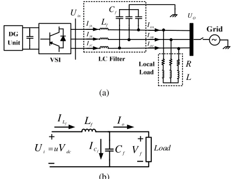
A three-phase inverter-based DG unit with an output LC filter is shown in Figure 3(a). For simplicity, at first, the modeling of single-phase inverter is described, and then, the equations are developed for the three-phase inverters. It is considered that the structures of all phases in three-phase inverters are similar to each other. Figure 3(b) illustrates the model of a single-phase inverter [37].
f
L UO
f C in U L R OA I OB I OC I fA I fB I fC I (a) = i u dc U V f L f C f L I o I f C I f V Load (b)
Fig. 3. (a)- Configuration of three-phase inverter system with LC filter, and (b)- the single-phase equivalent circuit of inverter.
According to Fig. 3(b), the state space equations of the single-phase inverter can be written as:
) 7 (
f L
f f i dc
dI
L V U uV
dt + = =
) 8 (
0,
f f f
f
L C C f
dV I I I I C
dt
= + =
According to (7) and (8), we have:
) 9 ( 0 1 0 0 1 0 0 f f
f f f
f dc L L f f I V C V
d C u V I I dt L L − = + + −
where state variables are capacitor voltage and inductive current.
V.
T
HEP
ROPOSEDC
ONTROLS
TRATEGY FORDG
U
NITSB
ASED ONS
LIDINGM
ODEA. Sliding Mode Control Method
Sliding mode control (SMC) is a variable structure approach, in which the controller output is the system state variables [38]. Some of the important benefits of SMC are its robust stability against load, suitable dynamic response and easy implementation. The nth order model of the system is considered by the SMC, which can be expressed as:
) 10 ( ( )n ( ) ( ) ( )
x =f x +g x u+δ x
where
δ
( )
x
is the system disturbance and can beattributed to noises and/or load variation. In order to track a reference signal in SMC strategy, a sliding surface based on the system order should be defined. In this paper, state space equation of the system is considered to be of first or second order; thus, these kinds of sliding surfaces are defined as follows.
The sliding surface (S) of the first-order system based on
the error between reference signal (xref) and output (x) can be defined as:
) 11 (
ref
S =x −x
The purpose of the control strategy is to minimize the tracking error from reference signal. Therefore, the derivative of Smust be equal to zero:
) 12 (
1
0 ( ) ( ) ( ) 0
( )[ ( ) ( ) ]
ref ref
ref eq
S x x f x g x u x x u g x f x x x
δ δ • • • • • − = → − = + + − = → = − − +
If the error between reference signal and output is defined as x%= −x xref , then the sliding surface of the second-order system can be expressed as:
) 13 (
S =x•%+λx%
If S
•
is equal to zero, we have:
) 14 (
1
0 0
( , ) ( ) ( ) 0
( )[ ( , ) ( ) ]
ref
ref
eq ref
S x x x
f x x g x u x x x
u g x f x x x x x
λ δ λ δ λ • − = → − + = → + + − + = → = − + − − & && && %
& & && %
& & && %
In order to have a robust controller against external disturbances, the control law can be obtained as:
) 15 (
( ) eq
u =u −ksign S
In order to verify stability of the defined control law, a Lyapunov function (
V x
( )
) must be considered; if the timederivative of the Lyapunov function (V•(x)
) is definitely
) 16 ( 2 1 ( ) ( ) 2
V x = S → V x• =S S• p−ηS
B. Voltage-Frequency Controller
In this stage, for the voltage and frequency control, the voltage error can be written as:
) 17 ( 1 f ref
x =V −V
) 18 ( 2 1 1 ( ) f
f ref C ref
f
d d d
x x V V I V
dt dt C dt
= = − = −
The reference signal (Vref) can be expressed as:
) 19 ( sin( )
ref m
V =V ωt
Based on (17) and (18), equation (9) can be rewritten as:
) 20 ( 1 1 2 2 0 0 1 0 1
0 dc ( )
f f f f
x x
d
u V
x x D t dt
L C L C
= + + −
2 0 2 1 1
( ) ref ref
f f f
dI d
D t V V
C dt L C dt
= − − −
According to (21), the state-space equation of the system is of second order; therefore, the switching surface can be obtained as:
) 21 (
1 2, 0
S =λ×x +x λ f
Moreover, the sliding surface is obtained and set to zero so that the equivalent control is determined as:
) 22 (
2 1
1
0 f f [ ( )]
eq
dc f f
L C d
S u x x D t
dt = → = V −λ +L C −
As a result, the control law can be expressed as:
) 23 (
( )
eq V
u=u −K ×sign S
In order to assess the stability, the Lyapunov function can be defined as:
) 24 ( 2 1 2
V = S
the stability can be achieved if V 0
•
p , therefore, we have:
) 25 ( f f V dc L C
V S S K
V
η η
• •
= − →
in which η is the term of maximum disturbance of
D t
( )
and D t( )≤η.
C. Current Controller
In this stage, the current control strategy will be designed. According to the output current, equations (8) and (9), the state space of system is first order. Therefore, the system model can be written as:
) 26 ( 0 1 f dc f C f f V d d
I V u I
dt = −L + L −d t
furthermore, the sliding surface can be expressed as:
) 27 ( 0 ref
S=I −I
then, by setting Sequal to zero, the equivalent control can
be obtained as:
) 28 (
1
0 ( )
f f
eq f C ref
dc f
L
d d d
S u V I I
dt = → =V L +dt +dt
As a result, the current control law can be expressed as:
) 29 (
( )
eq s
u=u −K ×sign S
To keep stability, the Lyapunov function proposed in (24) is employed to determine the boundaries of the parameter
s K ) 30 ( f s s dc L K V
η
fThe DG unit has constraints for generation power; therefore, the reference current signal magnitude must be limited [39]. Equation (31) indicates the limitation on the reference current. It is necessary to mention that a percentage of the load current is dedicated to the reference current signal. The considered formulation can be expressed as:
) 31 (
max
load ref load
if I ≤I → then I =I
max max load load ref load I if I I then I I
I
→ =
f
International Journal of Industrial Electronics, Control and Optimization .
© 2018 IECO…31dc V
f
L
f C
dc
V
f L
f C
L5
L4
L3
DG3
DG4 DG5
L1
Phase B
Phase C
PWM
Voltage Control ILf
V
refICf
1
IO
1
IO
PWM
Power Control
ILf
Iref
ICf 2
IO
2
IO
L2
PV
FC Phase A
Battery
DG2
DG1
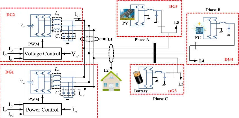
Fig. 4. The studied microgrid containing of three-phase and single-phase DG units with the control strategy.
VI.
S
IMULATIONR
ESULTSTo demonstrate the appropriateness of the proposed power sharing and control strategy, the performance of islanded AC microgrid has been studied in Matlab/Simulink environment under various scenarios, including balanced loading conditions and different types of faults.
A. Operation under Balanced Load Conditions
In this case study, until t=1 s, the loads L2 to L5 are located in the microgrid. The total reactive and active demands of all these loads are 45 kVAR and 90 kW, respectively. Power management between the three-phase and single-phase has been conducted balancedly, so that the share of each of single-phase DG units is equal to 10 kVAR and 20 kW. At t=1 s, the three-phase load L1 with a demand of 20 kVAR and 40 kW is added to the microgrid, and as expected, the power sharing is performed according to the generation capacity of the three-phase DG units. At t=2 s, the three-phase load L1 is removed from the microgrid and it goes to normal conditions.
During the time interval t=1 s to t=2 s that L1 is in the microgrid, the share of power production of each of single-phase DG units is enhanced to 5 kW. Each of the single-phase DG units including DG3, DG4 and DG5 feeds its local load, independently. Therefore, it is expected that all consumption of single-phase loads is supplied by these units. In figures 5, 6 and 7 the active and reactive powers of single-phase DG units such as: battery, FC and PV are illustrated, respectively. It is noteworthy that the response of the proposed control method is faster than the conventional PI controller. Also, the steady-state error is reduced.
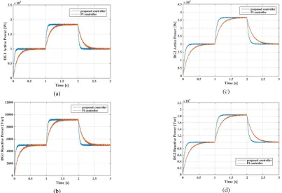
Fig. 8 demonstrates the generated active and reactive power of the three-phase DG sources (DG1 and DG2). As it is seen, the proposed control method has a suitable performance compared to the PI controller.
(a) (b)
(a) (b)
Fig. 6. Dynamic response and comparison between proposed an PI controller of single-phase DGs in balanced load conditions: (a)-
Active power output of FC unit (DG4), (b)- Reactive power output of FC unit (DG4).
(a) (b)
Fig. 7. Dynamic response and comparison between proposed an PI controller of single-phase DGs in balanced load conditions: (a)-
Active power output of PV unit (DG5), (b)- Reactive power output of PV unit (DG5).
(a) (c)
(b) (d)
Fig. 8. Dynamic response and comparison between proposed and PI controller of three-phase DGs in balanced load conditions: (a)-
International Journal of Industrial Electronics, Control and Optimization .
© 2018 IECO…33B. Operation under Types of Faults
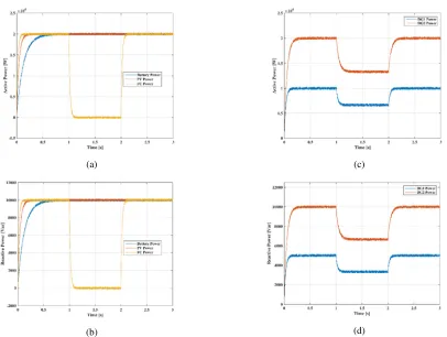
Single Line-to-Ground (L-G) Short Circuit Fault It is assumed that the L-G fault occurs at the point of common coupling (PCC) during the time interval t=1 s to t=2 s. An L-G fault occurs in one of the phases and no change can be seen in other phases. Therefore, it is expected that output power of single-phase photovoltaic and battery units do not
experience much changes. Fig. 9 shows the active and reactive powers of single-phase and three-phase DG units. Because only the output power of one phase is zero, in the three-phase DG units at the time of L-G fault, their active and reactive output powers are two-thirds the values in the absence of fault.
(a) (c)
(b) (d)
Fig. 9. (a)- Active power output of the single-phase DGs, (b)- Reactive power output of the single-phase DGs, (c)- Active power output of the three-phase DGs, and (d)- Reactive power output of the three-phase DGs under L-G fault conditions.
Double Line-to-Ground (L-L-G) Short Circuit Fault Similar to previous state, an L-L-G fault occurs in phases involving the single-phase PV and FC units at the PCC. At the time of L-L-G fault, the phase that includes battery unit will not change. Fig. 10 illustrates the active and reactive output powers of single-phase and three-phase DG units.
(a) (c)
(b)
(d)
Fig. 10. (a)- Active power output of the single-phase DGs, (b)- Reactive power output of the single-phase DGs, (c)- Active power output of the three-phase DGs, and (d)- Reactive power output of the three-phase DGs under L-L-G fault conditions.
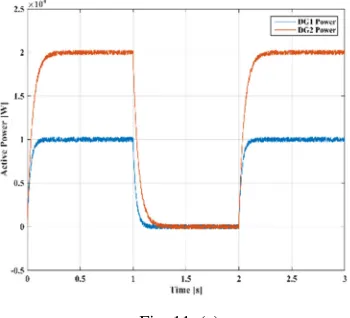
Three-Phase-to-Ground (L-L-G) Short Circuit Fault In this part, an L-L-L-G fault occurs at the PCC and the active and reactive output powers of all single-phase and three-phase DG units in the range of fault will be zero due to
direct connection to the fault point; this is shown in Fig. 11.
Fig. 12 demonstrates the dq- voltage at the PCC, under different faults. It can be seen that in the case of
three-phase-to-ground fault, because the voltage of all phases are simultaneously zero, the voltage of d-axis (similar to the q-axis) will also be zero. In L-G and L-L-G faults, because the voltage of only one or two phases is zero, the q-axis voltage is non-zero, and the value of the d-axis voltage is decreased.
International Journal of Industrial Electronics, Control and Optimization .
© 2019 IECO 35(b)
(d)
Fig. 11. (a)- Active power output of the single-phase DGs, (b)- Reactive power output of the single-phase DGs, (c)- Active power output of the three-phase DGs, and (d)- Reactive power output of the three-phase DGs under L-L-L-G fault conditions.
(a)
(c)
(b)
VII.
C
ONCLUSIONSThe desirable power sharing among DG resources in the microgrid is necessary to keep a reliable power supply to AC electrical loads. In this paper, a power management scheme in a three-phase and single-phase DGs-based microgrid using a power control strategy based on new SMC. There were three single-phase DGs that include PV, FC and battery storage units and two three-phase PV units in a multi-bus microgrid. All DG resources were modeled dynamically. The considered robust control method was designed for power components control of DG resources in the microgrid. The proposed control strategy has many advantages such as fast dynamic response, low steady state error, voltage and frequency stability and improving the microgrid performance under balanced loading and fault conditions. The effectiveness of the proposed power control method has been verified by simulation results in Matlab/Simulink software under different types of faults and loadings, and the results were compared with the conventional PI controller. It should be noted that constraints such as the amount of load charge, filter capacity and the capacity of DG units should be considered in the design domain of the controller. At last, the future research directions can be focused on the power management strategies of AC/DC hybrid microgrids.
R
EFERENCES[1] Z. Yi, W. Dong, and A.H. Etemadi, “A Unified Control
and Power Management Scheme for PV-Battery-based Hybrid Microgrids for both Grid-Connected and Islanded
Modes,” IEEE Transactions on Smart Grid, Vol. PP, No.
99, p. 1–1, 2017.
[2] M. Cucuzzella, G.P. Incremona, A. Ferrara, “Design of
Robust Higher Order Sliding Mode Control for
Microgrids,” IEEE Journal of Emerging and Selected
Topics in Circuits and Systems, Vol. 5, No. 3, pp. 393-401, 2015.
[3] B. Kroposki, C. Pink, R. DeBlasio, H. Thomas, M. Simoes,
P.K. Sen, “Benefits of Power Electronic Interfaces for
Distributed Energy Systems,” IEEE Transactions on
Energy Conversion, Vol. 25, No. 3, pp. 901-908, 2007.
[4] M. Yazdanian and A. Mehrizi-Sani, “Distributed Control
Techniques in Microgrids,” IEEE Transactions on Smart
Grid, Vol. 5, No. 6, pp. 2901–2909, 2014.
[5] H.R. Baghaee, M. Mirsalim, G.B. Gharehpetian, H.A.
Talebi, “Application of RBF Neural Networks and
Unscented Transformation in Probabilistic
Power-Flow of Microgrids including Correlated Wind/PV Units and Plug-In Hybrid Electric
Vehicles,” Simulation Modelling and Practice and Theory.,
Vol. 72, No. C, pp. 51-68, 2017.
[6] N. Hatziargyriou, H. Asano, R. Iravani, and C. Marnay,
“Microgrids,” IEEE Power and Energy Magazine, Vol. 5,
pp. 78-94, 2007.
[7] A.G. Tsikalakis, and N.D. Hatziargyriou, “Centralized
Control for Optimizing Microgrid Operation,” IEEE
Transactions on Energy Conversion. Vol. 23, pp. 241-248, 2008.
[8] P. Shanthi, U. Govindarajan, D. Parvathyshankar,
“Instantaneous Power-Based Current Control Scheme for VAR Compensation in Hybrid AC/DC Networks for Smart Grid Applications”,
IET Power Electronics, Vol. 7, No. 5, pp. 1216- 1226, 2014 .
[9] M. Hamzeh, A. Ghazanfari, H. Mokhtari, and H. Karimi,
“Integrating Hybrid Power Source Into an Islanded MV Microgrid Using CHB Multilevel Inverter Under
Unbalanced and Nonlinear Load Conditions,” IEEE
Transactions on Energy Conversion. Vol. 28, No. 3, pp. 643-651, 2013.
[10] P. Thounthong, A. Luksanasakul, P. Koseeyaporn, and B.
Davat, “Intelligent Model-Based Control of a Standalone Photovoltaic/Fuel Cell Power Plant With Supercapacitor
Energy Storage,” IEEE Transactions on Sustainable
Energy, Vol. 4, No. 1, pp. 240-249, 2013.
[11] X. Liu., P. Wang, P. C. Loh, “A Hybrid AC/DC Microgrid
and its Coordination Control,” IEEE Transactions on
Smart Grid, Vol. 2, No. 2, pp. 278-286, 2011.
[12] A. Milczarek, M. Malinowski, J. M. Guerrero, “Reactive
Power Management in Islanded
Microgrid-Proportional Power Sharing in
Hierarchical Droop Control,” IEEE Transactions
on Smart Grid, Vol. 6, No. 4, pp. 1631-1638, 2015.
[13] E. Barklund, N. Pogaku, M. Prodanovic, C.
Hernandez-Aramburo, and T. C. Green, “Energy
Management in Autonomous Microgrid Using
Stability-Constrained Droop Control of Inverters,” IEEE
Transactions on Power Electronics., Vol. 23, No. 5, pp. 2346–2352, 2008.
[14] F. Shahnia, R. Majumder, A. Ghosh, G. Ledwich, F. Zare, “Operation and Control of a Hybrid Microgrid Containing Unbalanced and Nonlinear Loads,” Electric Power Systems Research, Vol. 80, No. 8, pp. 954-965, 2010.
[15] B. Kroposki, R. Lasseter, T. Ise, S. Mororzumi, S.
Papathanassiou, and N. Hatziargyriou, “A Look at Microgrid Technologies and Testing Projects from around the World,” IEEE Power and Energy Magazine, Vol. 6, No. 3, pp. 40-53, 2008.
[16] N. W. A. Lidula, and A. D. Rajapakse,
“Microgrids Research: A Review of Experimental
Microgrids and Test Systems,” Renewable and Sustainable
Energy Reviews, Vol. 15, No. 1, pp. 186-2020, 2011.
[17] P. Chiang, D. Li, Y. K. Chai, and F. Blaabjerg,
“Autonomous Control of Interlinking Converter with
Energy Storage in Hybrid AC-DC Microgrid,” IEEE
Transactions on Industry Applications, Vol. 49, No. 3, pp. 1374-1382, 2013.
[18] I. Mitra, T. Degner, M. Braun, “Distributed Generation and Microgrids for Small Island Electrification in
Developing Countries: A Review,” SESI Journal, Vol. 18,
No. 1, pp. 6-20, 2008.
[19] P. Li, X. Yu, J. Zhang, and Z. Yin, “The H∞ Control
Method of Grid-Tied Photovoltaic Generation,” IEEE
Transactions on Smart Grid, Vol. 6, No. 4, pp. 1670-1677, 2015.
[20] M. Hosseinzadeh, and F.R. Salmasi, “Power
Management of an Isolated Hybrid AC/DC Micro-Grid
with Fuzzy Control of Battery Banks,” IET Renewable
Power Generatio, Vol. 9, No. 5, pp. 484-493, 2015.
[21] A. Hussain, V.H. Bui, and H.M. Kim, “A Resilient and
Privacy-Preserving Energy Management Strategy for
Networked Microgrids,” IEEE Transactions on Smart
International Journal of Industrial Electronics, Control and Optimization .
© 2019 IECO 37[22] A. Parisio, E. Rikos, and L. Glielmo, “A Model
Predictive Control Approach to Microgrid Operation
Optimization,” IEEE Transactions on Control Systems
Technolog, Vol. 22, No. 5, pp. 1813-1827, 2014.
[23] H.R. Baghaee, M. Mirsalim, G.B. Gharehpetian,
“Multi-Objective Optimal Power Management and Sizing of a Reliable Wind/PV Microgrid with Hydrogen Energy Storage using MOPSO,” Journal of Intelligent and Fuzzy System, Vol. 32, No. 3, pp. 1753-1773, 2016.
[24] J. Duncan Glover, M.S. Sarma, and T.J. Overbye, “Power
System Analysis and Designs,” 5th Edition, Thomson
Learning, Stamford, USA, 2011.
[25] A.H. Kasem Alaboudy, H.H. Zeineldin, and J. Kirtley,
“Microgrid Stability Characterization Subsequent to
Fault-Triggered Islanding Incidents,” IEEE Transactions
on Power Delivery, Vol. 27, No. 2, pp. 658-669, 2012.
[26] C.L. Moreira, and J.A. Pecas Lopes, “Microgrids
Operation and Control under Emergency Conditions,”
Intelligent Automation and Soft Computing, Vol. 16, No. 2, pp. 255-272, 2010.
[27] M.E. Baran, I. El-Markaby, “Fault Analysis on
Distribution Feeders with Distributed Generators,” IEEE
Transactions on Power Systems, Vol. 20, No. 4, pp. 1757-1764, 2005.
[28] T.C. Ou, “Ground Fault Current Analysis with a Direct
Building Algorithm for Microgrid Distribution,”
International Journal Electrical Power and Energy Systems, Vol. 53, pp. 568-875, 2013.
[29] M.Jain, S. Gupta, D. Masand, and G. Agnihotri, “Analysis
of a Microgrid under Transient Conditions Using Voltage
and Frequency Controller,” Advances in Power
Electronics, 2012.
[30] G.P. Incremona, M. Cucuzzella, A. Ferrara,
“Adaptive Sub-Optimal Second-Order Sliding Mode
Control for Microgrids“, International Journal of Control,
Vol. 89, No. 9, pp. 1849-1867, 2016.
[31] Y. A. I. Mohamed, H. H. Zeineldin, M. M. A. Salama, and
R. Seethapathy, “Seamless Formation and Robust Control of Distributed Generation Microgrids via Direct Voltage
Control and Optimized Dynamic Power Sharing,” IEEE
Transactions on Power Electronics, Vol. 27, No. 3, pp. 1283-1294, 2012.
[32] S. K. Gudey, and R. Gupta, “Sliding-Mode Control in
Voltage Source Inverter-based Higher-Order Circuits,”
International Journal of Electronics, Vol. 102, No. 4, pp. 668-689, 2015.
[33] M. E. Ropp, and S. Gonzalez, “Development of a
MATLAB/Simulink Model of a Single-Phase
Grid-Connected Photovoltaic System,” IEEE Transactions
on Energy Conversions, Vol. 24, No. 1, pp. 195-202, 2009.
[34] R.I. Putri, S. Wibowo, and M. Rifa, “Maximum Power
Point Tracking for Photovoltaic using Incremental
Conductance Method,” Energy Procedia, Vol. 68, pp.
22-30, 2015.
[35] L. Wang, and D.J. Lee, “Load-Tracking Performance of an
Autonomous SOFC-Based Hybrid Power
Generation/Energy Storage System,” IEEE Transactions
on Energy Conversion, Vol. 25, No. 1, pp. 128-139, 2011.
[36] O. Tremblay, L. A. Dessaint, and A. I. Dekkiche, “A
Generic Battery Model for the Dynamic Simulation of Hybrid Electric Vehicles,” in Proc. IEEE Vehicle Power and Propulsion Conference (VPPC 2007), pp. 284–289, 2007.
[37] S. Dasgupta, S.K. Sahoo, S.K. Panda, “Single-Phase
Inverter Control Techniques for Interfacing Renewable
Energy Sources with Microgrid-Part I: Parallel-connected Inverter Topology with Active and Reactive Power Flow
Control along with Grid Current Shaping,” IEEE
Transactions on Power Electronics, Vol. 26, No. 3, pp. 717-731, 2011.
[38] H.K. Khalil, and J.W. Grizzle, “Nonlinear Systems,” Vol. 3, Prentice Hall, Englewood Cliffs, NJ.
[39] A.A. Ahmad, A. Abrishamifar, S. Elahian, “Fixed
Frequency Sliding Mode Controller for the Buck Converter,” In: Proceedings of 2nd Power Electronics, Drive System, Technology Conference, Tehran, Iran, pp.557-561, 2011.
Reza Sedaghati was born in Kazeroon, Iran, in
1983. He received his M.Sc. degree in Electrical
Engineering in 2009. He is currently as a Ph.D. student in Department of Electrical Engineering of Lorestan, Khorramabad, Iran. His research interests include dynamic and control of power system, renewable energies, optimization, and
FACTS devices.
Mahmoud Reza Shakarami was born in Khorramabad, Iran, in 1972. He received his
M.Sc. and Ph.D. degree in Electrical
Engineering from Iran University of Science
and Technology, Tehran, Iran, in 2000 and 2010,
IECO