Iranian Journal of Electrical & Electronic Engineering, Vol. 11, No. 3, Sep. 2015 276
Applicability Improvement and Hysteresis Current Control
Method Simplification in Shunt Active Filters
H. Heidarzad Moghaddam*(C.A.) and M. Salimi*
Abstract: Hysteresis current control method is widely used in Pulse Width Modulation (PWM) inverters because of simplicity in performance, fast control response and good ability in limiting peak current. However, switching frequency in hysteresis current control method with fixed bandwidth has large variation during a cycle and therefore causes non-optimal current ripple generation in output current. One of basic problems in implementing hysteresis current control is its variable switching frequency that causes sound noise and increase in inverter losses and also high frequency current components injection to the source current. In this paper, a fixed frequency hysteresis current controller is proposed for grid connected inverters. In the proposed approach, the required bandwidth of the controller is calculated according to system parameters. Also, the derivative of the reference current is eliminated to solve the problems associated with practical implementation of the converter. Finally, a shunt active filter has been used for removing the current harmonic components generated by non-linear loads. Proposed method is simple to perform and reliable, and also has been simulated in MATLAB software environment.
Keywords: Harmonic Spectrum, Hysteresis Bandwidth, Optimized Hysteresis Bandwidth, Simplified Hysteresis Bandwidth, Shunt Active Filter.
1 Introduction1
Because of power electronics development in recent years, use of nonlinear loads in electric distribution network has increased significantly. Often, these types of loads consist of diode or transistor rectifier and are used vastly in speed controller of DC and AC motors, uninterruptible power supply, battery charger and else. In fact these types of loads use energy but at the price of harmonic current generation (These loads consume energy at expense of harmonic generation) [1, 2]. Current harmonics existence in distribution power network causes voltage waveform distortion at the Point of Common Coupling (PCC). Power quality distortion especially the voltage and current harmonic cause increase in losses of lines, decrease in power factor and resonance creation in power system. Also, instrumentation systems, and communication and control equipments are possibly affected by Electro-Magnetic Interference (EMI) of high frequency harmonics [3]. For this reason, quality has high
Iranian Journal of Electrical & Electronic Engineering, 2015. Paper first received 08 Mar. 2015 and in revised form 14 Apr. 2015. * The Authors are with the Department of Electrical Engineering, Ardabil Branch, Islamic Azad University, Ardabil, Iran.
E-mails: [email protected] and [email protected].
importance with regard to the energy generation and consumption.
In conventional power systems, LC passive filters, because of their high efficiency and relatively low cost, are used to remove network current harmonics and also power factor correction.
However, network impedance has major effect on operation procedure and also, there is a possibility of series and shunt resonance with load and power supply when using these filters. To overcome these problems using shunt Active Power Filters (APF) has been discussed and in recent years many researchers have investigated aforementioned subject [4-8].
Shunt Active Power Filters (APF) consists of one Voltage Source Inverter (VSI). Although it is common to use the voltage control or current control or both of them to control inverters but, usually, use of current control is preferred to other controlling methods to control shunt Active Power Filters (APF) because this filter is used for load current harmonic correction. There are three common methods to control current of a voltage source inverter in shunt active power filters as follows [9-12]:
1-Linear current control 2-Digital current control 3-Hysteresis current control
Heidarzad M Hysteresi because of s use of hyste because its and also syst response [13
Unfortun frequency an known as asp Change decrease in l noise and low
Use of pa increase in s harmonic inj these filters switching fr losses. To overc have been proposed h schedulable [14], but us instability pr states, it is p calculated hy induction m previous pr hysteresis wi relatively lon be used in re
Bandwidt exactly. Un appears in equations ha also simulati differentiator instability differentiator recommende In this p calculation is equation is s necessary. In application method in sh
To prove shunt filter ( section - has toolbox.
2 Shunt Ac Main par voltage sour capacitor. Cu with harmon filter at the therefore, ne
Moghaddam & is current co simplicity in resis current control loop tem paramete ]. nately, nowa nd its change i pects of hyster in inverter longevity of w order harmo assive heavy f switching freq jection to ne
are very exp requency can
come these pr presented [1 hysteresis cur width using se of PLL w
roblems. In a possible that ysteresis width motors [15]. roblems we idth is not ac ng time for ca eal time applic th was calc nfortunately,
these equat ave been verif
ion studies, b r in electron
problems. F r in indus ed.
paper, a new s proposed. In implified so t n practice, rem
and simplifie hunt active filt
e the accuracy (cascade) - w s been simula
ctive Filters t of shunt acti rce inverter t urrent harmon nic componen
Point of Co etwork harmon
& Salimi: Appl ontrol method
implementatio control metho current respo er changing do
adays, varia in a certain in resis current c switching fr semiconducto onic generatio filters in inver quency can pr etwork but it
pensive and n increase inv
roblems many 14-17]. Tent rrent control
Phase Lock with passive b
ddition to lon PLL become h to fix switch Although, ere solved, ccurate enough alculation. The cations. culated in p
reference c tions [18]. A
fied with imp but it is obv nic circuit ca
For this re strial applic
method for n this method, that use of dif moving differe es hysteresis ters.
y of proposed which is discu
ated with MA
ive filters, sho that is connec nic compensat
nt injection ommon Coup nic componen
licability Impr d is vastly u on. In additi od has increa onse is desira oes not affect
able switch nterval have b control metho requency cau ors switches, on.
rter output and revent low or is obvious t also increase verter switch
y research pap ti and Malis l method w ked Loop (PL big filter cau ng time transi es instable. B hing frequency
in this meth but calcula h and also ne erefore, it can
apers [16, 1 current deriv Although, th plementation
ious that use auses noise eason, use cations is
hysteresis wi , hysteresis wi fferentiator is entiator impro current con
d method, act ussed in the n ATLAB\Simul
own in Fig. 1, cted to DC s tion is perform
by shunt act ling (PCC), nt is removed
rovement and used ion, ased able t its hing been d. uses and d/or rder that e in hing pers sani with LL) uses ient Bose y in hod ated eeds nnot 17], vate hese and e of and of not idth idth not oves ntrol tive next link is a side med tive and d. In thi imp sta rea Bo 100 use inc pro wo the fre loa cur one 1-F 2-I 3-S cal [3] is cur ins use com are ( p ( q wh AC com com act com exp Fig Hysteresis Cu s way, powe proved.
In a shunt andards, powe ason switching ounded rating 00 A) and hig e of shunt ac crease maximu Use of two ocedure signi orks in a diffe e inverter nea equency and ad.
Several meth rrent harmon es are categor Fast furrier tra Instantaneous Synchronous r In this paper lculated by us ]. Based on us
able to com rrent harmoni stantaneous co
ed to calcu mponents of a e defined as fo ( ). ( )
(t =Vα t iα t ( ). (
) V t i t
t = α β
hich, in above C components
mponents of a mponents are
With regard tive power b mponent by in pressed as:
g. 1 Shunt Activ
urrent Contro er quality in
t active filte r switches wo g losses play
of power sem gh level of sw ctive filter in um system ou o shunt filter ficantly. In s erent switchin ar to the load has to comp
hods have be nic componen rized as follow ansform.
reactive powe reference axis r, inverters ref e of instantan sed reference mpensate reac
ic and balanc omponents of ulate referenc active power p ollows:
( ). ( ) V t i t t + β β
( ). (
) V t i t
t − β α
e equations p(t s. DC compo active and rea related to har d to compens by inverter ( nverter (2), in
ve Power Filter
l Method … aforemention
er to achiev ork in range of
vital role in miconductors witching losse n cascade con utput power [1
s improves c such system,
ng frequency. works in low ensate reactiv
een proposed nts which mo ws: er theory. s theory. ference signal neous reactive signals, shun ctive power, ce network. In f power p(t) ce signal. p(t) and reacti )
)
t) and q(t) inc onents are rel
active powers rmonic compo sating main c (1) and curre nverter side cu
rs (APF).
277 ned system is
ve harmonic f kHz; for this shunt filters. (100 A< I < es have led to nfiguration to
9].
compensation each inverter In this case, wer switching ve power for
to detect the ost important
ls of filter are power theory nt active filter remove load n this method and q(t) are Instantaneous ive power q(t)
(1)
(2) clude DC and lated to main and also AC onents. component of
ent harmonic urrents can be s c s . < o o n r , g r e t e y r d d e s ) d n C f c e
278 Fig. 2 Source
1
1
1
2 . 3 ia ib ic
⎡ ⎢ ⎡ ⎤
⎢
⎢ ⎥ = ⎢
⎢ ⎥ ⎢ ⎢ ⎥ ⎣ ⎦
⎢⎣
2
2
2
2 . 3 ia ib ic
⎡ ⎤ ⎢ ⎥ = ⎢ ⎥ ⎢ ⎥ ⎣ ⎦
where, in a related to rea components block diagram (1) and (2) ar
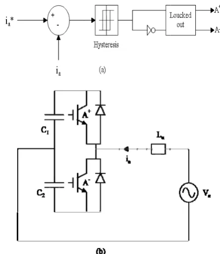
3 Control o If inverte current uses of inverter an When line current deter switched so fixed range c
of reference cu
1 0
3 1
2 2
3 1
2 2
V V
α
β
⎡
−
− ⎣
− ⎡ ⎢ ⎢⎣
1 0
3 1
2 2
3 1
2 2
V Vβ
⎡ ⎢ ⎢− ⎢ ⎢ − ⎢⎣
− ⎡ ⎢ ⎢⎣ above equatio
active power, of active an m of referenc re shown.
of Improved er null point co
three similar c nd its related
current is gr rmined with
that current i continuously [
Ir
urrent.
2 2
1
. .
( )
0 ( )
V V
V
V q t
α β
β
α
⎤ ⎥ ⎥
⎥ +
⎥ ⎥⎦
⎤ ⎡ ⎤ ⎥ ⎢ ⎥ − ⎥ ⎣⎦ ⎦
2 2
1 .
2 ( )
2
V V
V V p
V q
α β
α β
α
⎤ ⎥ ⎥
⎥ +
⎥ ⎥⎦
⎤ ⎡ ⎥ ⎢ − ⎥ ⎣⎦
ons q(t) is )
( ~ t
p and q~
nd reactive po ce signal gene
Hysteresis C onnected, con controllers pe controller are reater (lower)
hysteresis w is decreased a [20, 21].
ranian Journa ⎤
⎦
.
( ) ( ) p t
t
⎤ ⎥ ⎦
DC compon
)
(t are harmo owers. In Fig erator for inve
Current ntrol of hyster
r phase. One a shown in Fig ) than refere width, inverter and remains i
al of Electrica (3)
(4)
nent onic g. 2 erter
esis arm g. 3. ence r is in a
Fig
filt
Fig
me
con
hys cur sw inc cur on equ wr
l & Electronic g. 3 Current c ers (a), Single p
g. 4 Voltage
thod.
To exactly nnected to net
Fig. 4 shows steresis curr rrent gets to witch A is tu crement which rrent to get to at this instan uations in tim
itten as follow
c Engineering
control loop in phase half bridg
and current in
analyze th twork, which s the voltage ent control
the lower bo urned on to h is shown in
the upper bou nt. By ignoring me interval b ws:
g, Vol. 11, No.
n conventional ge grid connect
n hysteresis c
his, consider is shown in F
and current w method. W ound of refer increase curr
the figure as und and switc g reactor resis between t1 an
3, Sep. 2015
l active power ed inverter (b).
current control
inverter A ig. 3. waveforms in When inverter rence current, rent. Current Ia causes the
ch A is turned stance, below nd t2 can be r
l
A
n r , t e d w e
Heidarzad Moghaddam & Salimi: Applicability Improvement and Hysteresis Current Control Method … 279 It is assumed that, Vc1 = Vc2 = VDC/2.
1
1 1
: ( )
2
a DC
c a a
a a
di V
A is on V V V
dt L L
+
+ = − = ⎛ − ⎞
⎜ ⎟
⎝ ⎠ (5)
2
1 1
: ( )
2
a DC
c a a
a a
di V
A is on V V V
dt L L
−
− = − + = − ⎛ + ⎞
⎜ ⎟
⎝ ⎠ (6) From geometric design of Fig. 4 and considering that reference current during switching time intervals is almost linear, below equations can be written:
δ
2 ). (i+ −i* t1 = dt
d a
a (7)
δ 2 ). (i−−i* t2=−
dt d
a
a (8)
s s
f T t
t1+ 2= = 1 (9)
where, in above equations index δ is hysteresis width and index fs is switching frequency.
By summing Eqs. (7) and (8) and substituting in Eqs. (5), (6) and (9), we have Eq. (10):
⎥ ⎦ ⎤ ⎢
⎣ ⎡
+ =
−
dt di V L f V
L t
t a
a a s DC
a *
1 2
1 ) . (
2 (10)
By subtracting Eqs. (7) and (8) and substituting in Eqs. (5), (6) and (9), we have Eq. (11):
) (
2 4
* 1
2
dt di L V
L f V t
t
a
a a
a s DC
+ − = −
δ
(11)
By use of Eqs. (10) and (11), hysteresis width can be written for phase A as below Eq. (12):
⎥ ⎥ ⎦ ⎤ ⎢
⎢ ⎣ ⎡
⎟⎟ ⎠ ⎞ ⎜⎜
⎝
⎛ +
− =
2 *
2 2 4 1
8 dt
di L V V
L L
f
V a
a a
DC a
a s DC
δ (12)
In applications related to shunt active filters, reference current can be considered as sum of reactive current components. So if Va=Vmsin(wt), references
currents can be written as below Eqs. (13), (14) and (15).
* * *
h q
a i i
i = + (13)
wt Cos I
iq*= q (14)
... ) 3 ( )
2 ( )
2
( 2 3
2
*=I Sin wt +I Cos wt +I Cos wt +
ih hs hc hc (15)
To compensate high frequency harmonic components, it is clear that switching frequency of harmonic compensator (APF2) should be greater than switching frequency of reactive compensator (APF1). Considering the fact that increase in switching frequency leads to decrease in maximum output power of inverter, cascade compensation is vastly used in practical applications. In this system which is shown in Fig. 5, the task of filter (1) is reactive current component compensation and its switching frequency is 1 kHz approximately.
Fig. 5 Shunt filter (cascade).
In practice, low switching frequency in inverter leads to higher output power. The task of filter (2) -which is a high frequency inverter- is harmonic component compensation and it works around 10 kHz. It is obvious that because inverter (2) operates in high frequency, its output power is much less than maximum output power of inverter (1).
Recent equations show that switching frequency of inverter (necessary time for current increase or decrease) is a function of DC capacitor, coupling reactor, network voltage and hysteresis width. Since DC side voltage and coupling reactor are almost constant, it is evident that by changing voltage of network during one cycle, in hysteresis current control with fixed width, switching frequency cannot be constant.
In other words, considering change in network voltage, hysteresis width should be modified so that inverter switching frequency remains constant. This means that in hysteresis current control method with constant frequency, hysteresis width cannot be constant. Reactive and harmonic component separation will improve system’s general operation significantly. Equations (3) and (6) show that output current rises and fall times depend on coupling reactor. With regard to relatively fast change of current in filters (1) and (2), to create current controllability in hysteresis method, the inductance value of coupling reactor should be selected relatively small. From Eqs. (5) and (6), it can be concluded that decrease in the value of coupling reactor leads to increase in slop of reactor current changing. Usually, the inductance value of coupling reactor is selected about 100 µΗ in practical applications.
In cascade compensation, Eq. (12) can be written for inverters (1) and (2) as below Eqs. (16) and (17).
⎥ ⎥ ⎦ ⎤ ⎢
⎢ ⎣ ⎡
⎟⎟ ⎠ ⎞ ⎜⎜
⎝ ⎛
− −
=
2
2 2
1 sin
4 1
8 L I wt
V V
L L
f V
q a a
DC a
a s DC
δ (16)
⎥ ⎥ ⎥
⎦ ⎤
⎢ ⎢ ⎢
⎣ ⎡
⎟ ⎟ ⎟
⎠ ⎞
⎜ ⎜ ⎜
⎝ ⎛
+ − +
− =
2
2 2 2
2
... ) 2 sin( 2
) 2 cos( 2
4 1 8
wt w I
wt w
I L V V
L L
f V
hc hs a a
DC a
a s DC
δ (17)
280 Iranian Journal of Electrical & Electronic Engineering, Vol. 11, No. 3, Sep. 2015 It is clear that due to different switching in inverter
(2):
q hc
hs hc
hs I I I I
I 2 , 2 , 3 , 3 ,... << (18)
In this system because of very small value of La, both value of
dt diq* and
dt
dih* compared to va/La can be ignored (in applications related to shunt active filters and use of cascade configuration). For this reason, hysteresis width in applications related to shunt active filters can be simplified as below Eqs. (19) and (20):
⎥ ⎥ ⎦ ⎤ ⎢
⎢ ⎣ ⎡
⎟⎟ ⎠ ⎞ ⎜⎜ ⎝ ⎛ − =
2
2 2 4 1
8 a
a
DC a
a s DC
L V V
L L
f V
δ (19)
⎥ ⎦ ⎤ ⎢
⎣ ⎡
−
= 1 422
8 DC
a
a s DC
V V L
f V
δ (20)
Equation (20) show that hysteresis width changes according to change in Va until the frequency is fixed. In
new method, calculation of hysteresis width has been expressed based on (20); Hysteresis width is regulated according to Va changing so that low frequency
distortion of Va is optimized in output current
waveform.
4 Simulated System
New proposed method for hysteresis width calculation is simulated in this section. Main part of system is two voltage source inverters with IGBT switches which are directly connected to network by coupling reactors. Neutral point of network is connected to midpoint of inverters’ DC link so zero sequence power can be transferred between network and inverter. A Three phase rectifier with one RL load was used to implement a nonlinear load.
Switching frequency of inverter (1) was 1 kHz approximately, and it has the task of compensating the main component of load reactive power. Current harmonic components of load are compensated by inverter (2) and its switching frequency is 10 kHz approximately.
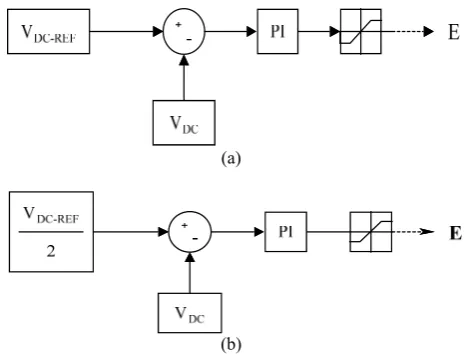
The controller of inverter DC link is shown in Fig. 6. It can be seen that this controller is implemented by a simple PI. In this system, first voltage of DC link is compared to reference value.
Fig. 6 DC link controller.
(a)
(b)
Fig. 7 DC link stabilizer (a), PI controller (b).
Fig. 8 Final generated reference current in filter (1).
Based on generated error value, PI controller calculates necessary active power so that DC voltage link is bounded in a fixed value under switching losses and steady state losses of circuit switches. To improve optimal operation of system, reference voltage level of DC link capacitors is selected 800 volt.
Although, DC link controller can fix total voltage of DC side, but after a few cycles, the voltages of capacitors C1 and C2 relative to each other are severely unbalanced. To balance the voltage of capacitors C1 and C2, PI controller is used as shown in Fig. 7(b). This controller based on voltage unbalance level of two capacitors, adds security component to three phase reference currents which is shown in Fig. 8. The final generated reference current is applied to hysteresis current controller which its width is calculated by Eq. (20). In this equation, it is assumed that the values of VDC, L and fs are constant. In this equation because only
network voltage is variable, necessary circuit to implement the hysteresis width controller will be very simple. Simulation parameters have been shown in Table 1.
Heidarzad M Table 1 The in
DC link Couplin Fundam DC link DC link DC link DC link DC link
Fig. 9 Hystere
Fig. 10 Outpu
5 Simulati To analy calculating h
Moghaddam &
nformation of s k capacitors (c1, ng inductors (La mental frequency
k voltage refere k voltage contro k voltage contro k voltage balanc k voltage balanc
esis width chang
ut current of filte
on Results yze operation
hysteresis ban
& Salimi: Appl
simulation param ,c2)
a, Lb, Lc) y nce oller KP oller KI cer KP cer KP
ge in filters (1)
ers (1) and (2).
of new prop ndwidth, desc
licability Impr
meters. 1000 μf 1000 μH 50 Hz 800 V 10 0.5 0.5 0.1
and (2).
osed method cribed system
rovement and for
m in
pre MA is (1) (2) of wit bas pha is ohm
cur imp dis filt tha int
Fig
(2) Pro
Fig
Hysteresis Cu evious section ATLAB. Fig.
the changing ) and (2) in ph ) have been sh (20), frequen th two fixed sed on (20) h ase full bridg considered as m and inducto In hysteresis rrent includes portant than stributed in a tering difficul at harmonic co
eger products
g. 11 Output cu . Conventional oposed new met
g. 12 Controller
urrent Contro n has been 9 which show
procedure of hase A. outpu hown in Fig. ncy spectrum hysteresis w have been dep e rectifier wit s the nonline or is 0.01 H.
current contr s a large am n it, its ha a large area lt. In method omponents of s of one freque
urrent frequenc l method with thod A-1 and B
r response and D
l Method … simulated wi ws this control f hysteresis w ut currents of f 10. To verify m of filters’ o width method
picted in Fig. th resistive- in ear load. Its r
rol with fixed mount of ripp armonic com which in pr based on (20 ften concentra
ency.
cy spectrum of h fixed width B-1.
DC side stabiliz
281 ith Simulink/ ller’s outputs, width of filter filters (1) and y the accuracy output current and method 11. A single nductive load resistor is 40
width, output ple and more mponents are ractice makes ), it is shown ate around the
f filters (1) and A-2 and B-2,
zer.
/ , r d y t d e d 0
t e e s n e
d ,
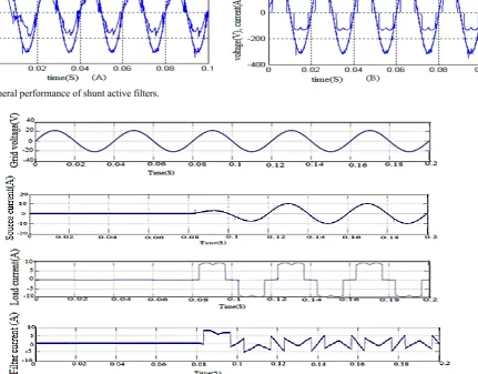
282 Fig. 13 Genera
Fig. 14 dynam
In Fig. 1 control syste of the load t = 0.04 s a n is clear that i from zero to completely s
6 Conclusi In this pa use in shunt New propo advantages in
1-There a proposed m components.
2-New pr implement b equation can As can b frequency w output curre
al performance
mic response of
14 the dynam em is illustrate current is as nonlinear load in spite of ste o nominal val table with ver
ion
aper, hysteres t active filters sed method n practical app are no noise an method due
roposed meth ecause most p n be assumed c e seen in new was fixed an nt are improv
Ir
of shunt active
the proposed co
mic response ed. In this fig ssumed to be d is connected ep variation of ue, the propo ry fast dynami
sis current con s is simplified is simple plications: nd instability to removing
hod is simple parameters in constant. w proposed m nd harmonic
ved as comp
ranian Journa
e filters.
ontrol system.
of the propo gure, initial va e zero. Then d to the system
f the load curr osed controlle ic response.
ntrol strategy d and optimiz and has bel
problems in n g the derivat
and practica hysteresis wi
method, switch components ared to class
al of Electrica osed
alue , at m. It rent er is
for zed. low
new tive
al to idth
hing of ical
me the app the thi in
Re [1]
[2]
[3]
[4]
l & Electronic ethod (constan ere is a poss
proach with h e current of s s paper can be shunt active f
eferences ] G. T. Hey
and M. J. technolog power qu Electronic ] H. Akagi
IEEE, Vo
] V. E. W
Equipmen 8, No. 2, p ] H. Akagi improving Int. Conf
c Engineering nt bandwidth sibility for u high efficiency hunt active fi e used for ind filters with cas
ydt, S. P. Hoff Kemper, “Th gies on elec uality”, IEEE
cs, ISIE'94., p i, “Active Ha
l. 93, No. 12, Wanger, “Ef nt”, in IEEE T pp. 672-680, A
i, “New tren g power quali f. on Power
g, Vol. 11, No. h).Because of use of this m
y and also sim filters. Propos dustrial applica
scade connect
fman, A. Risa he impact of e ctric distribu E Int. Sym. o
p. 176-181, 1 armonic Filte pp. 2128-214 ffects of Ha Trans Power D
Apr.1993. nds in activ ity”, in Proce Electronics,
3, Sep. 2015 f this reason, method as an mple to control ed method in ation and also tion.
al, R. I. Sasaki energy saving ution system on Industrial 994.
ers”, Proc. of 41, Dec 2005.
armonics on Delivery, Vol. ve filters for eedings of the Drives and , n l n o
i g m l f n .
r e d
Heidarzad Moghaddam & Salimi: Applicability Improvement and Hysteresis Current Control Method … 283 Energy Systems for Industrial Growth, Vol. 1, pp.
417-425, 8-11 Jan. 1996.
[5] L. Moran, L. Fernandez, J. W. Dixon and R. Wallace, “A Simple and Low-Cost Control Strategy for Active Power Filters Connected in Cascade”, IEEE Trans. On Industrial Electronics, Vol. 14, No. 5, Oct. 1997.
[6] A. M. Al-Zamel and D. A. Torrey, “A three-phase hybrid series passive/shunt active filter system”, in Applied Power Electronics Conference and Exposition, 1999. APEC '99. Fourteenth Annual, Vol. 2, pp. 875-881, 14-18 Mar. 1999.
[7] A. Abellan, J. M. Benavent, G. Garcera and D. Cerver, “Fixed frequency current controller applied to shunt active filters with UPF control in four-wire power systems”, in IECON 02, IEEE 28th Annual Conference of the Industrial Electronics Society, Vol. 1, pp. 780-785, 5-8 Nov. 2002.
[8] S. Park, J-H. Sung and N. K. wanghe, “A New Parallel Hybrid Filter Configuration Minimizing Active Filter Size”, IEEE Conf. on Industrial Electronics.1999. PESC 99. 30th Annual IEEE, Vol. 1, pp.400-405, Aug. 1999.
[9] V. R. Stefanovic and R. M. Nelms,
“Microprocessor Control of Motor Drives and Power Converters”, in Tutorial Course Rec., IEEE Conf. 1991.
[10] H. W. Van der Broeck, H. C. Shudelny and G. V. Stanke, “Analysis and Realization of a Pulse Width Modulator Based on Voltage Space Vectors”, IEEE Trans. on Industrial Applications, Vol. 24, No. 2, pp. 142-150, 1988.
[11] D. Wuest and F. Jenni, “Space Vector Based Current Control Schemes for Voltage source Inverters”, IEEE Conf. on Industrial Electronics, 1993. PESC '93 Record., 24th Annual IEEE, pp. 986-992, 20-24 Jun. 1993.
[12] D. M. Brod and D. V. Novotny, “Current Control of VSI-PWM inverters”, IEEE Trans. on Industrial Applications, Vol. IA-21, No. 3, pp. 562-570, Jul./Aug. 1995.
[13] S. Boso, L. Malesani and P. Mattavelli, “Comparison of Current Control Techniques for Active Filter Applications”, IEEE Trans. on Industrial Electronics, Vol. 45, No. 5, pp. 722-729, 1998.
[14] L. Malesani and P. Tenti, “A Novel Hysteresis Control Method for Current Controlled voltage Source PWM Inverters with Constant Modulation Frequency”, IEEE Trans. on Industrial Applications, Vol. 26, No. 1, pp. 88-92, 1990. [15] B. K. Bose, “An Adaptive Hysteresis band
Current Control Technique of a Voltage Fed PWMInverter for Machine Drive System”, IEEE Trans. on Industrial Applications, Vol. 37, No. 5, pp. 402-408, Oct. 1990.
[16] T. W. Chun and M. K. Choi, “Development of Adaptive Hysteresis Band Current Control Strategy of PWM Inverter with Constant Switching Frequency”, IEEE Conf. on Industrial Applications, 1996. Eleventh Annual, Vol. 1, pp. 194-199, 3-7 Mar. 1996.
[17] M. Kale and E. Ozdemir, “A novel adaptive hysteresis band current controller for shunt active power filter”, Control Applications, 2003. CCA 2003. Proceedings of 2003 IEEE Conference on, Vol. 2, pp. 1118-1123, 23-25 June 2003.
[18] W. Dai, B. Wang and Hua Yang, “A hysteretic current controller for active power filter with constant frequency”, Computational Intelligence for Measurement Systems and Applications, 2009. CIMSA '09. IEEE International Conference on, pp. 86-90, 11-13 May 2009.
[19] L. Moran, P. Godoy, R. Wallance and I. Dixon “A new current control strategy for active power filters using three PWM voltage source inverters”, in Power Electronics Specialists Conference, 1993.PESC '93 Record., 24th Annual IEEE, pp. 3-9, 20-24 Jun. 1993.
[20] M. Kale and E. Özdemir, “A new hysteresis band current control technique for shunt active filter”, Control Applications, 2003. CCA 2003. Proceedings of 2003 IEEE Conference on, Vol. 2, pp. 1118-1123, 23-25 June 2003.
[21] V. Ramesh, B. Haritha, P. Rabeya Sulthana and T. M. Diveswar Reddy, “An Adaptive Hysteresis Band Current Controlled Shunt Active Power Filter”, International Journal of Advanced Research in Electrical, Electronics and Instrumentation Engineering. Vol. 3, No. 3, pp. 8031-8040, March 2014.
Haleh Heidarzad Moghaddam was
born in Astara, Iran, in 1989. She received the B.Sc. degree in electrical engineering from the Islamic Azad University (IAU) of Lahijan, Lahijan, Iran, in 2012 and, and the M.Sc. degree in power engineering from the Islamic Azad University (IAU) (Science and Research Branch) of Ardabil, Ardabil, Iran, in 2015.
Mahdi Salimi was born in Ardabil,
Iran, in 1979. He received the B.Sc. and M.Sc. degrees in electrical engineering from K.N.T University of Technology, Tehran, Iran, in 2000 and 2002, respectively, and the Ph.D. degree in power electronics from the Islamic Azad University (IAU) (Science and Research Branch), Iran, in 2012. Since 2003, he has been with IAU, where he is currently an Assistant Professor with the Department of Electrical Engineering. His research interests include power electronics, control engineering, and renewable energy.