Iranian Journal of Electrical and Electronic Engineering, Vol. 15, No. 1, March 2019 56
Effects of Stress Grading Materials’ Properties on the
Performance of 20-kV Cable Terminations
V. Abbasi*
(C.A.), S. Hemmati* and M. Moradi**
Abstract: Stress grading (SG) layer in cable terminations limits the critical electric field and properties of SG materials are important issues which have to be considered during manufacturing and selecting procedure. In this paper, two different types of (SG) materials are analyzed by both theory and test. According to the applied theory, important parameters as: electrical resistivity, breakdown voltage and thermal conductivity are determined by experiments. Experimental steps are defined in the paper with which theory and experiments are matched together to complete the investigation. The paper discusses electro-thermal breakdown theory and quality of two different SG layers based on the test results. The theory and experimental procedure can be used for prediction of breakdown voltage in cable terminations. The employed method is useful for qualifying the cable terminations by users who want to buy and install heat shrink cable terminations.
Keywords: Cable Termination, Stress Grading Tube, Critical Electric Field, Nonlinear Material, Insulation Layers.
1 Introduction1
ABLE terminations connect between points in medium voltage (MV) and high-voltage (HV) networks that makes their use irrefutable. Most of the previous studies focused on the stress grading mass and tube as the essential parts [1, 2]. High percentage of cable terminations faults occurs in triple points which are connection between semiconductor layer, stress control layer and XLPE [1, 4]. Assembly errors and low quality of stress grading material are the two main reasons of the faults [5-8]. Reference [9] studies damaged cable terminations and classifies the main reasons of their puncturing. During installation any carelessness in critical points causes a disaster and the only alternative is the replacement of the cable
Iranian Journal of Electrical and Electronic Engineering, 2019. Paper first received 01 September 2018 and accepted 24 November 2018.
* The authors are with the Department of Electrical Engineering, Faculty of Energy, Kermanshah University of Technology, Kermanshah, Iran.
E-mails: [email protected] and [email protected].
* The author is with the Electrical Engineering Department, Engineering Faculty, Razi University, Kermanshah, Iran.
E-mail: [email protected]. Corresponding Author: V. Abbasi.
termination. The problems become critical when voids, wet, pollution or semiconductor between cable termination layers remain. Furthermore, scraping XLPE has similar effect and causes fault [5, 9]. Low endurance in the voids causes high electric field and high drop voltage on them. Because of high electric field in triple point regions and connections with edges, heating layers should be done by extra care in these areas. In addition, layers surface has to be cleaned for preventing contamination and wet effects which make weakness in the areas [5, 9]. As an example, failure of a 28 kV rated termination occurred one year after installation in 2006 that had caused an outage and pole fire. The examination of the failed termination revealed that the fault was found right in the boundary of the stress grading layer and semiconductor layer of the cable, where a 2 mm gap was found. Another workmanship error occurred when an incorrect length of stress control tube was used that resulted in premature failure of cable termination. There are other reports in [7-8, 10] about workmanship errors that can be studied by installers to be aware of the problems. Harmonic, weather condition for outdoor terminations and partial discharge are the other reasons for fast breakdown in cable terminations [11-14]. Material properties and other breakdown reasons have been discussed in most of the published titles [15-18].
C
Iranian Journal of Electrical and Electronic Engineering, Vol. 15, No. 1, March 2019 57 Materials properties affect electrical field stress in
triple points [1, 3]. Electric field control is essential for all classes of cable termination to avoid tracking and insulation failure, which is achieved by stress grading systems [19]. The electric potential and electric field distribution along the length of the cable termination is an indication of the quality of the SG system [16, 20]. Stress in critical points depends on dielectric coefficient and electrical conductivity. Stress grading tubes with high resistivity are effective in confronting the stress, but they have thermal limits [3, 4]. Capacitive stress grading layers cannot reduce electric field appropriately and for improving operation, their thickness have to be increased that makes them unsuitable for being used in cable termination structures [2]. Nonlinear materials show flexible reactions under different electrical fields and they can control the stresses related to electric filed values [15]. These nonlinear resistive field grading materials are usually composites that are filled with fillers such as silicon carbide (SiC) and doped zinc oxide (ZnO) [18-21]. These are high dielectric constant materials and their concentration determines the degree of nonlinearity that helps relieve the electric stress. The nonlinear resistive SG layer can control the magnitude of the electric stress with the field dependence nature, but consequently produces ohmic heat due to conduction currents. The level of dissipation energy may be beyond acceptable level under normal operating conditions but are not problematic under few tens of microseconds of an impulse [16]. Nonlinear SG characteristics have made their use universal (Medium-voltage cable terminations (20 kV) are usually heat shrink with resistive control stress layer). However, since they need high-tech methods in construction, the cost of cable terminations using nonlinear materials is quite high.
According to the reviewed papers, there is less number of papers analyzing the effects of SG’s electrical conductivity and dielectric constant on its breakdown voltage in common used cable terminations. Furthermore, the previous studies don not contain practical procedures to identify quality of produced SG by a company for being used massively in a network. Thus, this paper presents impacts of using different kinds of materials on cable termination performance. Beside this, SG layer breakdown depends on both electrical and thermal conductivity which have been investigated in this paper for two kinds of SG tubes by a set of tests and equations. This research has many functional points which can be used in practice and can resolve the investigation weaknesses on cable termination.
2 Stress Grading Materials
Different types of stress control such as conductive, reflective, impedance and nonlinear are available. But, the most common one is impedance stress control which
has been used in 20kV cable terminations. Applied materials have high permittivity and regulated specific resistivity. According to [1], combination of cable termination equivalent circuit with stress control can be analyzed like a transmission line model (Fig. 1) in which the voltage-current relation is:
lcosh
lsinh
U x U
l x ZI
lx (1)where U(x) is voltage distribution along stress control, Ul is voltage at the end of stress control, Z is stress control impedance, Il is current at the end of stress control, γ is the propagation constant and l is the length of control stress [1]. Impedance value has an influence on the effectiveness of stress control. In very high impedances, the voltage will be zero at the screen cut and the voltage across the stress control will drop. Therefore, the stress control tube will be under full voltage with a steep slope that will increase electric field intensively in that region. In very low impedances, the voltage at cut screen will be equal to Ul which means that high current will flow in the low impedance layer and electric field stress will move to another place. The main conclusion is using materials with intermediate conductivity. By covering screen cut with these materials, the stress can be controlled. In addition, current density does not exceed from sustainable values. Following pictures show stress grading materials' effects on critical electric field in triple point (triple point is area of connection between XLPE, semiconductor and SG). The results are extracted from movie registered by high speed camera in HV lab [22] and cable termination voltage is changed from 0 kV to 50 kV. The test is done for three situations: 1) cable termination without SG, 2) cable termination with inefficient SG tube and 3) cable termination with perfect SG tube [22]. In Fig.2 and Fig.4 electrical discharge due to high electric field at triple point is observable for the cases without SG tube and with inefficient SG tube. By using inappropriate SG, problem is exacerbated and current distribution occurs from triple points to other areas as shown in Fig.4. SG with adjusted impedance can control stress and prevent distribution of stress to other areas (see Fig.5). The results demonstrate the
Fig. 1 Equivalent circuit of cable termination (the blue part is stress grading layer) [1].
Iranian Journal of Electrical and Electronic Engineering, Vol. 15, No. 1, March 2019 58 (a)
(b)
Fig. 2 a) Cable without stress grading tube and b) Electrical discharge in triple point area [22].
Fig. 3 Cable with stress grading tube [22].
Fig. 4 Cable with inefficient SG [22].
Fig. 5 Cable with perfect SG tube [22].
positive effect of using SG in critical area and importance of choosing appropriate materials for SG tube. Thus, definition of some parameters for evaluating quality of SG tube is an important issue that is discussed in the paper.
2.1 Electro-Thermal Breakdown of Solid Layers
Occurrence of electro-thermal breakdown in SG tube causes the holes as seen in Fig. 7(b). Main reasons for this breakdown should be recognized. It is obvious that the stress grading location is the center of stress in which the thermal loss is quite high. Moreover, when the electrical conductivity is higher than normal values, current flow can warm up the critical areas. In addition to overvoltage, other faults can intensify the situation
resulting in thermal instability. For example, insulation loss is related to electric field and it is converted to thermal form. Insulation loss equation can be written as below
2
0 r tan
PE (2)
where E and tan δ are electric field and dissipation factor (loss angle) respectively. High resistivity and low tan δ in insulation are desirable because they reduce losses. Volumetric density of insulation loss is related to temperature in an exponential form like Eq. (3).
' 00
T T
P T p e (3)
where α is a constant factor and p0' is insulation loss in
temperature T0 (P T
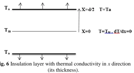
0 p0').Solving a heat transfer exercise, maximum temperature in insulation can be obtained which helps in analyzing electro-thermal breakdown voltage. For the sake of simplicity, some assumptions should be considered:
1) An insulation layer is located between two parallel big conductors in y-z plane.
2) Heat transfer is possible only in x direction.
3) Thermal conductivity (λ) of the insulation is constant and maximum temperature (Tm) occurs in middle of the plane in which dT/dx = 0.
In the steady state (when temperature does not change with time and it is constant) volumetric density of heat transfer per unit time ( '
ab
P ) is equal to:
'
.
ab
P div
gradT (4)In order to prove the validity of this equation, relation between velocity of heat transfer (v) and thermal conductivity can be used.
.
v gradT (5)
Thus, the heat power transferred from the volume (p) is:
n
p
v dS (6)where vn is heat transfer rate at a right angle to the surface (S). If volume is small, volumetric density of heat transfer per unit time can be obtained as below.
' 1
ab n
P v dS
V
(7)where V is volume. According to the Gauss’s theorem one can write:
n
divvdV v dS
(8)
' 1 1
. ab
P divvdV div gradT dV
V V
(9)
Electrical Discharges
Iranian Journal of Electrical and Electronic Engineering, Vol. 15, No. 1, March 2019 59
Fig. 6 Insulation layer with thermal conductivity in x direction (its thickness).
For a small surface and volume, the equation can be rewritten as (10).
' 2
ab
P div
gradT
div gradT
T (10)Since the temperature is allowed to change only in x direction, the volumetric density of heat transfer can easily be evaluated
2 ' 2 ab d T P dx
(11)
Using insulation loss equations (Eqs. (2) and (3)), the last equation will be completed.
0
2 2
0
2 . 0
T T r
d T
E tan e
dx
(12)
In order to solve the differential equation, both sides should be multiplied by dT/dx.
0
2 2 0 1 1 λ 0 2 T T
d dT d
E p e
dx dx dx
(13)
where p0 = ωε0εrtanδ.
Integrating the equation in the range of x=0 to x=d/2 and considering boundary conditions, the following result is obtained.
0 0
2 2
0 0
2
m
T T T T
E p dT e e dx
(14)
0 0 0 2 2 0 2
1 m 0
m T T T T T T E p dT e e dx e
(15)
The exponential function inside the parentheses can be combined.
0
2 2 0 2 1 m m T T T T dT E p dx e e (16)
The variables are separated and the equation is integrated as follows
0
/ 2 2 0 0 2 1 a m m m T d T T T T T E p dT
E e dx
e
(17)where Ta is temperature of the layer boundary. To solve the left side equation, a classic form can be employed as following.
1
2 2 cosh
dx x C a x a
(18) 0 1 2 2 0 cosh 2 2m a m a
a
T T T T
T T
U e e
p e
(19)
It is assumed that U=E.d. By forming a function like f, briefing the equation is possible.
Δ
2 cosh1 2 m a m a
T T T T
m
f T e e
(20)
0
0
2
2 . Δ
a m
T T
U f T
p e
(21)
where f (α∆Tm) is a nonlinear equation and as the voltage increases, its values increases up to a certain level. Beyond this level, unstable changes start and the insulation cannot thermally withstand. The temperature difference between points with maximum value (Tm) and boundaries points (Ta) in insulation has a limit point. In the unstable mode, increasing voltage causes high temperature in Tm area and it passes the limit point that burns insulation (Fig. 6). Function f (α∆Tm) has a definite value in the critical voltage. It is constant in critical point and Eq. (21) in the changed form can be written as following.
0
0
2
2 .
a
cr T T
U cte
p e
(22)
This equation shows that the critical voltage can be defined for different insulation conditions. According to the equation, insulations with high thermal conductivity and low tan δ can pass network stress easily. The equation also shows that the breakdown voltage is sensitive to the quality of insulation, material properties and temperature difference. In the following part, these conclusions are used for a practical study.
3 Studying Two Kinds of Stress Grading Materials
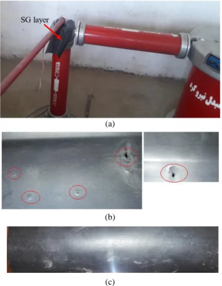
Clarification of the topic needs more studies and real results. Thus, two kinds of SG tubes are chosen as case studies and a set of tests are accomplished. SG tubes under AC voltage stress break down at a definite voltage. During the test, voltage should be increased slowly up to breakdown voltage. The first case (case.1) resists the voltage up to 3.5 kV, and then increased current flow makes a hole in the case study (Fig. 7(b)).
Iranian Journal of Electrical and Electronic Engineering, Vol. 15, No. 1, March 2019 60 (a)
(b)
(c)
Fig. 7 Results of AC breakdown test for two kinds of SG tube; a) Test setup for investigating voltage breakdown of SG tube
(dimension of the tested samples are 10 cm × 20 cm), b) Case 1: Punctures in 2.5 kV-3.5 kV-the test is done several
times, and c) Case 2: Resists voltage up to 24 kV.
The second case (case.2) resists up to 24 kV that shows quality difference between the applied materials. The breakdown voltage difference between the case studies can be discussed by the theoretical equations in the previous step. To use the electro-thermal equations some tests are defined as following.
In the first step, thermal conductivity test is done for two different kinds of stress grading tubes. Test instruments consists of two electrodes; electrical power source is connected to one of them as a heat source and the second electrode has inner connection with a cooling system. The temperature difference between both sides of the cut samples is the key of thermal conductivity experiment. Figs. 8 and 9 show cut samples of tubes and test arrangements.
For a limited electrical power, the sample should be under test for a long time till temperature difference reaches a constant value. Using the test result in Eq. (23), thermal conductivity can be calculated.
Q = VI T
Q kA
x
(23)
where A and ∆x are area and thickness of the sample respectively. Similarly, k is thermal conductivity, ∆T is temperature difference between hot and cold electrodes and Q is electrical power consumed to warm the hot
Fig. 8 Cut Samples of tubes (diameter of the samples are 5 cm).
Fig. 9 Test set up to obtain thermal conductivity.
Table 1 Cut sample properties and obtained thermal conductivity.
Case 1 Case 2 Temperature Difference 48.6 50.7
Sample Thickness 1.25 mm 1.7 mm
Electrical Power Injected to Hot Electrode
9.7 W 9.8 W
Calculated Thermal Conductivity
0.5 W/mK 0.67 W/mK
electrode. VI in Eq. (23) is power of the source which makes thermal energy in the insulation sample. The produced thermal energy can include resistive loss and polarization loss of the sample. In Table 1 cut samples’ properties and calculated thermal conductivities are shown.
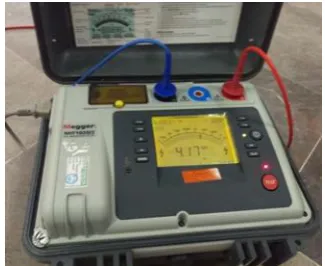
Thermal conductivity of case 2 is more than case one, but the difference is not notable. According to the results of breakdown voltage test and Ucrequation, other properties should be analyzed in order to find the reason for the breakdown voltage difference between the cases. Consequently, measuring its factors as resistivity helps solving the problem (see Fig. 10 and Table 2).
Results of the resistivity test can be used in electro-thermal equation to find breakdown voltage difference between the cases. A parallel equivalent circuit for insulation is assumed, so tan δ is equal to:
1 1
tan
RCw w
(24)
where ρ is specific resistance of material. To complete the research, the case studies samples are experimented for recognizing their dielectric constants. According to the results εr of the case 1 and case 2 are equal to 7.3 and 8, respectively. Due to the low difference between dielectric constants, their effect on the breakdown can be neglected. Furthermore, substituting ρ0 and Eq. (24)
into Eq. (22), εr eliminates from the electro-thermal
equation. Thus, combination of Eqs. (22) and (24) leads
Iranian Journal of Electrical and Electronic Engineering, Vol. 15, No. 1, March 2019 61
Fig. 10 Electric resistivity test of stress grading tubes.
Table 2 Measurement results of electric resistivity test. Voltage Time
Period [s]
Electric Resistivity of SG-Case 1
Electric Resistivity of SG-Case 2
15 191GΩ 6 TΩ
30 197 GΩ 11 TΩ
60 191 GΩ 15 TΩ
180 180 GΩ ≥ 15 TΩ
to find breakdown voltage ratio for two kinds of materials.
2
2 1 2 2
1
1 1 1
2
cr
cr
U R
U R
(25)
Using test results and Eq. (25), breakdown voltage ratio for the cases studies is:
2
1
0.67 15000 10 0.5 200
cr
cr
U U
The electro-thermal equation is used to compare voltage breakdown of the SG tubes by the formed experiments. In addition, the results prove the equation benefits in definition of effective parameters for electro-thermal breakdown. It is now clear that this ratio is close to the breakdown voltage test ratio (24/2.5 kV). Therefore, both the analytical method and the experiments have made a good benchmark to find out the insulation quality of SG. Using this method helps prevent noticeable percentage of cable termination faults.
Usually breakdown occurs in critical points and punctures cable termination from a definite point (most of punctured points are reported in triple point area [9]) and then electro-thermal breakdown extends a hole around the punctured point (Figs. 7(a) and 11). There are two kinds of thermal losses related to cable loss and insulation loss. In areas with high electric fields, insulation loss increases according to equation 2, but copper loss is constant in length of the cable. Both high electric field and boost of heat loss cause the beginning of unstable temperature alterations and hence passing the temperature limit (Tm) in triple point. Based on the
Fig. 11 Punctured cable termination in triple point area (Case 1).
test results and proofed equations, unstable heat transferring in case 1 punctures cable termination in triple point as shown in Fig.11. From Fig. 11, it can be seen that the most impact of produced thermal loss occurs on SG thickness where it has been punctured. Thus, the theoretical equations in section 2.1 have been written for transferring thermal in x direction (Fig. 6 shows the analysis for SG tube thickness). Transferring the thermal loss is in the insulation layers thickness and radial direction. According to the investigation about damaged cable termination in [9], Figs. 7(b) and 11, it can be concluded that during the main step of the breakdown, radius transferred loss has less effect in comparison to the transferred thermal energy in x direction (electro-thermal breakdown occurs in SG thickness and then a hole is extended around the punctured area). So, Eq. (22) considers the problem with a good approximation. In addition, the test in Fig. 9 simulates transferring thermal loss from the SG thickness due to the isolated samples form besides by the hot and cold electrodes of the setup.
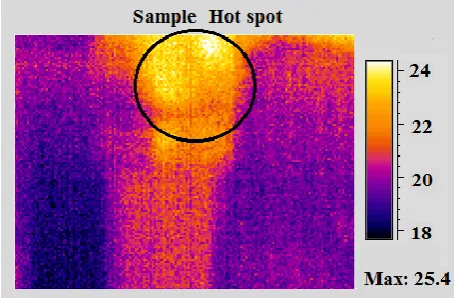
To complete the heat transferring investigation, HV tests are repeated and temperature is registered by a thermal-vision camera (Fig. 12). Table 3 illustrates the results of measured hot spots on the case studies during voltage variation. According to the result, temperature changes too slowly in case 2 which is match with the previous discussions. Furthermore, case 2 withstand higher voltages with low hot spot temperatures during the test. In contrast, temperature of case 1 changes with high slope per varying voltage. It happens due to its inefficient properties and its low resistance which causes higher current flow and thermal loss in the tube. In 3.2 kV, temperature in a definite zone of case 2 arises extremely that punctures the tube (Table 3). Based on the results, when voltage is equal to 3.2 kV, the breakdown occurs in a short time and thermal loss does
Iranian Journal of Electrical and Electronic Engineering, Vol. 15, No. 1, March 2019 62 not transfer to the other zones during the first step of the
breakdown. At the time, there is an unbalanced condition between producing and transferring thermal loss in the zone that increases temperature intensively. The test consists of varying voltage with low slopes. However, transient conditions decrease the breakdown voltage from 3.2 kV to 2.4 kV. In high frequency and transient conditions, higher frequency reduces capacitance of the tube (Zc = 1/Cωj) that causes its less effect on current flow [2].
Fig. 12 A sample of registered temperature on the case study by thermal-vision camera.
Table 3 Registered hot spots for the case studies during voltage variation (ambient temperature = 18°C)
Time [s]
Voltage of Case 1 Test [kV]
Temperatur e of Hot
Spot in Case 1 [℃]
Voltage of Case 2 Test [kV]
Temperatur e of Hot
Spot in Case 2 [℃]
120 2 33 9 24
600 2.5 38 9 27
1200 2.7 60 15 28.5
1800 3 90 15 29
2400 3.1 114 17.2 30
2500 3.2 194 17.2 31
2550 3.2 fail 17.2 31
4 Conclusion
SG material properties are an important key in cable termination aging and reducing the critical electric field. Electric conductivity of the impedance should be regulated in order to control the stress. Low electrical conductivity increases the current density in insulation, conversely, the high electrical conductivity distributes the stress to the other parts. According to the results for materials employed in terminations, electrical conductivity with coefficient of 10-10 is suitable.
In the paper, a new method is introduced to check the SG quality. Based on the electro-thermal breakdown, an equation is obtained which helps analyzing SG materials by performing a set of tests. Both thermal conductivity and dissipation factor have important roles in finding insulation quality and its breakdown voltage. An insulation with low dissipation factor, high
resistivity, high dielectric constant and proper thermal conductivity is a proper choice having upper breakdown voltage. Case 2 has the mentioned characteristics and it is the reason for having high breakdown voltage (around 24 kV). Furthermore, comparing the electrical conductivity of the two cases is possible as below.
10 2
10
σ 3.3 10
15 Ω 10 2
Case
L cm
RA T cm mm
6 1
10
σ 2.5 10
200 Ω 10 2
Case
L cm
RA G cm mm
where L and A values are equal to 10 cm and 200 mm2 respectively (for cut samples in the resistance test). Based on the discussion in the first part of conclusion, the calculated electrical conductivities show another positive point of the employed material in case 2. The method considered in this paper can be used by who wants to be sure about a production and its SG material quality.
Acknowledgment
The authors would like to thank west regional electric company of Iran for supporting the research by contract number: 2595029.
References
[1] M. Al-Muhaini and G.T. Heydt, “A novel method for evaluating future power distribution system reliability,” IEEE Transactions on Power Systems, Vol. 28, No. 3, pp. 3018–3027, 2013.
[2] A. Eigner and S. Seminon, “50 Years of electrical-stress control in cable accessories,” IEEE Electrical Insulation Magazine, Vol. 29, No. 5, pp. 47–55, 2013.
[3] F. P. Espino-Cortes, S. H. Jayaram, and E. A. Cherney, “Stress grading materials for cable terminations under fast rise time pulses,” IEEE Transactions on Dielectrics and Electrical Insulation, Vol. 13, No. 1, pp. 430-435, 2006.
[4] Y. O. Shaker, A. H. El-Hag, U. Patel and S. H. Jayaram, “Thermal modeling of medium voltage cable terminations under square pulses,” IEEE Transactions on Dielectrics and Electrical Insulation, Vol. 21, No. 3, pp. 932–939, 2014.
[5] S. Banerjee, and S. H. Jayaram, “Thermal effects of high frequency voltage on medium voltage cable termination”, in IEEE International Conference on Solid Dielectrics (ICSD),Winchester, UK, pp. 669– 672, 2007.
[6] C. H. Lee, Y. C. Lin, M. Y. Chiu, C. H. Huang, S. S. Yen and C. Haeng, “Recognition of partial discharge defects in cable terminations,” in International Conference on Condition Monitoring and Diagnosis, Beijing, China, pp. 1242–1245, 2008.
Iranian Journal of Electrical and Electronic Engineering, Vol. 15, No. 1, March 2019 63 [7] K. Uchida, H. Tanaka, and K. Hirotsu, “Study on
detection for the defects of XLPE cable lines,” IEEE Transaction On Power Delivery, Vol. 1, No. 2, pp. 663–669, 1996.
[8] M. Y. Chiu, C. H. Lee, C. H. Huang, and S. S. Yen, “The case study of on-line PD measurement on in-service MV cable terminations,” in Annual conference on IEIEJ, pp. 511–516, 2007.
[9] Z. A. A. Zarim, A. B. A. Ghani, and S. K. Tiong, “The measurement and temperature profile of cable insulation failure due to loose connection at the cable termination,” in International Symposium on Electrical Insulating Materials, pp. 570–572, 2008.
[10]V. Abbasi, “Classifying Faults Locations in Cable Terminations and Investigation of the Faults Reasons,” Iranian Journal of Electrical and Electronic Engineering, Vol. 14, No. 3, pp. 270– 277, 2018.
[11]C. H. Lee, M. Y. Chiu, C. H. Huang, S. S Yen, and K. K. Chen, “The study on diagnostics for aging trend of cable termination,” in International Conference on Condition Monitoring and Diagnosis, pp. 336–339, 2008.
[12]U. Patel, S. H. Jayaram, A. E. Hag, and R. Seetahpathy, “MV cable termination failure assessment in the context of increased use of power electronics,” in IEEE Electrical Insulation Conference, Annapolis, Maryland, USA, pp. 418– 422, 2011.
[13]E. Sharifi, S. H. Jayaram, and E. A. Cherney, “Analysis of thermal stresses in medium-voltage motor coils under repetitive fast pulse and high-frequency voltages,” IEEE Transaction on Dielectric and Electrical Insulation, Vol. 17, No. 5, pp. 1378–1384, 2010.
[14]E. Sharifi, S. Jayaram, and E. A. Cherney, “A coupled electro-thermal study of the stress grading system of medium voltage motor coils when energized by repetitive fast pulses,” in IEEE International Symposium on Electrical Insulation (ISEI), pp. 1–4, 2010.
[15]T. Bengtsson, F. Dijkhuizen, L. Ming, F. Sahlen, L. Liljestrand, D. Bormann, R. Papazyan, and M. Dahlgren, “Repetitive fast voltage stresses-causes and effects,” IEEE Electrical Insulation Magazine, Vol. 25, 4, No. 4, pp. 26–39, 2009.
[16]T. Liu, J. Fothergill, S. Dodd, and U. Nilsson, “Influence of semiconductor shields on the dielectric loss of XLPE cables,” in IEEE Conference on Electrical Insulation and Dielectric Phenomena, pp. 246–249, 2009.
[17]X. Qi, Z. Zheng, and S. Boggs, “Engineering with nonlinear dielectrics,” IEEE Electrical Insulation Magazine, Vol. 20, No. 6, pp. 27–34, 2004.
[18]T. Christen, L. Donzel, and F. Greuter, “Nonlinear resistive electric field grading part 1: Theory and simulation,” IEEE Electrical Insulation Magazine, Vol. 26, No. 6, pp. 47–59, 2010.
[19]S. Boggs, J. Densley, and J. Kuang, “Mechanism for conversion of water trees to electrical trees under impulse conditions,” IEEE Transaction on Power Delivery, Vol. 13, pp. 310–315, 1998.
[20]N. H. Malik, A. A. Al-Arainy, M. I. Qureshi, and F. R. Pazheri, “Calculation of electric field distribution at high voltage cable terminations,” in International Conference on High Voltage Engineering and Application, pp.24–27, 2010.
[21]F. P. Espino-Cortes, E.A. Cherney, and S. Jayaram, “Impact of inverter drives employing fast-switching devices on form-wound AC machine stator coil stress grading,” IEEE Electrical Insulation Magazine, Vol. 23, No. 1, pp. 16–28, 2007.
[22]L. Cabot, “Conductive carbon black selection guide for semi-conductive power cable compounds,” in International Symposium on Electrical Insulation, pp. 214–221, 2002.
[23]R. Graf, “Movie: Demonstration of stress control tubing,” Tyco Electronics Raychem, HV lab, Ottobrunn, Germany, 2005.
V. Abbasi received his B.Sc. degree in Electrical Engineering in 2002 from Shahid Chamran University, Ahvaz, Iran, and the M.Sc. and Ph.D. degrees in Electrical Engineering from the Iran University of Science and Technology (IUST), Tehran, Iran, in 2004 and 2012, respectively He is currently an Assistant Professor in Electrical Engineering Department of Kermanshah University of Technology. His current research interests include HV circuit breakers, electrical insulation, and power electronic.
S. Hemmati is currently an Assistant Professor at Kermanshah University of Technology. He received his both Ph.D. and M.Sc. in Electrical Engineering from K. N. Toosi University of Technology, Tehran, Iran in 2013 and 2008, respectively. He also earned his B.Sc. in Electrical Engineering from Bu Ali Sina University, Hamadan, Iran in 2006. In 2011, he joined as a visiting scholar to University of Wisconsin Madison, Madison, WI, USA. His research interests include design, Modeling, control, and fault diagnosis of electrical machines and finite-element analysis of electromagnetic devices.
Iranian Journal of Electrical and Electronic Engineering, Vol. 15, No. 1, March 2019 64
M. Moradi received his B.Sc. degree in Electrical Engineering from Shiraz University, Shiraz, Iran, in 2000, and the M.Sc. and Ph.D. degrees in Electrical Engineering from the Iran University of Science and Technology (IUST), Tehran, Iran in 2003 and 2011, respectively. He was with Iran Transformer Research institute (ITRI), Tehran, Iran from 2003 to 2012 as a Project Manager working in the field of transformer diagnostics, testing and life assessment. He is currently an Assistant Professor of Electrical Engineering with Razi University, Kermanshah. His research interests include power system transients, high voltage engineering, transformer diagnostics, electromagnetic compatibility, and grounding systems.
© 2019 by the authors. Licensee IUST, Tehran, Iran. This article is an open access article distributed under the terms and conditions of the Creative Commons Attribution-NonCommercial 4.0 International (CC BY-NC 4.0) license (https://creativecommons.org/licenses/by-nc/4.0/).
![Fig. 1 Equivalent circuit of cable termination (the blue part is stress grading layer) [1]](https://thumb-us.123doks.com/thumbv2/123dok_us/22665.2002466/2.595.333.513.607.730/fig-equivalent-circuit-cable-termination-stress-grading-layer.webp)
![Fig. 3 Cable with stress grading tube [22].](https://thumb-us.123doks.com/thumbv2/123dok_us/22665.2002466/3.595.54.290.84.228/fig-cable-with-stress-grading-tube.webp)