www.astesj.com 20
Smart Grid Operational functions and Control Challenges by Implementing SSSC Tailored to Optimize
performance in between Qatar and KSA on the GCC Electrical-power grid
Tariq Masood
*1, Muhammad Tajammal
2, Samer Karim Shah
3, Ghulam Hashmi
4, Suhail Aftab Qureshi
5, D. P Kothari
61Asset Integrity, Department Qatar Petroleum, Dukhan Operations, Qatar
2University of Hail, Hail, Kingdom of Saudi Arabia
3Maintenance Department, QAFAC, Doha Qatar
4Power System Engineering Department, Saudi Aramco, Dhahran, KSA
5University of Engineering and Technology, Lahore Pakistan
6J. D. College of Engineering & Management, Nagpur India
A R T I C L E I N F O A B S T R A C T
Article history:
Received: 19 August, 2017 Accepted: 06 September, 2017 Online: 30 September, 2017
This research work is novel technique to control and optimize SSSC (Subsynchronous Series Controller) functions with degree of precision in between Qatar and Kingdom of Saudi Arabia. The SSSC model developed and simulated in order to identify and determine its control and functioning parameters by introducing new tuning parameters based on that the SSSC can be adjusted stringently to witness desired results lead to address outstanding reactive power management issue. The proposed new parameters are contributing significantly to control SSSC functions in multiple directions in a power system network in between QATAR and Kingdom of Saudi Arabia at different time-based transmission contingencies on the GCC Electrical-power grid. Strategically, the SSSC capacity and capability can be utilized fully in between Qatar and Kingdom of Saudi Arabia by introducing and optimizing its control and tuning parameters more tangibly under both steady and dynamic states
Keywords: Reactive voltage Voltage regulator Power flow
1. Introduction
The SSSC has operational controllability results are clearly indicating that introduction of SSSC in between Qatar and Kingdom of Saudi Arabia power network will equitably improve the power system loadability, curtailing the losses and value-added sustainability of the power system enactment by addressing control and operational issue throughout the GCC Electrical-power grid.
Hereafter, new SSSC optimization technique can thus be magnificently expended for this type of power system process optimization. This work published in 13th the IET International
AC/DC Conference held in Manchester, February 14-16, 2017. Whereas a SSSC determines and validates the three control and effective limits which have been made-to-order at (minimum (+/-) medium (+/-(+/-), and maximum (+/-(+/-) compensation. These rheostats functioning limits are regulated by constituting their consequent PI control-values by exercising D.J. Cooper PID regulator Performance to achieve the following [1].
(1) Augmented Power flow
(2) Developed consistency & controllability (3) Augmented angle and voltage constancy.
Therefore, FACTS Controllers are convincing candidate technology options centered on that following benefits can be perceived.
ASTESJ
ISSN: 2415-6698
*Corresponding Author: Tariq Masood, Asset Integrity, Department Qatar Petroleum, Dukhan Operations, Qatar | Email: [email protected]
www.astesj.com
Special Issue on Recent Advances in Engineering Technology
Al Fadhli Inte rconnection
310 km
Bahrain 600 MW
UAE 900 MW Om an
400 MW
Ghuna n Inte rconnection
113km
Salwa Inte rconnection
290 km
Al-sila & Al-Fuhah Inte rconnection
150 km
Legends: 400kV Lines 220kV Lines
Monitoring Devices
Qat ar 750 MW
SSSC SSSC
Control function
Saudi Ara bia 120 0 MW
HVDC Back-to-Back
Kuw ait 120 0 MW
BLO CK.12 Current Meas ured 1.Al-Fua ha Substation
2.Salwa substation 3.Al-Zour S ubstaiton
4. Al-Fadhili
BLO CK.14
Reference Iq 1.Al-Fua ha Substation 2.Salwa substation 3.Al-Zour S ubstaiton
4. Al-Fadhili
RTU Remote Telemetry Unit
BLO CK.13
Reference Volta ge 1.Al-Fua ha Substation
1.0pu (220KV) 2.Salwa substation 3.Al-Zour S ubstaiton 4. Al-Fadhili 1.0PU (400KV)
BLO CK.15 Final Control Block: VD1 (Voltage Deviation) VD2 (Voltage Deviation) VD3 (Voltage Deviation) ID1 (current De via tion) ID2 (current De via tion) ID3 (current De via tion) BLO CK.11
Voltage Meas ured 1.Al-Fua ha 1.0pu (220KV)
2.Salwa substation 3.Al-Zour S ubstaiton 4. Al-Fadhili 1.0PU
(400KV)
Kuw ait
120 0MW
400kV KSA
120 0MW
400kV Bahrain
600MW
400kV Qat ar
750MW
400kV
Om an
400MW
220kV UAE
900MW
400kV
Calculated mea n-Value
RTU Remote Telemetry
Unit
Control Block 1, 2, 3, 4, input s ignals and from the field and corresponding calculat ed deviations communica ted through Control Block 5 & 6
RTU Remote Telemetry Unit
BLO CK.16 Final Control Block: Voltage deviation from
+/-+/-2% to +/-6% Power dev iat ion from +/-2% to +/- 6%
Control function
Main Central Control Room (MCCR) Parallel Control Signal to SSSC
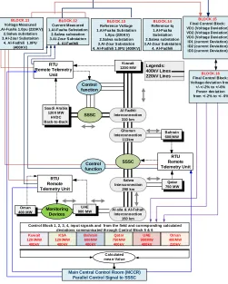
Figure 1. SSSC structure in between Qatar and Kingdom of Saudi Arabia
Figure 1 shows the GCC power network by retaining SSSC at augmented whereabouts by exercising Wideband-Delphi-Technique.
Model reveals how much notional concentrated power can be dispensed in between QATAR and Kingdom of Saudi Arabia.
At maximum conjectural power, what is borderline voltage
Model reveals how much reactance must be retained by the orthodox series capacitance to double the power conveyance in between Qatar and Kingdom of Saudi Arabia if vital and prerequisite.
Compute the introduced voltage by the series capacitor in between QATAR and Kingdom of Saudi Arabia
By SSSC how much introduced and instilled/injected reactive voltage Vr is upheld at diverse compensation of SSSC in between Qatar and Kingdom of Saudi Arabia and Compute the determined power supplied at persistent introduced voltage Vr
If the load angle decreases from 71 to 0 how much power will be produced by SSSC in between Qatar and Kingdom of Saudi Arabia.
2. GCC Electrical-power grid background
The GCC power-grid is constituted and employed into eight premeditated power system operational directions in order to meet national and industrial customers necessities in a consistent and viable demeanors at the GCC Electrical-power grid-network as shown in Figure 1 as considered and described with facts and figures, this is also published in [1] .
3. SSSC Operational Analyses
Principally, the SSSC-series counterbalance device location is not very much perilous it can be employed anyplace on the GCC Electrical-power grid. In this case the SSSC has been retained at the borderline to decrease the power-line transmission impedance unnaturally by SSSC which is controlling to upsurge the power flow in the power transmission system in (5) and (6) determine how much line impedance (XC) has been Controlled and Managed after employing series but stable capacitor’s Kseries factor.
SSSC encompasses of capacitors and reactors to diverge the power-line impedance on domineering need basis vigorously. Predominantly, the SSSC injects the voltage in a series into the power transmission network at the midpoint of Kingdom of Saudi Arabia and Qatar whereas instilled/injected the voltage at midpoint Vr has been computed in (7). The SSSC stipulates or expends reactive-power in capacitive/inductive control-mode of functions on the GCC power-grid, wherein the SSSC instilled/injected voltage in phase quadrature with the line current of the power network.
Figure 2 denotes maroon trend in the graphical presentation of the SSSC processes in capacitive and inductive mode of functions. Practically, blue trends denote how much real power transferred can transferred when electrical-power transmission network compensation carried-out capacitive, inductive mode of operations or neutral without any compensation factor. Figure 3 signifies that a SSSC has a main and great influence on power steadiness and load flow, but ithas limited impact on voltage profile enhancement as exhibited in (28) that Vm, Vs, Vr has negligible or no effect with SSSC [2].
0
π
0 δ (rad)
1
R
ea
l P
ow
e
r
(pu
)
Capacitive
Uncompensated
Inductive
Figure 2. Signify the compensation factor by SSSC [2]
3.1.By employing Series Fixed Capacitor to upsurge the Power on the GCC Electrical-power grid
Herein determined conjectural power can be dispensed and distributed without conservative or non-conventional series compensation, the voltage structured transitorily but not vigorously and unvaryingly which is outfitted at 800 km long electrical-power transmission network from Kingdom of Saudi Arabia to Qatar or vice versa along with its attendant substations. Now if series capacitor is connected at midpoint voltage as stated in Figure 3 to resource and expend sufficient reactive power to counterbalance as prerequisite. Equation (5) expended to compute series compensation factor to convalesce the power system steadiness and double the power at power transmission lines reactance XC= 136.626 Ohms as intended in (6) and (7) [3]. 𝐾𝑠𝑒𝑟𝑖𝑒𝑠=
𝑋𝑐 2 × 𝑍𝑎
𝑐𝑜𝑠𝜃
2 (5)
𝑋𝑐= 2 × 𝐾𝑠𝑒𝑟𝑖𝑒𝑠× 𝑍𝑎𝑡𝑎𝑛 𝜃
2= 136.626 𝑂ℎ𝑚𝑠 (6)
𝑃𝑚𝑎𝑥=
𝑉2
𝑍𝑎− 𝑋𝐶× 𝑆𝑖𝑛(43.26°)
= 1223 𝑀𝑊 (7)
Equation (7) reveals the concentrated power by adapting power transmission line reactance by series capacitor Units.
3.2.By implementing Series-Capacitor to upsurge the Power on
the GCC Electrical-power grid
The SSSC has a tremendous competence to upturn the electrical Power flow and improve dynamic steadiness to supplant usual and uneconomical fixed series capacitors are expended to govern the prerequisite reactive current at midpoint in between Qatar and Kingdom of Saudi Arabia for recompense [4].
Instill/Injected current with series capacitor is computed by exercising in (8), (9).
𝐼𝑚=
𝑉𝑠𝑖𝑛𝛿2
(1 − 𝐾𝑠𝑒𝑟𝑖𝑒𝑠)𝑍𝑎𝑠𝑖𝑛𝜃2
= 2.1159𝑝𝑢 (8)
Instilled/injected voltage as given below 𝑉̂𝑟= 1.5237 × 𝑡𝑎𝑛
𝜃
2= 0.8881𝑝𝑢 (9)
Equation (9) reveals the in a Phase injected/instill voltage 𝑉𝑟= 𝑉̂𝑟×
𝑉
√3= 205.03 𝑘𝑉 (10)
Equation (10) reveals the instilled/injected voltage in between QATAR and Kingdom of Saudi Arabia. Herein determined power flow can be sustained with unremitting voltage inserted by the SSSC at midpoint. Firstly, the SIL computed and determined by using Equation (11)
𝑃̂ = 𝑃 𝑃𝑛
= 𝐴𝑐𝑜𝑠𝛿 + 𝐵𝑠𝑖𝑛𝛿
2 (11)
amount of real power can be dispensed in line with Pn, this is identified as a SIL in contradiction of the real electrical-power delivery.
Where
𝐴 = 1
𝑠𝑖𝑛𝜃= 1.40115 ; 𝐵 = 𝑉̂𝑟
2𝑠𝑖𝑛𝜃2
= 1.14735 (12)
Equation (13) reveals electrical Power flow with unremitting reactive voltage instilled/injected whereas the 𝑃̂ is determined when 𝑑𝑃̂
𝑑𝛿= 0
𝑑𝑃̂
𝑑𝛿= 𝐴𝑐𝑜𝑠𝛿 − 𝐵𝑠𝑖𝑛 𝛿
2 (13)
Equation (14) resultant after substituting 𝑑𝑃̂
𝑑𝛿= 0 value 0 = 𝐴𝑐𝑜𝑠𝛿 − 𝐵𝑠𝑖𝑛𝛿
2 (14)
Unassumingly 𝑐𝑜𝑠𝛿 and 𝑠𝑖𝑛𝛿 are factorized as resultant in (15) 𝑐𝑜𝑠𝛿 = 𝑐𝑜𝑠 (𝛿
2+ 𝛿
2) ; 𝑠𝑖𝑛𝛿 = 𝑠𝑖𝑛 ( 𝛿 2+
𝛿
2) (15)
Where
cos(𝐴 + 𝐵) = 𝐶𝑜𝑠𝐴. 𝐶𝑜𝑠𝐵 − 𝑆𝑖𝑛𝐴. 𝑆𝑖𝑛𝐵 (16)
Equation (17) resultant after replacing 𝑐𝑜𝑠𝛿 and 𝑠𝑖𝑛𝛿 values in (16)
𝑐𝑜𝑠 (𝛿 2+
𝛿 2) = 𝑐𝑜𝑠
𝛿 2. 𝑐𝑜𝑠
𝛿 2− 𝑠𝑖𝑛
𝛿 2. 𝑠𝑖𝑛
𝛿
2 (17)
Equation (17) is the streamlined and resultant in (18) 𝑐𝑜𝑠𝛿 = 𝑐𝑜𝑠2𝛿
2− 𝑠𝑖𝑛 2𝛿
2 (18)
Equation (18) 𝑐𝑜𝑠𝛿 value subtract in (14) and resultant from (19) 0 = 𝐴 (𝑐𝑜𝑠2𝛿
2− 𝑠𝑖𝑛 2𝛿
2) − 𝐵𝑠𝑖𝑛 𝛿
2 (19)
Whereas 𝑐𝑜𝑠2𝛿
2= (1 − 𝑠𝑖𝑛 2𝛿
2) (20)
Equation (20) 𝑐𝑜𝑠2 𝛿
2 subtracted in (19) and developed new (21) 0= 𝐴 ((1 − 𝑠𝑖𝑛2 𝛿
2) − 𝑠𝑖𝑛 2 𝛿
2) − 𝐵𝑠𝑖𝑛 𝛿
2 (21)
𝐴(1 − 𝑥2− 𝑥2) − 𝐵𝑥 = 0 (22)
−2𝐴𝑥2+ 𝐴 − 𝐵𝑥 = 0 (23)
−(2𝐴𝑥2− 𝐴 + 𝐵𝑥) = 0 (24)
2𝐴𝑥2+ 𝐵𝑥 − 𝐴 = 0 (25)
Equation resultant from (25) to convert into Quadratic form. ∫(𝑥) = (𝑥 + 𝑏 2𝑎) 2 +4𝑎𝑐 − 𝑏 2 4𝑎 (26)
Equation (26) expressed the Quadratic function as detailed below with factors. (𝑥 + 𝐵 4𝐴) 2 +(4 × 2𝐴 × −𝐴) − 𝐵 2 4𝐴 = 0 (27)
(𝑥 + 𝐵 4𝐴) 2 −8𝐴 2+ 𝐵2 4𝐴 = 0 (28)
Equation (27) and (28) Quadratic roles are defined and extracted and resultant in (29) 𝑥 = − 𝐵 4𝐴± √8𝐴2+ 𝐵2 4𝐴 (29)
Equation (29) subtracted A and B factors values as defined and calculated in (12) and resultant in new (30) 𝑥 = − 1.401 4 × 1.4735± √8 × 1.47352+ 1.4012 4 × 1.4735 (30)
Finally, the “x” values are signified as given below: 𝑥 = 0.5314 = 𝑠𝑖𝑛𝛿 2=→ 𝛿 = 64.2° (31)
Equation (31) reveals the 𝑥 = 0.5314 and electrical power angle resultant Where 𝑃̂𝑚𝑎𝑥 = 𝐴𝑠𝑖𝑛𝛿 + 𝐵𝑐𝑜𝑠𝜃 (32)
𝑃̂𝑚𝑎𝑥= 𝐴𝑠𝑖𝑛(64.2°) + 𝐵𝑐𝑜𝑠(45.5°)𝑃̂𝑚𝑎𝑥 = 2.06519 (33)
Equation (32) subtract the A, B, ∅ 𝑎𝑛𝑑 𝛿 values and resultant the 𝑃̂𝑚𝑎𝑥 value. 𝑃𝑚𝑎𝑥= 𝑃̂𝑚𝑎𝑥× 4002 316.228= 1044.9 𝑀𝑊 (34)
Equation (34) signifies the concentrated electrical power dispensed and distributed in the GCC Electrical-power grid by retaining SSSC to uphold persistent Vr vigorously in the Midpoint of QATAR and Kingdom of Saudi Arabia as illustrated in Figure 4 [5]. 1 2 Generator - + L1 R iLQ + -Lr Rr L2 Infinite bus SSSC Figure 4: SSSC connected in between Qatar and Kingdom of Saudi Arabia IS IR VS VR X VQ Vm Figure 5: SSSC connected in between Qatar and Kingdom of Saudi Arabia VS VR Reference 15º 30º 75º Vq Vm VQR VQL Figure 6. Phasor diagram of voltage profile VS VR VQ IS Reference VQR VQL Figure 7. SSSC connected at the midpoint and instilled/injected VQ toward VR Figure 5: signifies that counterbalance device employed in the middle of the of the power transmission line, this is voltage source only dispense reactive electrical power not a real power. Figure 6 displays the influence of location if counterbalance device employment on voltage profile, the voltage on left side of the counterbalance device would be VQL and right side VQR. Figure 7 illustrates that the series counterbalance device employed in the middle the worst voltage-profile occurred at each side of the counterbalance device, whereas the voltage-profile vector aligns with the current vector [5]. Therefore, the midpoint voltage-profile is the same with/without SSSC functions as exhibited in (37) and (38) SSSC power flow with 𝛿 = 0[6]. 𝑃𝑚𝑎𝑥= 1.147 × 4002 316.2= 580𝑀𝑊 𝑉̂𝑚= 𝑐𝑜𝑠𝛿2 𝑐𝑜𝑠𝜃2 𝛿 = 0 (35)
𝑉̂𝑚= 1
𝑐𝑜𝑠 × 22.76°= 1.1 𝑝𝑢 (36)
Equation (35) reveals the midpoint voltage if 𝛿 = 0 therefore, 𝑉𝑠𝑎𝑛𝑑 𝑉𝑅 voltage-profile are computed in (37) and (38). Sending end from the Kingdom of Saudi Arabia and receiving end at QATAR
𝑉𝑠 = 𝑉𝑚∠0 − 𝑗 𝑉𝑟
2 = 1.171∠0 − 𝑗 0.8881
2 (37)
𝑉𝑅 = 𝑉𝑚∠0 + 𝑗 𝑉𝑟
2 = 1.171∠0 − 𝑗 0.8881
2 (38)
3.3.SSSC input Data
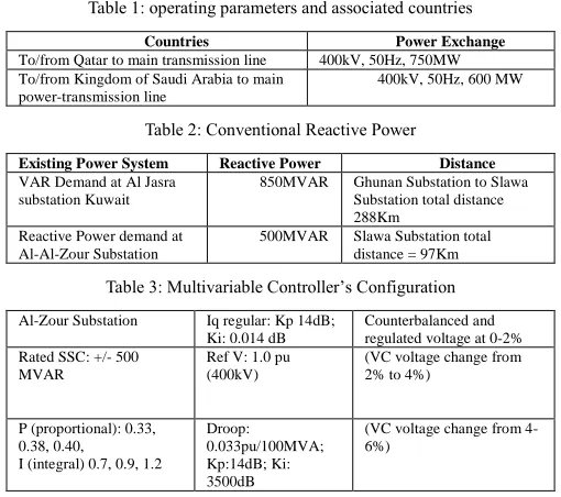
Table 1: operating parameters and associated countries
Countries Power Exchange
To/from Qatar to main transmission line 400kV, 50Hz, 750MW
To/from Kingdom of Saudi Arabia to main power-transmission line
400kV, 50Hz, 600 MW
Table 2: Conventional Reactive Power
Existing Power System Reactive Power Distance
VAR Demand at Al Jasra substation Kuwait
850MVAR Ghunan Substation to Slawa
Substation total distance 288Km
Reactive Power demand at Al-Al-Zour Substation
500MVAR Slawa Substation total
distance = 97Km
Table 3: Multivariable Controller’s Configuration
Al-Zour Substation Iq regular: Kp 14dB;
Ki: 0.014 dB
Counterbalanced and regulated voltage at 0-2% Rated SSC: +/- 500
MVAR
Ref V: 1.0 pu (400kV)
(VC voltage change from 2% to 4%)
P (proportional): 0.33, 0.38, 0.40,
I (integral) 0.7, 0.9, 1.2
Droop:
0.033pu/100MVA; Kp:14dB; Ki: 3500dB
(VC voltage change from 4-6%)
4. Results and Discussion
4.1.Maximum level Vr voltage-injection
It has been simulated and authenticated that further real power can be up-surged in the power transmission line to touch its design specification by up-surging the SSSC compensation factor from 50% to 65% reactive voltage instilled/injected voltage would be 0.8864pu which is equivalent to 204kV and current Im = 2.1pu and 𝜹 = 𝟔𝟑. 𝟖𝟕° will activate consequently at different functioning condition total 1200MW power will be produced and distributed on the GCC electrical-Electrical-power grid. This is known as a determined compensation by implementing a SSSC and its compensation factor from 50% to 65% to obtained projected power produced and delivered in the electrical power transmission network on the GCC electrical-Electrical-power grid.
4.2.Medium level Vr voltage-injection
As simulated by Matlab/SIMULINK and scientific/ mathematical model Vr instilled/injected voltage 0.5936pu which is uniform and match to 137kV at 50% SSSC reactive voltage compensation whereas the midpoint current Im = 1.4459pu, and 𝜹 = 𝟕𝟏. 𝟑𝟐° will activate consequently in this functioning circumstance to a total 1079 MW power which can be produced
and distributed on the GCC Electrical-power grid as validated by the results. Infact, QATAR and Kingdom of Saudi Arabia system has been devised to produce and distribute concentrated 1200MW electrical-power in the GCC Electrical-power grid during a peak load, therefore Margin is obtainable to upsurge the power up to its projected specification. This is also identified as a medium compensation by a SSSC compensation factor from 20% to 50%. Therefore, the Control function block expended to readjust PI controller response as exhibited in Figure 10 to diverge the firing angle of the Thyrister control [7].
4.3.Minimum level Vr voltage-Injection
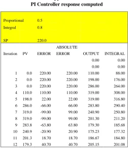
In the third challenge of operations, further this model was simulated and authenticated by exercising SSSC Controller. At minimum compensation of the SSSC compensation real power reduce considerably in the power transmission line to touch its projected specification by decreasing the SSSC compensation factor from 5% to 20% reactive voltage instilled/injected voltage would be 0.3710pu which is equal to 86.67kV and current Im = 0.974pu and 𝜹 = 𝟕𝟕. 𝟓𝟕° will activate consequently in this functioning condition total 986MW power will be produced and distributed on the GCC Electrical-power grid. This is identified as a minutest compensation by using a SSSC Controller and its compensation factor from 5 to 20% to achieve projected electrical power delivery of transmission network on the GCC Electrical-power grid. As instilled/injected voltage up-surged based on compensation from 5% to 20% there is considerable power flow and steadiness enhancement but very insignificant influence on voltage-profile as verified simulated consequences in Figure 8 (a) reactive power injection-waveform 8(b) indicates the total power delivered in between Qatar and Kingdom of Saudi Arabia, this is also computed in equation (34). The PI controller configured and demonstrated its operational response in Figure 9. Detailed configuration discussed as given in the appendices [8].
Figure 8 (a). Reactive power injection on the GCC Power Grid
Figure 10. demonstrates the PI controller parameters
5. Conclusion
Fundamental creativity of the SSSC application in the GCC Electrical-power grid transmission line compensation is the subject of extensive significance. In this study, it has been computed and simulated how much maximum power can be produced and distributed in between QATAR and Kingdom of Saudi Arabia without any process vagueness. It has been reasonable how much reactance must be provided by the series capacitance to double the power supply in between Qatar and Kingdom of Saudi Arabia. It also has been also identified and unwavering amount of reactive voltage to be instilled/injected in between Qatar and Kingdom of Saudi Arabia in order to provide concentrated power delivery on the GCC Electrical-Power grid.
If the load angle as decreased below from 65 to 0 amount of electrical-power will be produced by SSSC in between Qatar and Kingdom of Saudi Arabia. Herein, the GCC electrical-power network will exclusively upsurge the power system loadability, decrease the losses and improve sustainability of the electrical-power system functioning. The results also illustrates that SSSC is multipurpose equipment with stupendous active capability to improve power system stability margin on the GCC Electrical-power grid. Based on these results, SSSC is a very strong-candidate to be instigated at GCC Electrical-power grid. It also demonstrates optimistic influence on neighboring countries’ power system functions at the GCC Electrical-power grid.
Table 4 Terms and Abbreviations
Name Abbreviations
GCC Gulf Cooperative Council Ir Reactive current Za Line Impedance Vm Midpoint voltage
Kshunt series compensation factor in the network Pn Surge Impedance
KSA Kingdom of Saudi Arabia
Conflict of Interest
No conflict of interest in this paper has been identified.
Acknowledgment
I extend my special gratitude to all my coauthors in this paper in particularly late Prof. Dr Abdel-ETY Edris (Icon of FACTS
Technology) at Santa Clara University for their unprecedented support and exceptional contribution to make this study a great success. I am also very grateful to my little Doll Princesses Fatima Masood, who kept me busy full time not giving me space during my research on smart control
References.
[1] Tariq Masood, R.K. Aggarwal, S.A. Qureshi “Novel Control of a SSSC Connecting the Oman and United Arab Emirates in the GCC power Grid Interconnection” published in IJAPE International Journal of Automation and Power Engineering, Volume 2, issue 1 January, 2013.
[2] Tariq Masood, Abdel Aty Edris, Suahil Aftab Qureshi, Muhammad Tajammal, Murtaza Hashmi DP Kothari, Samer Kareem “SSSC tailored to optimization performance in Between United Arab Emirates and Oman on the GCC Power Grid” published on 14-16 February, 2017 in the 13th IET International Conference on AC and DC power Transmission Conference. [3] Mohammed Rasetgar, Mehdi Saradarzeda “An Improved D-SSSC Voltage
and Current Load Balancing Control Strategy Under Unbalanced Load published in 25th Iranian IEEE ICEE 2017.
[4] Mohammed Abdul, Mohd Akram, “Power System Stability Enhancement using Static Synchronous Series Compensator” Published in IEEE (SCOPES)-2016
[5] S. Jamali, A. Kazemi, H. Shateri “Voltage Inversion due to Presence of SSSC on Adjacent Lines and Distance Relay Mal-Operation” published in 2008 IEEE Conference.
[6] D. Rai, S.O. Faried, “Impact of Imbalanced Phase Operation of SSSC on Damping Subsynchronous Resonance published in 2011 IEEE Conference,
[7] Tariq Masood “Improvement of Voltage and power flow control in the GCC Electrical-power grid by using coordinated FACTS Controllers” Ph.D Thesis, published in 2013 at University of Bath, UK.
[8] Tariq Masood, R.K. Aggarwal, Nasser Al-Eamdi “Enhanced Power Flow/Voltage Control in the GCC Grid by SSSC (SUBSYNCHRONOUS SERIES CONTROLLER) Robustness” published by Lambert in 2013 ISBN: 978-3-659-40995-0.
Appendix No.1
PI Controller response computed
Proportional 0.5
Integral 0.8
SP 220.0
ABSOLUTE
Iteration PV ERROR ERROR OUTPUT INTEGRAL
0.00 0.00
0.00 0.00
1 0.0 220.00 220.00 110.00 88.00
2 0.0 220.00 220.00 198.00 176.00
3 0.0 220.00 220.00 286.00 264.00
4 110.0 110.00 110.00 319.00 308.00
5 198.0 22.00 22.00 319.00 316.80
6 286.0 -66.00 66.00 283.80 290.40
7 319.0 -99.00 99.00 240.90 250.80
8 319.0 -99.00 99.00 201.30 211.20
9 283.8 -63.80 63.80 179.30 185.68
10 240.9 -20.90 20.90 175.23 177.32
11 201.3 18.70 18.70 186.67 184.80
12 179.3 40.70 40.70 205.15 201.08
0 50 100 150 200 250 300 350 400 450
1 3 5 7 9 11 13 15 17 19 21 23 25 27 29 31 33 35 37 39 41 43 45 47 49
CONT
ROL
L
E
R
OUT
P
UT
CONTROLLER ITERATION
DEADTIME = 2, PROPORTIONAL=0.5
I=.6 I=.8
I=.9 I=1
13 175.2 44.77 44.77 223.47 218.99
14 186.7 33.33 33.33 235.65 232.32
15 205.2 14.85 14.85 239.75 238.26
16 223.5 -3.46 3.46 236.53 236.87
17 235.7 -15.65 15.65 229.05 230.61
18 239.7 -19.75 19.75 220.74 222.71
19 236.5 -16.53 16.53 214.45 216.10
20 229.0 -9.05 9.05 211.58 212.48
21 220.7 -0.74 0.74 212.11 212.19
22 214.5 5.55 5.55 214.96 214.41
23 211.6 8.42 8.42 218.62 217.78
24 212.1 7.89 7.89 221.72 220.93
25 215.0 5.04 5.04 223.45 222.95
26 218.6 1.38 1.38 223.64 223.50
27 221.7 -1.72 1.72 222.64 222.81
28 223.4 -3.45 3.45 221.09 221.43
29 223.6 -3.64 3.64 219.61 219.98
30 222.6 -2.64 2.64 218.66 218.92
31 221.1 -1.09 1.09 218.38 218.49
32 219.6 0.39 0.39 218.68 218.64
33 218.7 1.34 1.34 219.31 219.18
34 218.4 1.62 1.62 219.99 219.83
35 218.7 1.32 1.32 220.49 220.36
36 219.3 0.69 0.69 220.70 220.63
37 220.0 0.01 0.01 220.64 220.63
38 220.5 -0.49 0.49 220.39 220.44
39 220.7 -0.70 0.70 220.09 220.16
40 220.6 -0.64 0.64 219.84 219.91
41 220.4 -0.39 0.39 219.71 219.75
42 220.1 -0.09 0.09 219.70 219.71
43 219.8 0.16 0.16 219.79 219.78
44 219.7 0.29 0.29 219.92 219.89
45 219.7 0.30 0.30 220.04 220.01
46 219.8 0.21 0.21 220.11 220.09
47 219.9 0.08 0.08 220.13 220.13
48 220.0 -0.04 0.04 220.11 220.11
49 220.1 -0.11 0.11 220.05 220.06
50 220.1 -0.13 0.13 220.00 220.01
Appendix No. 2
SSSC Controller configuration
275KV United Arab Emirates P owe r
Distribu tion Network (6 Circuits)
220 KV 50HZ 1 X 125MVAR 52 KM
OLTC Onl ine tap chang er tran sformers
220KV 50HZ 1 X 125MVAR
220 KV Oman Power Distribu tio n
Networ k
Proposed SSSC controller to be installed in between Qatar and Kingdom Saudi Arabia
Loc ation No.3 SSS C input data:
United Arab Emirates to Oman = 400 MW Voltage an d frequ ency = 220KV and 50HZ Reactive Power Demand at UAE Side = 125 MVAR Reactive Power Demand at Oman Si de = 125 MVAR United Arab Emirates P owe r d ema nd= 900 MW Voltage an d frequ ency = 400KV, 50 HZ
Dis tance:
Al-Salwa substa tion (Qatar) to A l-Sila substa tio n (UAE) =150 KM Al Fuhah substation (UAE) to A l-Wasse t Substatio n (Oman) = 50 KM
UPFC configura tion:
Converter No.1 = SSS C ( Ser ies connection Al-Fuhah Sub station UA E) SSS C = +/- 250MVAR
Integrated PID Controller’s input data:
P = 0.42 and .32 I = 0.6, 0.8, 0.9, 1.0, 1.1 D = non e
Reactive Power Compensation codes are derive d in both Mode operations :
CC2 and LC2 = minimum compen sa tion capacitive or ind uctive (VC voltage change from 1 to 5%)
CC22 and LC22 = medium co mp ensati on cap acitive or i nductive(VC voltage change from 5% to 10%)
CC222 and LC222 = full compe nsa tion capacitive o r ind uctive(VC voltage chang e grea ter than 10%)
66KV Oman Power Distribu tion Network
SSSC control system Pole
control Pole control
Pole control
Pole control
Pole control
Pole control
Pole control
Pole control
Signal f rom CT Signal f rom PT Converter
No.2
Voltage magnitude Calculator
Polarit y detector
Error amplifier (PI Cont roller)
Vq Ref + +
V
-Phase shift er +/- 90 deg
Phase locked loop
+
Converter gate pattern logic Al Sila
Sub station
From S alwa S ubstation Qa tar
400KV 50HZ 2 X 125MVAR
Al-Fuhah Sub station
Appendix No. 3
SSSC Centralized and Decentralized Control
Decentralized controller configuration and implementation to control and monitor individual FACTS device
operations at GCC Power Grid
Location Controller’s input data
UPFC configura tion:
Converter No.1 = STATCOM (shunt conn ection at Kingdo m Sau di A rabia side) Converter No.2 = SSS C ( Ser ies connection Kuwait side)
STATCOM = 250 MVAR SSS C = 250 MVAR RATED UPFC = +/- 500 MVAR
Location in betwe en Al-Zour (Kuwait) and Al-Fadhil substa tion KS A Droop =0.45/100VA
STATCOMconfigura tion:
STATCOM (shunt conn ected at S alwa sub station in between Bah rain and Doha) RATED STATCOM = +/- 500 MVAR
Droop =0.37/100VA
SSS C configura tion:
Converter No.1 = SSS C ( Ser ies connection Al-Fuhah Sub station UA E) SSS C = +/- 250MVAR
Integrated PID Controller’s input data:
P = 0.42 and .32 I = 0.6, 0.8, 0.9, 1.0, 1.1
Positive sequence fundamental line voltage calculator
Slope sett ing K Slope K1 -K2/S
Instantaneous reactive
current calculator
Error amplifier (PI Cont roller)
Vref + iqRef +
+
iq -V
-UPFC control system Pole
control Pole control
Pole control
Pole control
Pole control
Pole control
Pole control
Pole control
Phase Lock loop Voltage
magnitude Calculator
Polarit y detector
Error amplifier (PI Cont roller)
Vq Ref + +
V
-Phase shift er +/- 90 deg
Phase locked loop
+
SSSC Converter gate
pattern logic
STATCOM Converter gate
pattern logic Positive
sequence fundamental line voltage calculator
Slope sett ing K Slope K1 -K2/S
Instantaneous reactive
current calculator
Error amplifier (PI Cont roller)
Vref + iqRef +
+
iq -V
-Phase Lock loop Voltage
magnitude Calculator
Polarit y detector
Error amplifier (PI Cont roller)
Vq Ref + +
V
-Phase shift er +/- 90 deg
Phase locked loop
+
SSSC Converter gate
pattern logic
STATCOM Converter gate
pattern logic
CT VT
Salwas substation (Qatar)
Al-Zour substati on (Kuwai t)
CT VT
Al-Fadhil i Substation (KSA)
CT VT
CT VT
Al-Fuhah Substation (UAE)
STATCOM control system Pole
control Pole control
Pole control
Pole control
Pole control
Pole control
Pole control
Pole control SSSC control
system Pole
control Pole control
Pole control
Pole control
Pole control
Pole control
Pole control