1.
Introduction
Greenhouse emissions from various industrial settings need to be reduced to curb global warming. Energy-efficient industrial settings have been designed to keep global warming at an acceptable level. In this context, many researchers [1–3] have focused their attention on optimizing the geometry of engineering equipment with the hope of attaining higher thermal efficiency. The performance and compactness of this equipment can be achieved by using nanofluids instead of conventional fluids, such as water, oil, ethylene glycol, and so on. Studies on fluid flow and heat transfer had been carried out by various researchers [4-7] by adding millimeter- or
micrometer-sized particles into the fluid. These suspended particles are relatively larger in size as compared to nanoparticles and therefore, they have poor suspension stability, clog channels, and are abrasive. Thus, fluids with larger-sized particles have been discarded for engineering applications. However, fluids with nanometer-sized particles do not suffer from these problems and have higher thermal conductivity than the theoretical predictions [8]. The heat transfer enhancement with nanofluids has been studied comprehensively by Xuian and Li [9], Wang and Majumdar [10], and Kakac and Pramuanjaroenkij [11]. Heat transfer with nanofluids is augmented because the surface area, heat capacity, and thermal conductivity of nanofluids have been increased. Moreover, they demonstrated that
inter-Fluid flow and heat transfer characteristics in a curved rectangular duct
using an Al
2O
3-water nanofluid
Ashok K. Barik*, Binodini Nayak
Department of Mechanical Engineering, College of Engineering and Technology, Bhubaneswar -751029, Odisha, India Journal of Heat and Mass Transfer Research 4 (2016) 103-115
Journal of Heat and Mass Transfer Research
Journal homepage: http://jhmtr.journals.semnan.ac.ir
A B S T R A C T
In the present research, the laminar forced convective heat transfer and fluid flow characteristics of an Al2O3-water nanofluid flowing in different pipe bends (i.e., 180°
and 90°) have been numerically investigated in a three-dimensional computational domain using the finite volume technique. The effects of different pertinent parameters, such as the Reynolds number of the duct, volume fraction of the nanoparticles, diameter of the nanoparticles, aspect ratio of the duct, and the duct bend angle on the hydrodynamic and thermal characteristics of the flow have been presented. It was observed that heat transfer is augmented by replacing conventional fluid with an Al2O3-water nanofluid. The nanoparticle volume fraction was found to be
an important parameter to increase the heat transfer in a pipe bend. It was also observed that the thermo-hydraulic characteristics of the flow changes with the duct aspect ratio, and the heat transfer rate improves with changes in the aspect ratio. The heat transfer in a pipe with a 180° bend was obtained to be higher than in a pipe with a 90° bend at particular values of the volume fraction and Reynolds number. Moreover, the present study computed Nusselt number for a pipe with a 180° bend and a rectangular cross section was validated with the existing literature.
© 2017 Published by Semnan University Press. All rights reserved. DOI: 10.22075/jhmtr.2017.1503.1100
PAPER INFO
History:
Submitted 2016-10-22 Revised 2017-06-28 Accepted 2017-07-22
Keywords:
Nanofluid; Forced convection; 180° return-bend pipe; Aspect ratio
Corresponding Author : Department of Mechanical Engineering, College of Engineering and Technology, Bhubaneswar-751029, Odisha, India
particle collisions and mixing are intensified due to the suspension of nanoparticles in the fluid. The convective heat transfer of CuO-water and Al2O3
-water in a circular tube with a constant wall temperature was studied by Heris et al. [12, 13] to demonstrate the higher heat transfer capability of nanofluids compared to conventional fluids. An experimental study on convective heat transfer in the developing region of circular tubes was carried out by Anoop et al. [14] using two different sizes of Al2O3 nanoparticles (150 nm and 45 nm). The
convective heat transfer coefficient was higher with smaller (45 nm) nanoparticles than with larger nanoparticles. Similar observations were reported by Nguyen et al. [15]. The effect of temperature on the thermal conductivity of nanofluids was investigated by Das et al. [16]. They reported that the well-known theoretical models such as the Maxwell [17] and Hamilton–Crosser models [18] under-predicts the thermal conductivity of nanofluids.
In recent years, the focus has been shifted to carrying out studies on the thermo-hydraulic performances of nanofluids using different computational approaches (i.e., single-phase, two-phase, and lattice Boltzmann methods). The entropy generation for Al2O3-water and TiO2-water
nanofluids flowing in a circular tube subjected to constant temperature was studied numerically by Leong et al. [19]. They reported that the entropy generation is reduced by 10.8% for the Al2O3-water
nanofluid as compared to the base fluid when its volume fraction was maintained at 7%. The effect of the volume fraction of Al2O3 particles and their
diameter on entropy generation was studied numerically using the finite volume method by Tabrizi and Seyfl [20]. The heat transfer enhancement for micro-pin-fin heat sinks (MPFHS) using an Al2O3-water nanofluid was carried out
numerically by Seyfl and Feizbakshi [21] with the single-phase approach. A similar approach was considered by Nazififard et al. [22] to study the turbulent heat transfer characteristics in a sub-channel using an alumina-water nanofluid. Bianco et al. [23] numerically studied the forced convection heat transfer of a developing laminar flow in a straight circular tube. They showed that the heat transfer enhancement was a strong function of the volume concentration of an Al2O3-water nanofluid.
However, the wall shear stress also increased with the nanofluid concentration.
The heat transfer performance of Al2O3 and CuO
nanofluids in the flat tubes of an automobile radiator was studied numerically by Vajjha et al. [24]. They observed a significant percentage increase (i.e., 94%) in the heat transfer coefficient over the base fluid when 10% Al2O3 was added to water. A numerical
study on horizontally curved tubes employing Al2O3
-water nanofluid was carried out by Akbarinia and Behzadmehr [25] to investigate the relative effects of buoyancy and centrifugal forces on the hydrodynamic parameters. At a higher Grashof number, two non-symmetric secondary vortices were found in the vertical plane, and these vortices were moved downward because of the higher buoyancy force in the vertical plane. Recently, a numerical simulation was carried out by Choi and Zhang [26] in a pipe with a return bend that carried an Al2O3
nanofluid. The average Nusselt number in the curved portion was observed to be higher than at the inlet and outlet potions of the pipe. The higher value Nusselt number in the bend of the pipe is attributed to the appearance of a secondary flow formed because of centrifugal force. In the numerical analysis of forced convective heat transfer of nanofluids, Miea [27] demonstrated that the heat transfer is significantly enhanced (i.e., by 248% for turbulent flow) due to the addition of nanoparticles to the base fluid. Both constant wall heat flux as well as constant wall temperature was considered in their simulations. However, Zhang et al. [28] reported a 182% increase in the heat transfer rate when the combined effects of transverse vibration as well as a nanofluid (SiO2 + water) were used for heat transfer
augmentation in a circular pipe. In addition, a comprehensive review on nanofluid heat transfer augmentation was reported by Das et al. [29]. In a non-circular equilaterally triangular duct, Haris et al. [30] conducted an experiment to study the heat transfer enhancement of an Al2O3-water nanofluid.
They found that the heat transfer coefficient was improved by 16% as the nanofluid volume fraction increased from 1% to 2% at a Péclet number of 8,500. They also argued that non-circular ducts suffer less from pressure drop penalties as compared to circular ducts. Heat transfer and fluid friction in heat exchangers were studied by Kumar et al. [47] using a Fe3O4-water nanofluid. They found that the
heat transfer rate increases by 14.7% over the conventional fluid when 0.06% of nanofluid is added to base fluid. The forced convection heat transfer of a TiO2-water nanofluid flowing in a pipe was studied
by Colla et al. [48], and they reported that the free convection is delayed in nanofluids due to movement of nanoparticle due to Brownian motion.
From the above literature survey, it is clear that a very little research has been carried out to study the heat transfer of an Al2O3-water nanofluid flowing in
A. K. Barik/ JHMTR 4 (2017) 103-115 105
2.
Mathematical formulation
2.1 Physical situation and grid arrangement
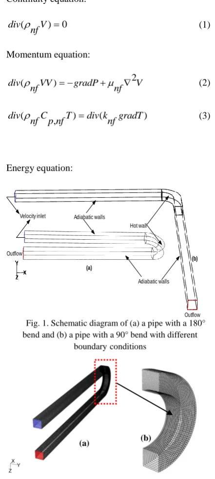
The schematic diagrams with applied boundary conditions for a 180° and 90° bend pipe are shown in Fig. 1(a) and (b), respectively. The length of the inlet and outlet portions of the return-bend pipe was 20 times the hydraulic diameter of the pipe (
0.005
Dh m) so as to ensure a fully developed laminar flow at the entrance of the bend section. Two different bend angles of 180° and 90° have been considered for the present analysis since these bend angles are commonly found in the pipe fittings of any engineering equipment. The curvature radius (
/ 2.5
Rc Dh ) was kept constant for both the bend angles. An alumina-water (Al2O3-water) nanofluid
entered the return-bend pipe at a uniform velocity of in
u
and a temperature of To300 K through the inlet. A constant wall temperature of / 1.210 Tw T was applied to the bend walls. The walls of the inlet and outletportions of the pipes were adiabatic.
For both bend angles, the heating length was kept constant in order to compare the variation in the heat transfer rate with the bend angles. The grid arrangements for the computational domain with a 180° bend is shown in Fig. 2(a), whereas Fig. 2(b) depicts the enlarged view of the grid arrangement for the bend portion of the curved pipe. It is quite evident that hexahedral cells have been deployed to mesh the computational domain in order to control the number of cells, thereby maintaining accuracy in the solution variables. Finer meshes were used near the vertical, horizontal, and curved walls of the return-bend pipe. The enlarged view of the mesh arrangement for the 180° and 90° curved bend walls subjected to a constant wall temperature are shown in Fig. 2(a) and (b).
2.2 Governing equations
The conservation equations for mass, momentum, and energy were solved for a three-dimensional computational domain as shown in Fig. 1(a) and (b). It is worth mentioning here that most nanoparticles used for practical applications are usually of sizes less than 100 nm. Thus, these finer particles may easily be fluidized in the base fluid so that the mixture is modeled as a continuous medium like that of a single-phase fluid [9, 31, 32]. In conjunction with the arguments stated above, other assumptions considered for the present study are given as follows: I. The flow in the bend pipe was considered
as steady and laminar.
II. The slip velocity between nanoparticles and base fluid is negligible, and the
thermal equilibrium persists between the continuous phase and discrete particles. III. The nanofluids were treated as
incompressible and Newtonian with constant physical properties.
IV. The thermal radiation, viscous dissipation, and compression work are negligibly small in the energy equation. Thus, these were neglected in the energy equation.
The governing equations for the conservation of mass, momentum, and energy are written in vector form [33] as follows.
Continuity equation:
( ) 0
div V
nf
(1)Momentum equation:
2
( )
div VV gradP V
nf nf
(2)
( ) ( )
,
div C T div k gradT
nf p nf nf
(3)Energy equation:
Fig. 1. Schematic diagram of (a) a pipe with a 180° bend and (b) a pipe with a 90° bend with different
boundaryconditions
Fig. 2. Grid arrangement in the computational domain with (a) a 180° bend and (b) an enlarged view of grid
arrangement for bend portion of the pipe (a)
(b)
Velocity inlet
Outflow Outflow
Hot wall Adiabatic walls
Adiabatic walls
In the above equations, V, P, and Trepresent the fluid velocity, pressure, and temperature, respectively, in the computational domain.
2.3 Boundary conditions
The Eqs. (1)–(3) were solved iteratively by applying the appropriate boundary conditions to all sides of the computational boundaries since these equations are elliptic, nonlinear, and coupled partial differential equations. In the computational domain velocity inlet boundary condition was imposed at the tube inlet through which fluid enters with the uniform axial velocity,
u
in and temperature,T
in (which is equal toT
). At the pipe outlet, the pressure outlet boundary condition would be a more realistic boundary condition since the flow and temperature fields may not be fully developed (since/ 20
x D
h ). The inlet and outlet portion of the return bends were considered as adiabatic walls. The bend walls were only applied with a uniform temperature (Tw/T 1.21). The mathematical descriptions of different boundary conditions used in the present study are given as follows.
Pipe inlet (i.e., velocity inlet):
0, ,
0 v w uuin T Tin T
, (4) Pipe outlet (i.e., pressure outlet):
n
, (5)
where
represents any physical quantity in the computational domain, andn
is the outward normal drawn to outlet of the pipe.Adiabatic walls of the pipe:
0
u v w , T T T 0
x y z
(6)
Constant temperature bend walls:
0
u v w , Tx Ty Tz Tw
(7)
2.4 Numerical solution procedure
The three-dimensional computational domain was discretized using hexahedral cells. The discretized equations for mass, momentum, and energy were integrated over the control volume to yield a set of
algebraic equations. The second-order upwind scheme was adopted for discretizing the convective and diffusion terms so as to maintain a better accuracy in the results. A staggered grid layout was employed to compute the temperature and velocity components at center of the control volume interfaces. The Semi Implicit Pressure Linked Equation
(
SIMPLE) algorithm [34] was employed for velocity coupling to solve the pressure-correction equation. The set of algebraic equations were then solved iteratively using a point implicit (Gauss-Siedel) linear equation solver in conjunction with an algebraic multi-grid solver from the ANSYS Fluent R16 program by incorporating the boundary conditions. The solutions were considered to be converged when the residuals resulting from the iterative solutions fell below 10-4 and 10-7 for the momentum and energy equations, respectively.2.5 Physical properties of the nanofluid
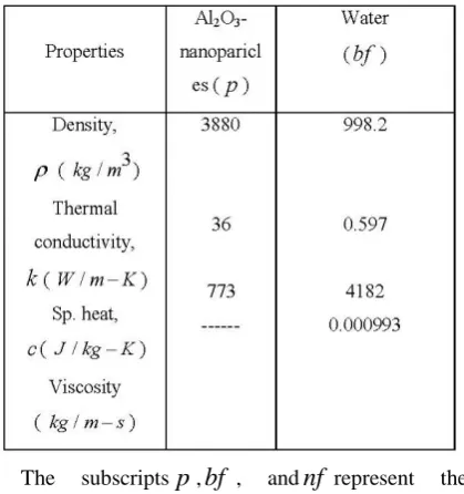
The nanoparticles were assumed to be well dispersed in the base fluid. Therefore, the thermo-physical properties of the nanofluid were evaluated from some classical well-known formulas for single-phase, constant property fluids [37]. Different thermo-physical properties of the Al2O3 nanoparticle
as well as water (i.e., the base fluid) are given in Table 1.
Table 1: Physical properties of nanoparticle and water
A. K. Barik/ JHMTR 4 (2017) 103-115 107
different equations are discussed in the following sections.
2.5.1 Density
In the present study, the temperature-independent and the volume fraction–dependent densities for Al2O3-water nanofluid were employed.
The volume fraction–dependent density for the nanofluid is calculated from Eq. (8) as suggested by different researchers [23, 25, 31]:
1
pnf bf
. (8)
The above formula commonly used for obtaining the nanofluid density was obtained from the experimental results of Pak and Cho [35].
2.5.2 Dynamic viscosity
The dynamic viscosity of the Al2O3-water
nanofluid was evaluated form the classical homogenous two-phase mixture model, neglecting the slip velocity between the phases [37] as given in Eq. (9):
2
123 7.3 1
nf r
bf
.
(9)
A least square analysis was carried out by Maiga et al. [37] to fit the experimental data of various researchers [38, 39] to obtain the above equation. The thermophoresis effect (i.e., the diffusion of particles due to temperature gradient) and the Brownian motion of particles were neglected in the above equation.
2.5.3 Specific heat
The specific heat of the mixture is obtained from Eq. (10) as has been reported by different researchers [31, 35, 36].
(1 )
c c c p
nf
bf
.
(10)
2.5.4 Thermal conductivity
The same criteria as that of the viscosity were used to determine the thermal conductivity of the nanofluid. The thermal conductivity is determined from the Eq. (11):
2
4.97
2.72
1
nfr bf
k
k
k
.
(11)
The above thermal conductivity model assumes that the nanoparticles are spherical in shape, which may not be the case in a real situation. Thus, this model under-predicts the thermal conductivity of nanofluids as has been reported in [37]. However, this model is a very simple and easy model to implement in the numerical computations. Therefore, we have used this model to evaluate the thermal conductivity of the Al2O3-water nanofluid. An
excellent analysis on the dependency of the thermal conductivity of nanofluids on temperature was given by Khanafer and Vafrai [49]. Before proceeding to the validation of the present numerical methodology, the area-weighted average Nusselt number, local Nusselt number, bulk mean temperature, and the Reynolds number based on the hydraulic diameter of the duct are given as follows.
The area-weighted average Nusselt number is given by Eq. (12):
1
NuDh Nu dA
Dh A
. (12)
The local Nusselt number is given by Eq. (13):
( )
qw Nu
Dh T T
w b
.
(13)
The area-weighted mean temperature in the computational domain is computed from the local temperature Taccording to Eq. (14):
1
T TdA
b A
.
(14)The Reynolds number based on hydraulic
diameter is given as:
Re u Dhin
Dh
.
(15)3.
Validation of numerical methodology
Attempts have been made to validate the present numerical scheme in some of the existing literature. It is worth mentioning here that there exists neither experimental nor numerical data to validate the heat transfer from a return-bend pipe with a rectangular cross section carrying an Al2O3-water nanofluid. As
-water nanofluid [26] was the only the available literature for the validation of our numerical results. Thus, the present results for axial velocity profiles were validated with the numerical results of Choi and Zhang [26] for a circular cross-section return-bend pipe. The dimensionless axial velocity profiles (
u u
/
in) were plotted (see Fig. 3[a]) against the dimensionless axial distance (AA Dh
/
), which is drawn in the mid-plane of a return-bend (180°) pipe with a rectangular cross section. The mid-plane of the 180° return-bend pipe is shown with the lineAA
in Fig. 3(b) for a better understanding of the velocity profiles. It is quite evident from Fig. 3(a) that the variation of velocity profiles along the lineAA
shows a similar trend to that of the variation reported in [26].Fig. 3(a). Variation of axial velocity along the line
AA
and (b) position of the lineAA
in the 180° bend tubeFig. 4. Variation of the Nusselt number with the number
of cells
AtRe 10
Dh , the velocity profiles for both circular as well as rectangular pipes are approximately symmetric in shape. However, the symmetric nature of the velocity profiles are distorted at a higher Reynolds number (Re 100
Dh ),
showing a higher velocity towards the outer wall of the curved pipe. At a higher Reynolds number, tangential velocity enhances the centrifugal force at the outer region of the curved pipe. As a result, the fluid flows at a higher velocity near this region. It is to be noted here that the present computed velocities are a little higher than the valuesgiven in [26]. This discrepancy can perhaps be attributed to (i) the cross section of the bend pipe and (ii) the applied thermal boundary condition. In the present study, a curved pipe with a rectangular (AR1) cross section subjected to constant wall temperature was employed; whereas in [26], a bent pipe with a circular cross section and uniform wall heat flux was used. The numerical methodology implemented in the present study was also validated with the analytical results of Muralidhar and Biswas [46] and Chakraborty [45] as shown in Fig. 4. The above literature was chosen for the validation since the flow in the above literature those studies were laminar and the cross section of the duct was square. It is evident that the present numerical methodology is capable of predicting flow behavior in square ducts quite well.
4.
Results and discussions
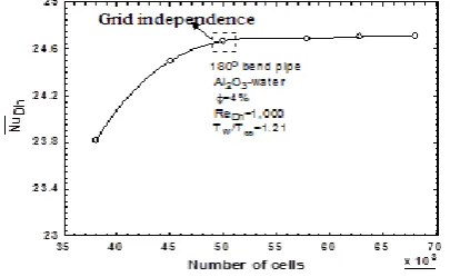
4.1 Grid sensitivity study
The grid sensitivity study carried out for the present simulation is shown in Fig. 4. A tube with a 180°bend and a unit aspect ratio (which is defined as the ratio of the vertical height b to the horizontal side
a as shown in Fig. 10[a]) carrying an Al2O3-water
nanofluid of volume fraction 4% was considered for the grid independence study. Initially, the computational domain was meshed with 38,000 cells, and then the subsequent grid refinement increased the cell size to 68,000. It was observed that the average Nusselt number was increased by 3.6% as the number of cells increased from 38,000 to 50,000; thereafter, it increased by 0.2% on increasing the number of cells to 68,000. Therefore, the computational domain with 50,000 cells was considered as an independent mesh.
0 0.1 0.2 0.3 0.4 0.5 0.6 0.7 0.8 0.9 1 0
0.5 1 1.5 2 2.5 3
AA/Dh
u
/uin
Re=10 (Present CFD)
Re= 10 (Choi & Zhang)
Al2O3-wate r nanofluid
f=4%
180o re turn be nd pipe
Square cross section
Circular cross Re=100 (Present CFD)
Re= 100 (Choi & Zhang)
section Present CFD
Choi & Zhang
A. K. Barik/ JHMTR 4 (2017) 103-115 109
4.2 Effect of Reynolds number on heat transfer rate
The variation between the Nusselt number of a pipe with a180° bend and the Reynolds number is shown in Fig. 5(a). It can be observed that the Nusselt number in the 180° bend region is subjected to a constant wall temperature increase with the Reynolds number. A higher Nusselt number is achieved when the conventional working fluid (i.e., water) is replaced by the Al2O3-water nanofluid. The
variation of dimensionless temperature along the dimensionless length (
AA Dh
/
) is depicted in Fig 5(b). It is evident from Fig. 5(b) that the nanofluid attains a lower temperature (i.e., fluid bulk temperature) as the Reynolds number is increased, and, as a result, the Nusselt number is improved. At/
0.4
AA Dh
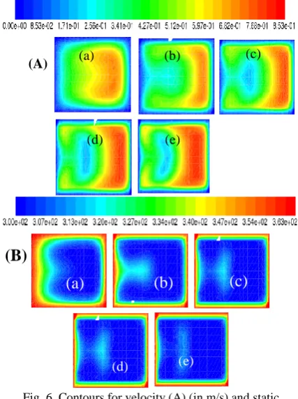
, a minimum temperature was noticed, which may be attributed to the secondary flow. The development of the secondary flow can be seen from the velocity contour plots shown in Fig. 6(A). The centrifugal force developed in the curved length of the pipe forms two counter rotating secondary vortices.Fig. 5. Variations of (a) the Nusselt number with the
Reynolds number and (b) dimensionless temperature along
/
AA Dh
Fig. 6. Contours for velocity (A) (in m/s) and static temperature (B) (in K) in an
x
y
plane at different Reynolds numbers: (a) ReDh= 100, (b) ReDh= 400, (c) Re
Dh= 800, (d) ReDh= 1,200, and (e) ReDh= 2,000
These vortices move the cold fluid from the core region to the outer wall and carry heat from the wall, and then the warm fluid near the outer wall is carried back with the secondary vortices at the inner wall and subsequently to the core of the pipe bend. As a result, the thermal boundary layer is eliminated, and the heat transfer from the wall to the bulk fluid (Al2O3-water) is enhanced. Moreover, it can be
observed from the velocity contours that the fluid velocity near the outer wall increases with the Reynolds number. This is perhaps due to the improvement in the centrifugal force, which can lead to a better mixing of hot and cold fluid due to secondary vortices [50]. The temperature contours at different Reynolds numbers are illustrated in Fig. 6(B).
4.3 Effect of volume fraction on heat transfer
The variation of the average Nusselt number with the Reynolds number in an 180° return-bend pipe at different volume fractions of the nanofluid is shown in Fig. 7. The Nusselt number was observed to increase with both the Reynolds number as well as the volume fraction. This enhancement in the heat
0 0.2 0.4 0.6 0.8 1 0
0.2 0.4 0.6 0.8 1 1.2
AA/Dh
(T
-T0
)/
(Tw -T0
)
ReDh = 100
ReDh = 800 ReDh = 1,200 ReDh = 300
ReDh = 2,000
f = 4% 180o bend Al2O3+water
AR = 1
(a)
(b)
(A) (a) (b) (c)
(d) (e)
(a)
(b)
(c)
(B)
transfer rate is attributed to the following facts: first, the thermal conductivity of the mixture increases with the particle concentration; and second, the fluid mixing is improved, leading to an increased energy transfer from the base fluid to the nanoparticles. Moreover, the Prandtl number of the nanofluid, which depends on the nanofluid viscosity and thermal diffusivity, also increases with the volume fraction. For example, the Prandtl number of the nanofluid is 7.2 at 1% volume fraction, and it increases to 12.3 at a volume fraction of 8%, registering a 70.8% hike over the former value. At
Re
Dh
2,300
, the Nusselt number improves by4.1% as the volume concentration of the nanoparticles increases from 1% to 8%. Therefore, it is always helpful to use nanofluids of a higher volume fraction for heat transfer augmentation. So, in micro- and nano-scale devices, the conventional fluid (i.e., water) may be replaced by nanofluids for better thermal management.
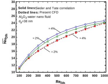
Similarly, at a particular value of volume concentration (i.e., 8%), the Nusselt number is enhanced by 120.1% as the Reynolds number increases from 100 to 2,300. The present numerical values of the Nusselt number are also compared with the Sieder and Tate correlation [41] as shown in Fig. 8. It was observed that variations in the Nusselt number with duct‟s Reynolds number shows a similar trend (i.e., increase in the Nusslet number with the volume fraction of nanofluid). However, the predicted Nusselt number is a little lower than the present computed Nusselt number. This is attributed to (i) the different boundary conditions employed and (ii) the presence a 180° return bend in the present study. In the present study, the Al2O3
nanofluid flowing through a rectangular cross-sectional duct was subjected to a constant wall temperature; whereas in the reference [42], the predicted Nusselt number was for a straight square cross-sectional duct subjected to constant wall heat flux. Thus, the present computed results are higher than the results given in reference [42]. Interestingly, it can be seen in Fig. 8 that the present computed results deviate 9.5% from the correlation given by Sieder and Tate [41], which is acceptably small deviation for engineering calculations.
4.4 Effect of duct aspect ratio (b/a) on heat transfer rate
Fig. 9(a) shows the effect of aspect ratio on the heat transfer characteristics for a 180° return-bend pipe
carrying an Al2O3-water nanofluid. The present
investigation was carried out by varying the Reynolds number as well as the aspect ratio in the range of 100ReDh 2, 300 and 1AR8, respectively. At a particular Reynolds number (
Re
Dh
2,300
), the Nusselt number is enhancedby 9.5% as the aspect ratio of the duct increases from 2 to 8. However, at a particular aspect ratio (
8
AR
) the Nusselt number increases by 139.5% when the Reynolds number increases from 100 to 2,300. The improved heat transfer rate for a high– aspect ratio duct is attributed to the increased heat transfer surface. AtRe 100
Dh , the non-dimensional velocity profiles at different duct aspect ratios along the line
AA
/a are shown in Fig. 9(b). The orientation of the lineAA
, a, and b are shown in the Fig. 9(a). The abscissa of Fig. 9(b) have non-dimensionalized with a instead of the hydraulic diameter. This was chosen because the hydraulic diameter of the duct changes as the aspect ratio (b/a) increases. However, the length of the side represented as „a’ is kept fixed although the aspect ratio increases. It can be seen in Fig. 9(b) that the maximum axial velocity shifts to the inner wall with the aspect ratio, which resembles a fully developed pipe flow. This shifting of the maximum axial velocity carries more heat from the inner wall of the pipe.Fig. 7. Variation of the Nusselt number with the Reynolds number as a function of nanofluid volume concentration
Fig. 8. Comparison of the variation of the Nusselt number with the duct‟s Reynolds number
100 200 300 400 500 600 700 800 900 1000 10
12 14 16 18 20 22 24 26 28 30
ReDh
N
uD
h
Sieder and Tate correlation
Al2O3-water nano fluid
dp=38 nm
f = 2%
f = 4% f = 2%
f = 4% Solid line s:
A. K. Barik/ JHMTR 4 (2017) 103-115 111
Fig. 9. Variation of the Nusselt number with the Reynolds number as a function of the duct aspect ratio (b/a)
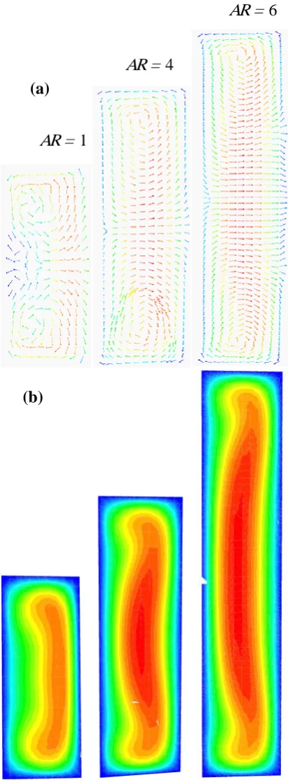
Moreover, Chandratilleke and Nursubyakto‟s [40] numerical study of a curved rectangular duct reported that the heat transfer for a curved duct increases with the aspect ratio because of the existence of vigorous secondary flow. In the present work, a similar observation can be noticed from the velocity vector plots as shown in Fig. 10(a). In a high–aspect ratio duct, perhaps the buoyancy force dominates the centrifugal force, which causes the secondary vortices to move from the outer wall to the inner wall of the duct as has been depicted in the velocity counters plots (i.e., Fig. 10[b]). At a particular aspect ratio, the Nusselt number also increases with the duct‟s Reynolds number because of the strong centrifugal force, which leads to the secondary vortices.
Fig. 10. (a) Velocity vectors and (b) velocity contours at
Re 100
Dh and
4%500 1000 1500 2000
12 16 20 24 28
ReDh
N
uD
h
f=4% Al2O3 Nano fluid
AR=1 AR=4
AR=8AR=6
180 retun bend AR
b
a AR = b/a
0 0.2 0.4 0.6 0.8 1
0 0.4 0.8 1.2 1.6
AA/a
u
/uin
AR = 2 AR = 4 AR = 6 AR = 8
f = 4% ReDh = 100
180o bend
(a)
(b)
AR = 1
AR = 4
(a)
(b)
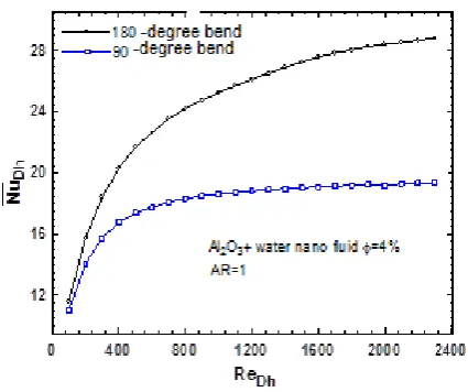
Fig. 11. Variation of the Nusselt number with Reynolds number at different bend angles
Fig. 12. Variation of Nusselt number with duct‟s Reynolds number as a function of nanoparticle diameter
4.5 Effect of bend angle on heat transfer rate
Fig. 11 shows the effect of bend angle on the heat transfer rate. The present comparison was made by maintaining a constant aspect ratio (i.e.,
AR
1
) as well as a constant nanofluid volume fraction. The length of the heating region was kept constant so that a clear comparison could be established in terms of the heat transfer capability of the two different types of bends. A constant wall temperature was applied on the bend walls. It is worth mentioning here that the radii of the curvature for both the cases were kept constant.Therefore, the curved length in a 90° bend was reduced. However, the length of the pipe subjected to a constant wall temperature remained the same as that of a pipe with a 180° bend. Thus, in the case of a 90° bend, some portion of pipe wall was made straight although the heating lengths for both the
bends remained the same. Since the length of the curved portion of the pipe was reduced, the appearance of secondary vortices may not be so rigorous as compared to a 180° bend. The augmentation of the heat transfer in a curved pipe is because of the secondary vortices that drive the fluid from the inner to the outer wall, imparting a strong mixing force between the cold and hot fluids. The reduced strength of these secondary vortices in a pipe with a 90° bend may not able to create a strong mixing force, so the heat transfer enhancement in a 90° bend is less than in a 180° bend as shown in Fig. 11. For a pipe with a 90°bend, the Nusselt number curve becomes flat afterRe 1, 200
Dh . However, the Nusselt number continuously increases with the Reynolds number for a pipe with a 180° bend. For example, at Reynolds numbers of 500 and 2,300, the Nusselt numbers for a 180° bend increased by 24.1% and 48.5%, respectively, as compared to a 90° bend.
4.6 Effect of nanoparticles size on heat transfer
enhancement
The effect of the size of nanoparticles on heat transfer enhancement is depicted in Fig. 12. The physical properties of 38-nm diameter nanoparticles are shown in Table 1. In the present study, the physical properties of two other diameters of Al2O3
nanoparticles were taken from reference [43]. In order to compare the heat transfer rate, the volume fraction and the duct‟s geometrical aspect ratio were fixed at 4% and 1, respectively. At a particular Reynolds number as well as volume fraction, the heat transfer enhancement is greater with smaller nanoparticles than larger ones. A uniform distribution of heat in the base fluid was achieved with smaller nanoparticles as compared to larger nanoparticles. Similar observations were reported by Namburu et al. [44] in their numerical study. They reported that smaller particles can improve the fluid viscosity on the basis of a higher contact area with the base fluid. As a result, the Prandtl number of the fluid increases, which yields a higher Nusselt number. Moreover, the higher Nusselt number with a smaller particle size was also reported in reference [15]. A stronger Brownian motion by the smaller particles further improves the heat transfer rate. The above effects enhance heat transfer when smaller nanoparticles are used.
400 800 1200 1600 2000
10 14 18 22 26 30
ReDh
N
uD
h Al2O3f=4%
AR=1
180o bend
dnp=25 nm
dnp=38 nm
A. K. Barik/ JHMTR 4 (2017) 103-115 113
5.
Conclusion
In the present study, the laminar forced convective heat transfer of an Al2O3-water nanofluid
flowing through a curved rectangular pipe was studied numerically in a three-dimensional computational domain using the finite volume method. The effects of different pertinent parameters, such as the duct‟s Reynolds number, the volume fraction of nanoparticle, the diameter of the nanoparticles, the aspect ratio of the duct, and the duct bend angle on the heat transfer rate were investigated, and the following conclusions are drawn from the study:
(i)The results revealed that the heat transfer rate is augmented significantly when the base fluid (i.e., water) is replaced by an Al2O3-water nanofluid. At
a particular Reynolds number ( Re 2, 300
Dh )
and aspect ratio (AR1) of the duct, the Nusselt number is increased by 4%. However, the heat transfer rate is increased by 139.5% as the Reynolds number is increased from 100 to 2,300 at the volume fraction of 8%. The computed heat transfer rate (i.e., the Nusselt number) was also validated with the modified Sieder and Tate [41] correlation.
(ii)It was observed that the Nusselt number for a pipe with a 180° bend increases with the duct aspect ratio. The hydrodynamic characteristics of the flow change with the aspect ratio, which shows a shift of the maximum velocity from the outer wall to the inner wall. The appearance of secondary vortices due to centrifugal force further increases the heat transfer rate by imparting a better mixing between the cold and hot streams of fluid.
(iii)A higher heat transfer rate was achieved in a pipe with a 180° bend as compared to a pipe with 90° bend. For a 90° bend, the Nusselt number increased insignificantly at higher Reynolds numbers (i.e.,
Re
Dh
1, 200
). The lower Nusseltnumbers for a 90° bend at a particular value of Reynolds number as well as volume fraction is attributed to the reduced curve length of the pipe, which in turn creates weaker secondary vortices to impart the mixing of fluids.
(iv)The nanofluid with the smaller particles was found to be a better heat transfer enhancer than the nanofluid with bigger particles. A careful experimental study needs to be carried out to further investigate the heat transfer enhancement mechanisms that consider the effects of the particle
diffusion mechanism as well as the inter-particle collisions.
Nomenclature
Nu Dh Area-weighted average Nusselt number
AR Aspect ratio (
b a
/
) Tb Bulk mean temperature (K) Re
Dh The duct‟s Reynolds number based on the hydraulic diameter of the duct
qw Heat flux of an isothermal surface (W m-2)
Dh
Hydraulic diameter of the duct (m)0 T
Inlet temperature (K) u
in Inlet velocity (m sec
-1)
P Pressure (N m-2)
RcRadius of curvature (m) C p Specific heat, (J kg-1 K-1)
k
Thermal conductivity (W m-1 K-1), ,
u v w
Velocity in x, y, and z directions (m sec-1)Tw Wall temperature (K)
Density (kg m-3)
Kinematic viscosity (N sec m-2)
Volume fractionbf
Base fluidin
Inletnf
Nanofluidw
WallReferences
[1]. A. Bejan, S. Lorente, “Thermodynamic optimization of flow geometry in mechanical and civil engineering”, Journal of Non-Equilibrium Thermodynamics, 26, 305-354, (2001).
[3]. H. Najafi, B. Najafi, “Multi-objective optimization of a plate and frame heat exchanger via genetic algorithm”, Heat Mass Transfer, 46, 639-647, (2000).
[4]. K.V. Liu, S.U.S. Choi, K.E. Kasza, “Measurement of pressure drop and heat transfer in turbulent pipe flows of particulate slurries”, Argonne National Laboratory Report, ANL-88-15, (1998).
[5]. C.W. Sohn, M.M. Chen, “Microconvective thermal conductivity in dispersed two-phase mixture as observed in low velocity Couette flow experiment‟‟, ASME Journal of Heat Transfer, 103, 47-51, (1981).
[6]. M.C. Roco, C.A. Shook, “Modelling of slurry flow: the effect of particle size‟‟, The Canadian Journal of Chemical Engineering, 61, 494-503, (1983).
[7]. A.S. Ahuja, “Augmentation of heat transfer in laminar flow of polystyrene suspension”, Journal of Applied Physics, 46, 3408-3425, (1975).
[8]. S.U.S. Choi, Z.G. Zhang, W. Yu, F.E. Lookwood, E.A. Grulke, “Anomalously thermal conductivity enhancement in nanotube suspension”, Applied Physics Letters, 79, 2252-2254, (2001).
[9]. Y. Xuan, Q. Li, „„Heat transfer enhancement with nanofluids”, International Journal of Heat and Fluid Flow, 21, 58-64, (2000).
[10]. X. Wang, A.S. Mujumdar, “Heat transfer characteristics of nanofluids: a review”, International Journal of Thermal Sciences, 46, 1-19, (2007).
[11].S. Kakaç, A. Pramuanjaroenkij, „„Review of convective heat transfer enhancement with nanofluids”, International Journal of Heat and Mass Transfer, 52, 3187-3196, (2009).
[12]. S.Z. Heris, M.N. Esfahany, S.G. Etemad, „„Experimental investigation of convective heat transfer of Al2O3/water nanofluid in circular tube”, International Journal of Heat and Mass Transfer, 28, 203-210, (2007).
[13]. S.Z. Heris, S. G. Etemad, S. G., M.N. Esfahany, „„Experimental investigation of oxide nanofluids laminar flow convective heat transfer‟‟, International Communication of Heat and Mass Transfer, 33, 529-535, (2006).
[14]. K.B. Anoop, T. Sunderrajan, S.K. Das, “Effect of particle size on convective heat transfer in nanofluids in developing region”, International Journal of Heat and Mass Transfer, 52, 2189-2195, (2009).
[15]. C.T. Nguyen, G. Roy, C. Gauthier, N. Galanis, “Heat transfer enhancement using Al2O3-water nanofluid for an electronic liquid cooling system”, Applied Thermal Engineering, 27, 1501-1506, (2007).
[16]. S.K. Das, N. Putra, P. Thiesen, W. Roetzel, „„Temperature dependence of thermal conductivity enhancement for nanofluids”, ASME Journal of Heat Transfer, 125, 567-574, (2003).
[17]. J.C. Maxwell, „„A Treatise on Electricity and Magnetism.‟‟ vol. 1, Second ed., Clarendon Press, Oxford, UK, (1881).
[18]. R.L. Hamilton, O.K. Crosser, “Thermal conductivity of heterogeneous two component systems”, Industrial Engineering Chemistry Fundamentals, 1, 187-191, (1962).
[19]. K.Y. Leong, R.T. Saidur, M.I. Mahlia, Y.H. Yau, “Entropy generation analysis of nanofluid flow in a circular tube subjected to constant wall temperature”, International Communications in Heat and Mass Transfer, 39, 1169-1175, (2012).
[20]. A. Tabrizi, H.R. Seyf, “Analysis of entropy generation and convective heat transfer of Al2O3 nanofluid flow in a tangential micro heat sink”, International Journal of Heat and Mass Transfer, 55, 4366-4375, (2012).
[21]. H.R. Seyf, M. Feizbakhshi, “Computation analysis of nanofluid effects on convective heat transfer enhancement of micro-pin-fin heat sinks”, International Journal of Thermal Sciences, 58, 168-179, (2012).
[22]. M. Nazififard, M. Nematollahi, K. Jafarpur, K.Y. Suh, “Numerical simulation of water-based Alumina nanofluid in sub-channel geometry‟‟, Science and
Technology of Nuclear Installations,
doi:10.1155/2012/928406, (2012).
[23]. V. Bianco, F. Chiacchio, O. Manca, S. Nardini, “Numerical investigation of nanofluids forced convection in circular tubes”, Applied Thermal Engineering, 29, 3632-3642, (2009).
[24]. R. Vajjha, D.K. Das, P.K. Namburu, “Numerical study of fluid dynamic and heat transfer performance of Al2O3 and CuO nanofluids in the flat tubes of a radiator”, International Journal of Heat and Fluid Flow, 31, 613-621, (2013).
[25]. A. Akbarinia, A. Behzadmehr, “Numerical study of laminar mixed convection of nanofluid in horizontal curved tubes”, Applied Thermal Engineering, 27, 1327-1337 (2007).
[26]. J. Choi, Y. Zhang, “Numerical simulation of laminar forced convection heat transfer of Al2O3-water nanofluid in a pipe with return bend”, International Journal of Thermal Sciences, 55, 90-102, (2009).
[27]. A.A. Minea, “Numerical simulation of nanoparticle concentration effect on forced convection in a tube with nanofluids”, Heat Transfer Engineering, 36, 1144-1153, (2015).
[28]. L. Zhang, M. Bai, D. Guo, “Effect of vibration on forced convection heat transfer for SiO2-water nanofluids” Heat transfer Engineering, 36, 452-461, (2015).
[29]. S.K. Das, S.U.S Choi, H.E. Patel, “Heat Transfer in Nanofluids- A Review”, Heat Transfer Engineering, 27, 3-19, (2006).
[30]. S.Z. Haris, Z. Edalati, S.H. Noie, O. Mahian, “Experimental investigation of Al2O3/water nanofluid through equilateral triangular duct with constant wall heat flux in laminar flow”, Heat Transfer Engineering, 35, 1173-1182, (2014).
A. K. Barik/ JHMTR 4 (2017) 103-115 115
[32]. M. Mahmoodi, “Numerical simulation of free convection of a nanofluid in L-shaped cavities”, International Journal of Thermal Sciences, 50, 1731-1740, (2011).
[33].Z.U.A. Waris, „„Fluid Dynamics Theoretical and Computational Approaches‟‟, Second ed. CRC Press, Boca Raton, Florida, USA, (1999).
[34]. S.V. Patankar, “Numerical Heat Transfer and Fluid Flow”, Hemisphere Publishing Corporation, New York, (1980).
[35]. B.C. Pak, Y.I. Cho, “Hydrodynamic and heat transfer study of dispersed fluids with submicron metallic oxide particles”, Experimental Heat Transfer, 11, 151-170, (1998).
[36]. S.J. Palm, G. Roy, C.T. Nguyen, „„Heat transfer enhancement with use of nanofluids in radial flow cooling systems considering temperature dependent properties”, Applied Thermal Engineering, 26, 2209-2218, (2006).
[37]. S.E.B. Maiga, C.T. Nguyen, N. Galanis, G. Roy, “Heat transfer behaviours of nanofluids in a uniformly heatedtube,” Superlattices Microstructures, vol. 35, (2004) pp. 543–557.
[38]. X. Wang, X. Xu, S.U.S., Choi, “Thermal conductivity of nanoparticle–fluid mixture”, Journal of Thermophysics and Heat Transfer, 13, 474–480, (1999).
[39]. S. Lee, S.U.S. Choi, S. Li, J.A. Eastman, “Measuring thermal conductivity of fluids containing oxide nanoparticles”, Journal of Heat Transfer, 121, 280–289, (1999).
[40]. T.T. Chandratilleke, Nursubyakto, “Numerical prediction of secondary flow and convective heat transfer in externally heated curved rectangular ducts”, International Journal of Thermal Sciences, 42, 187–198, (2003).
[41]. E. N. Sieder, G. E. Tate, “Heat Transfer and pressure drop of liquid in tubes”, Ind. Eng. Chem., 28, 1429-1435, (1936).
[42]. S.Z. Heris, T.H. Nassan, S.H. Noie, H. Sardarabadi, M. Sardarabadi, “Laminar convective heat transfer of Al2O3/water nanofluid through square cross-sectional duct”, International Journal of Heat and Fluid Flow, 44, 375-382, (2013).
[43]. B. Farajollaha, S.G. Etemad, M. Hojjat, “Heat transfer of nanofluids in a shell and tube heat exchanger”, International Journal of Heat and Mass Transfer, 53, 12-17, (2010).
[44].P.K. Namburu, D.K. Das, K.M. Tanguturi, R.S. Vijjha, “Numerical study of fluid flow and heat transfer characteristics of nanofluids considering variable properties”, International Journal of Thermal Sciences, 48, 293-302, (2009).
[45]. G. Chakraborty, “A note on methods for analysis of flow through microchannels”, International Journal of Heat and Mass Transfer, 51, 4583-4588, (2008).
[46]. K. Muralidhar G. Biswas, „„Advanced engineering fluid mechanics‟‟, Norosa Publishing House, New Delhi, (2005).
[47]. N.T.R. Kumar, P. Bharamara, M.M. Addis, L. S. Sundar, M.K. Singh, A.C.M. Sousa, “Heat transfer, friction factor and effectiveness analysis of Fe3O4/water nanofluid flow in a double pipe heat exchanger with return bend”, International Communications in Heat and Mass Transfer, 81, 155-163, (2017).
[48]. L. Colla, L. Fedele, M.H. Buschmann, “Laminar mixed convection of TiO2-water nanofluid in a horizontal uniformly heated pipe flow”, International Journal of Thermal Sciences, 97, 26-40, (2015).
[49]. K. Khanafer, K. Vafai, “A critical synthesis of thermophysical characteristics of nanofluids”, International Journal of Heat and Mass Transfer, 54, 4410-4428, (2011).