Author name / JHMTR 00 (2013) 000–000 21
Corresponding author: Mohammad Hossein Tavakoli, Physics Department, Bu-Ali Sina University, P.O.Box: 65174, Hamedan, Iran. Tel: +98 81 38271541, Fax: +98 81 38280440
Email: [email protected] & [email protected]
1.Introduction
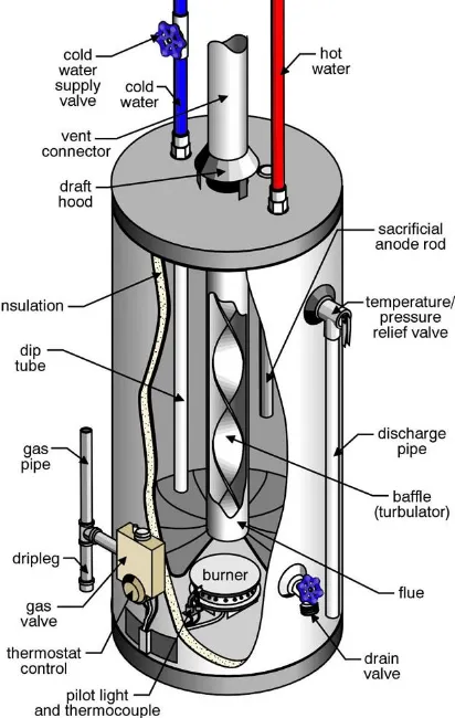
Among the energy components, heating systems that use mainly fossil fuels are particularly important. Rising demands for gas on one hand, and limited gas reserves on the other hand, are sensible more than before. Consequently, the efficiency of gas consumption in all consumers is a crucial factor [1]. One of these systems is the gas-fired tank water heater that produces domestic hot water at home. Storage water heaters are by far the most common type used in many countries. These systems heat and store water in a tank so that hot water is available at any time. As hot water is drawn from the top of the tank, cold water enters from the bottom of the tank and then is heated [2]. The heating source can be electricity, gas or oil. As Figure 1 shows, a gas tank water heater consists of different parts. These parts include a burner at the
bottom of the tank,which heats the water, an inner steel tank that holds the water being heated, fire tube (or chimney) thatis in the middle of system, baffle plates usually made of metal and inside the fire tube, thermal insulation that surrounds the tank to decrease the amount of heat lost to the surrounding, dip tube to allow cold water to enter the tank, pipe to allow hot water to leave the tank, thermostat that reads and controls the temperature of the water inside the tank, and a vent hood that lies at the exit of the combustion products. Air enters the combustion chamber, combines with the gas fuel, the mixture is ignited, and then the resulting combustion heat is transferred to the water through metal surfaces of the storage tank. The vent pipe is an exhaust pipe that carries the by-products of combustion to the outside and serves as a heat exchanger. This pipe is typically surrounded by the water tank and often contains baffles to slow the escape of these gases through the vent, thus
Numerical study of fluid flow and heat transfer in a gas-tank
water heater
Mohammad Hossein Tavakoli
*and Khatereh Moharramkhani
Physics Department, Bu-Ali Sina University, Hamedan, Iran Journal of Heat and Mass Transfer Research 2 (2015) 21-29
Journal of Heat and Mass Transfer Research
Journal homepage: http://jhmtr.journals.semnan.ac.ir
A B S T R A C T
Influence of a vent hood at the exit of exhaust flue gas and flue baffles in the fire tube on the temperature and flow fields of a gas tank water heater, as well as the structure and amount of heat transferred to the water tank has been studied numerically using two-dimensional steady state finite element simulation. Observations show that without a vent hood, there is a downward gas flow in the flue and a strong vortex in the lower burner chamber. Using a vent hood prevents the gas back flow into the flue, and placing the flue baffles increases the heat delivered to the water
© 2015 Published by Semnan University Press. All rights reserved. PAPER INFO
History:
Received 02 April 2014 Received in revised form 06 June 2014
Accepted 27 July 2014
Keywords:
Fluid flow Heat transfer Tank water heater Computer simulation
22 M.H. Tavakoli / JHMTR 2 (2015) 21-29
allowing more time for heat to be transferred to the water around the pipe. Thermostatic controls regulating the temperature of the water areusually located near the mid-section of heaters.
The proper mixture of additional air with combustion or exhaust gasses is important in fuel-fired water heaters to assist the combustion products moving upwardwithin the vent pipe to the outdoors [3-5]. If their escape is
impeded or blocked, serious problems can develop. To assure this proper mixture, gas-fired water heaters are equipped with a 'cone-shaped' draft hood on the vent pipe, as it emerges from the tank.
Some gasor oil-fired water heaters may also be equipped with vent dampers on the vent pipe. This energy-saving device automatically 'closes' the vent pipe to prevent the escape of heat to the flue when the main burner is not being fired. This, in turn, slows down the rate at which the water in the tank cools down.
The tank water heaters have been a research topic for many years, and so many mathematical
Fig. 1. A schematic view of the gas
water-storage heater and its components [16].
models, experiments and simulation programs have been reported for these systems [6-15].
In this paper, influence of the flue baffles placed in the fire tube and a vent hood at the exit of the combustion products on the temperature field, fluid flow and heat transfer structure of a gas tank water heater is studied numerically using two-dimensional steady state finite element method. To do so, first a mathematical model containing assumptions, governing equations and boundary conditions is described, and then the obtained numerical results are presented and explained comprehensively.
2.CFD analysis of thetankwaterheater
2.1 Assumptions and governing equations
The computational model of the considered gas tank water heating system is a three-phase (water, gas and solid) model. The simplifications and assumptions for the model are: (1) The system runs at a steady state and is axially symmetric. Therefore, all temperature and flow fields discussed in this article are limited to two dimensions. (2) Both water and gas flows are incompressible and Newtonian. (3) Specific heat of water and gas is constant. (4) Flows are layered, smooth and stable. (5) The mass flow rate at the inlet and outlet is zero. Due to a density change for heating process, the Boussinesq approximation is used in the equations of momentum conservation. The momentum and energy equations are linked and must be solved simultaneously [17,18]. For a complete solution of the equations, the continuity equation should be considered. Thus, the basic equations in direction of r and z are:
2
2 2
1
( ) [ ( )
]
r r r
r z
r r
v v p v
v v r
r z r r r r
v v z r (1) 2 2 0 1 ( ) [ ( ) ] ( )
z z z z
r z
v v p v v
v v r
r z z r r r z
g T T
(2) 1
( ) z 0
r
v rv
r r z
23 M.H. Tavakoli / JHMTR 2 (2015) 21-29
2
2
1
[ ( ) ] r z
T T T T
r v v
r r r z r z
(4)
whereV( , )v vr z is the fluid velocity vector, Tis the temperature,ρis the density,βis the thermal expansion coefficient,is viscosity coefficient of
fluid and is called the diffusivity coefficient. In order to convert two Navier-Stocks and continuity equations to one equation, we need the stream function: 1 z v r r and 1 r v r z (5)
where ψ is the stream function. In parts that circulating flow is considered, the following equation of vorticity (ω) is applied [19]:
2 2
2 2
1 1
( )
r r r r z
(6)
2.2 Boundary conditions
At the rigid surfaces, no-slip condition is used. In addition, the inlet air temperature in the combustion chamber is assumed 27oC. At the outer
surfaces of water heater, heat dissipation via radiation and convection are considered:
4 4
ˆ a a
T
k h T T T T
n
(7)
where k is the thermal conductivity, his the convection (Newtonian) heat transfer coefficient,
ˆ
nis the unit normal vector, σ is the
Stefan-Boltzmann constant, εis the emissivity and Tais the ambient temperature of the system.
2.3 Computational domain
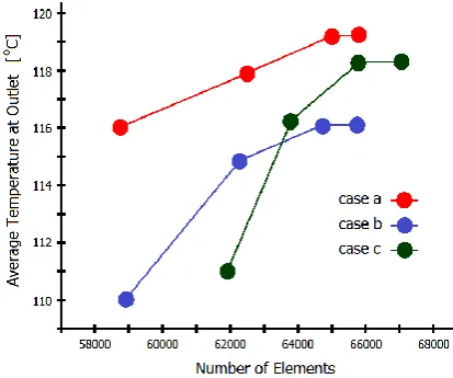
We consider three cases of a gas tank water heating system for our computation, shown in Figure 2. They are:
case a - without vent hood and flue baffles, case b - with vent hood and without flue baffles, and
case c – with vent hood, flue baffles and damper.
In case c, in order to enhance the heat exchange between the exhaust flue gas and the water within the tank, baffles are secured in the exhaust flue. A
Fig. 2. Sketch of three gas tank water heating systems considered in our computations, (a) without vent hood and flue baffles, (b) with vent
hood and without flue baffles, and (c) with both vent hood and flue baffles.
chain of discs is suspended within the flue to retard the rising gases, so that the sidewall of the flue absorbs heat and exchanges it with the liquid disposed thereabout.
2.4 Grid generation and numerical solution
24 M.H. Tavakoli / JHMTR 2 (2015) 21-29
of water heater has different resolutions at different locations.Therefore, for a better performance of the software, an optimal mesh structure with a fine grid in regions with high field gradients such as flue baffles, vent hood, walls and burner has been selected, which could optimize the required memory and computation time with sufficient accuracy. It is also suggested that prior to using an analysis technique on a new configuration, the technique should be validated. The validation process has been done in two ways, (a) Using some known (respected) test cases [FlexPDE-Help], and (b) Influence of changes in boundary conditions on the obtained solutions.
3.Results and Discussion
In Figure 4, the temperature distribution of system is shown for three considered cases. Heat transfer takes place through the system via three mechanisms of conduction, convection and radiation. A part of the energy of combustionproducts raises the temperature of the fire tube and tank walls, and thus the energy is transferred to the water within the tank via conduction. In all cases, cold air inserts into the combustion chamber via intake window (open hole to the atmosphere) positioned at the lowest chamber, and makes this area to be the coldest part of the system. Whenthere is a vent hood (case b), release of the combustion products to the outside of the system is increasing, so less heat is transferred to the tank wall compared to case a. This causes increasing temperature difference between the fire tube and the tank water, which is shown by decreasing the temperature of the water tank in
Fig. 3. Grid independency study for the average temperature at outlet.
Figure 4(b). In case c, placing the flue baffles in the fire tube delays heat transferring to the outlet. Therefore, the heat is diverted to the water tank more effectively than other two cases, which is displaced clearly by increasing the temperature of the water tank in Figure 4(c). It can be seenthat the minimum temperature of water is located at the lower left corner of the tank and the maximum at the upper corner of fire tube, which is about the boiling point of water.
25 M.H. Tavakoli / JHMTR 2 (2015) 21-29
Fig.4. Temperature distribution of the system in three considered cases (a) without vent hood and flue baffles, (b) with vent hood and without flue baffles, and (c) with both vent hood and flue baffles.
26 M.H. Tavakoli / JHMTR 2 (2015) 21-29
These gasses are harmful to breathe and need to be vented outside of the house. So, case a is not a safety configuration and is not recommended [3,4,21].In case b, placing a vent hood at the exhaust flue causes an increase in releasing the combustion products from the fire tube, and prevents the downward flow of these products into the flue too, Figure 6(b). In other words, it completely transfers all products of combustion and vents gasses to the outside without considering
the vent or spillage at the draft hood. In addition, the related problem of air needed for combustion is solved. For this reason, the formed gas vortex in the lowest chamber is quite small and weak, so the inlet air from the intake window is markedly strong which improves the combustion efficiencies of the tank water heater, Figure 6(c). Because of high outlet flow via the vent hood in this case, the transferred heat to the water is reduced to 540 W Fig.6. Distribution of velocity vectors of water and gas in case b- with vent hood and without flue baffles (a) water
27 M.H. Tavakoli / JHMTR 2 (2015) 21-29
(Nusselt Number Nucase b8.9 ) from 910 W in case a (Nucase a12.6). For this reason, the required time to reach the final water temperature is increased compared to case a [21], which
illuminatesthe low efficiency of this system. It is important to note thatbecause of the zigzag flow pattern caused by the vent hood, there is a dead space just above it and close to the centerline, where gas recirculates with low velocity resulting Fig.7. Distribution of velocity vectors for water and gas in case c- with vent hood and flue baffles (a) water
28 M.H. Tavakoli / JHMTR 2 (2015) 21-29
in a reduction in the amount of combustion products exiting.
In case c, three flue baffles, and a damper are located in the fire tube in order to increase the
delivered heat to the water tank. Baffles and
damper help to direct flue gases in radial direction
[7,15,22,23].Gas particles within the fire tube are
diverted to the tank wall with collisions to the flue
baffles, so their energy can be transferred to water
simply and then move out with less energy in the
fire tube, Figure 7(b). For this reason, these
particles spend more time in the chimney,and also a low difference of particles’ velocity as well as a
thin velocity boundary layer thickness is formed in
that space. Therefore, energy is transferred rapidly
to the adjacent layers. In this case, the maximum
amount of heat can betransferredfrom the hot
medium, i.e. flue gases into the water part, i.e. cold
medium (1020worNucase c13.8), Table 1. This is visible in Figure 4(c), which represents the highest
temperature of water tank compared to other cases.
In addition, the rate of cold air intakein the
combustion chamber is quite high and strong,
Figure 7(c), which can provide enough air needed
for a complete combustion.
4.Conclusions
In this paper, two-dimensional steady state numerical simulations for three cases of agas storage water heater are performed to reveal the effects of vent hood, damper and baffles on the flow filed and heat transfer. From the above calculations, we can conclude that:
In case a, there is a downward gas flow in the flue and a strong vortex in the lower
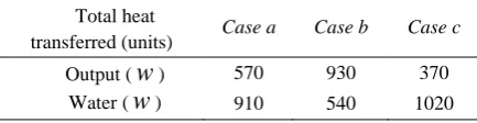
Table 1. Detailed information about the total heat transferred to the water and outside for the three
considered cases.
Total heat
transferred (units) Case a Case b Case c
Output (
w
) 570 930 370Water (
w
) 910 540 1020burner chamber. The formed gas eddy in the lower combustion chamber prevents arrival of the necessary air fora complete combustion.
A draft hood positioned at the top of the flue (case b) prevents the backflow of air into the flue,but the delivered heat to the water is not efficient.
The introduction of the flue baffles and damper (case c) results in an increase in the residence time of hot gases in the flow duct. Consequently, it reduces the temperature of flue gases, and leads to a higher heat transfer rate to the water and therefore makes the water heater more efficient.
It should be mentioned that a proper baffle design (location and inclination angle)would provide an optimal performance of water heater. The detailed knowledge of the heat transfer and flow distribution provided in this investigation may serve as a basis for further optimization of gas storage water heaters.
References
[1]. M. Krarti, Energy Auditing of Building Systems – An Engineering Approach, CRC Press, (2000).
[2]. http://oee.nrcan.gc.ca/equipment/heating/806?attr=4
[3]. K.F. Michaelsen, K. Taudorf, Danger of Gas Water Heaters, the Lancet, 322,229-230, (1983).
[4]. W.R. Chang, C.L. Cheng, Carbon monoxide transport in an enclosed room with sources from a water heater in the adjacent balcony, Building and Environment, 43,861-870, (2008).
[5]. O. Aydin, Y.E. Boke, An experimental study on carbon monoxide emission reduction at a fire tube water heater, Applied Thermal Engineering, 30, 2658-2662, (2010).
[6]. G. Gutierrez, F. Hincapie, J.A. Duffie, W.A. Beckman, Simulation of forced circulation water heaters; effects of auxiliary energy supply, load type and storage capacity, Solar Energy, 15,287-298, (1974).
[7]. G.N. Tiwari, N.K. Dhiman, Effect of the baffle plate on transient performance of built-in-storage water
heater, Energy Conversion and
Management,23,151-155, (1983).
[8]. T.W. Abou-Arab, M.O. Othman, Y.H. Najjar, N.T. Ahmad, Combustion and heat transfer characteristics for a dual-fuel cylindrical water heater model,Fuel,69,485-489, (1990).
[9]. A.K. Kar, K.M. Al-Dossary, Thermal performances of water heaters in series, Applied Energy,52,47-53, (1995).
29 M.H. Tavakoli / JHMTR 2 (2015) 21-29
[11].M. Kim, M.S. Kim, J.D. Chung, Transient thermal behavior of a water heater system driven by a heat pump, International Journal of Refrigeration,27,415-421, (2004).
[12].A.A. Hegazy Effect of inlet design on the performance of storage-type domestic electrical water heaters, Applied Energy, 84, 1338-1355, (2007).
[13].D.S. Sowmy, R.T.A. Prado Assessment of energy efficiency in electric storage water heaters, Energy and Buildings, 40, 2128-2132, (2008).
[14].S. Tajwar, A.R. Saleemi, N. Ramzan, S. Naveed Improving thermal and combustion efficiency of gas
water heater, Applied Thermal
Engineering,31,1305-1312, (2011).
[15].M. MoeiniSedeh, J.M. Khodadadi Energy efficiency improvement and fuel savings in water heaters using baffles, Applied Energy, 102,520-533, (2013).
[16].http://www.atlantarealestateinspection.com/
[17].F.P. Incropera, D.P. De Witt Introduction to Heat Transfer, John Wiley and Sons,(1996).
[18].I.H. Shames, Mechanics of Fluids, Mc-Graw-Hill, New York, (1982).
[19].J.P. Holman, Heat Transfer, Mc-Graw-Hill, New York, (1990).
[20].http://www.Pdesolutions.com
[21].K. Moharramkhani, M.Sc. Thesis, Bu-Ali Sina University, (2010).
[22].Technical Manual, T.M. 5-650Central Boiler Plants, Publications of the Headquarters, United States Army Corps of Engineers, (1989).
III
9314
،
لوا
هرامش
-
مرج و ترارح لاقتنا
رد شهوژپ
ی
للملا
ن
ی
ب هلجم
رادنزخم نکمرگبآ کی رد ترارح لاقتنا و هراش نایرج یددع یسررب
یزاگ
م
یلکوت نیسح دمح
*
،
یناخمرحم هرطاخ
،کیزیف هورگ هدکشناد
هیاپ مولع ، هاگشناد انیس یلعوب ، نادمه
هلاقم تاعلاطا
هدیکچ
هتتتلاقم قتتتفایرد 93
دادرتتتخ
9313 هلاقم شریذپ 5
دادرم 9313 ارتتحا هتقنعم رد ظناتم تاعنتم و هروتنت هتلول یتجورخ رد ریدتیت کتههلا کتی ریثات
و اتمد یاه نادیم یور هراتش ناتیرج
، هدتش رتقتنم یاتمرگ رادتقم و راتخاتس نیتنچمه و
بآ نزخم هب ی اتگ رادتنزخم نکمرتگبآ کی رد
ی اتس هیاتش ا هدانتتسا اتب یددتع روتطب
هدتتمآ قتتسدب یاتتتن هقتتسا هدتتش یتتسررب یهاتتنتم رتتمانع شور اتتیاپ قتتلاح یدتتیُب ود ناشن هلا دهد یم ،ریدتیت کتههلا نودتب قلاح رد
یتتشگرب اتگ ناتیرج کتی قمتس هتب
هدراد دوتتجو ارتتتحا هتتقنعم ینییاتتپ رد یوتتی شخرتت کتتی و هروتتنت هتتلول رد نییاتتپ تتیت کتتههلا ا هدانتتتسا ارتتتحا اتتگ نییاتتپ یوتتپب قتتشگرب ا ظناتتم رید
نداد رارتتی و
ظنام تاعنم ا بجوم ،
امرگ شیازف رقتنم ی
هددرگ یم بآ نزخم هب هدش
:يدیلک ناگژاو
هراش نایرج ،
ا ترارح لاقتن ،
رادنزخم نکمرگبآ ،
یترارح ظشیشت ،
یا هنایار ی اس هیاش ه