Available Online at www.ijpret.com 273
INTERNATIONAL JOURNAL OF PURE AND
APPLIED RESEARCH IN ENGINEERING AND
TECHNOLOGY
A PATH FOR HORIZING YOUR INNOVATIVE WORK
REALIZATION OF FIXED POINT LMS ADAPTIVE FILTER WITH LOW ADAPTATION
DELAY
M. NIRANJAN1, K. D. MOHANA SUNDARAM 1
1.M. Tech scholar in VLSI System Design, Department of ECE, Sri Venkatesa Perumal College of Engineering & Technology, Puttur, Chittoor (dt), A.P.
2.Assistant Professor, Dept of ECE, Sri Venkatesa Perumal College of Engineering & Technology, Puttur, Chittoor (dt), A.P. Accepted Date: 24/07/2015; Published Date: 01/08/2015
\
Abstract: -In this paper, we propose an efficient architecture for the implementation of a delayed least mean square Adaptive filter. In order to achieving lower adaptation-delay and area-delay-power, we use novel partial product generator and propose an optimized balanced pipelining across the time-consuming combinational blocks of the structure. From synthesis results, we find that the proposed design has less area-delay product (ADP) and less energy-delay product (EDP) than the best of the already existing systolic structures, for various filter lengths. We propose an efficient fixed-point implementation technique in the proposed architecture. In this paper, We present an optimization of the design to reduce the number of pipeline delays along with the area, energy consumption and sampling period. The proposed design yields an efficient power-delay product (PDP) and energy-delay product (EDP) compared to the existing structures
Keywords:Adaptive filters, Adder tree optimization, fixed-point arithmetic, least mean square (LMS) algorithms.
Corresponding Author: MR. M. NIRANJAN
Access Online On:
www.ijpret.com
How to Cite This Article:
Available Online at www.ijpret.com 274 INTRODUCTION
Adaptive Signal Processing is concerned with the design, analysis, and implementation of systems whose structure changes in response to the incoming data. In practice, signals of interest often become contaminated by noise or other signals occupying the same band of frequency. The goal of any filter is to extract useful information from noisy data. There are numerous methods for performing weight updated of adaptive filters. Here we are going to see about LMS adaptive filter with fixed point implementations. A modified delayed least mean square is used to reduce adaptation delay.
In practice, signals of interest often become contaminated by noise or other signals occupying the same band of frequency. When the signal of interest and the noise reside in separate frequency bands, conventional linear filters are able to extract the desired signal. However there is a spectral overlap between the signal and noise, or the interfering signals statistics change with time, fixed coefficient filters are inappropriate.
The least mean square (LMS) adaptive filter is the most popular and most widely used adaptive filter, not only because of its simplicity but also because of its satisfactory convergence performance. The direct-form LMS adaptive filter involves a long critical path due to an inner-product computation to obtain the filter output. The critical path is required to be reduced by pipelined implementation when it exceeds the desired sample period. Since the conventional LMS algorithm does not support pipelined implementation because of its recursive behavior, it is modified to a form called the delayed LMS (DLMS) algorithm,which allows pipelined implementation of the filter.
The existing work on the DLMS adaptive filter does not discuss the fixed-point implementation issues, e.g., location of radix point, choice of word length, and quantization at various stages of computation, although they directly affect the convergence performance, particularly due to the recursive behavior of the LMS algorithm. Therefore, fixed-point implementation issues are given adequate emphasis in this paper. Besides, we present here the optimization of our previously reported design to reduce the number of pipeline delays along with the area, sampling period, and energy consumption. Theproposed design is found to be more efficient in terms of the power-delay product (PDP) and energy-delay product (EDP) compared to the existing structures.
Available Online at www.ijpret.com 275
The block diagram of the DLMS adaptive filter is shown in Fig.1, shows the adaptation delay of m cycles amounts to the delay introduced by the whole of adaptive filter structure consisting of finite impulse response (FIR) filtering and the weight-update process. The adaptation delay of conventional LMS can be decomposed into two parts: first part is the delay introduced by the pipeline stages in FIR filtering, and the other part is due to the delay involved in pipelining the weight update process. Based on such a decomposition of delay, the DLMS adaptive filter can be implemented by a structure shown in Fig.2. The modified DLMS algorithm decouples the error-computation block and the weight-update block and allows performing optimal pipelining by feed forward cut-set retiming to minimize the number of pipeline stages and adaptation delay.
Fig.1 structure of conventional LMS adaptive filter
Fig.2 structure of delayed LMS adaptive filter
Available Online at www.ijpret.com 276 3. PIPELINED STRUCTURES OPTIMIZATION
A. Error computation block
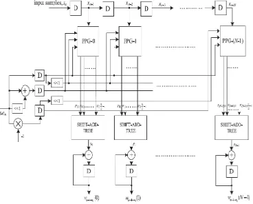
Proposed structure for error computation unit of an N-tap DLMS adaptive filter is shown in Fig. 3. It consists of N number of 2-bit partial product generators (PPG) corresponding to N multipliers and a cluster of L/2 binary adder trees, followed by a single shift–add tree. Each subblock is described in detail.
Fig.3 structure of error-computation block
i)Structure of PPG:The structure of each partial product generator (PPG) is shown in Fig.4.It consists of L/2 number of 2-to-3 decoders and the equal number of AND/OR cells(AOC) Each of the 2-to-3 decoders takes a 2-bit digit (u1u0) as input and produces three outputs b0=u0.u1, b1=u0·u1,and b2=u0·u1, such that b0=1 for (u1u0)=1, b1=1 for(u1u0)=2, and b2=1 for (u1u0)=3. The decoder output b0,b1 and b2 along with w, 2w, and 3w are given to an AOC,where w, 2w, and 3w are in 2’s complement representation and sign-extended to have (W+2) bits each.
Fig.4 structure of partial product generator
Available Online at www.ijpret.com 277
all the n bits of input D to its n AND gates as one of th e inputs. The other inputs of all the n AND gates are fed with the single-bit input b.The output of an AOC is w, 2w, and 3w corresponding to the decimal values 1, 2, and 3 of the 2-b input (u1u0). The decoder along with the AOC performs 2-bit multiplicati on and L/2 parallel multiplications with a 2-bit digit to produce L/2 partial products of the product word.
iii)Structure of Adder Tree:The shifts-add operation on the partial products of each PPG gives the product value and then added all the N product values to compute the inner product output. However, the shift-add operation obtains the product value which increases the word length, and the adder size. To avoid increase in word size of the adders, we add all the Npartial products of the same place value from all the N PPGs by a single adder tree. Table I shows the pipeline latches for various filter lengths.
B. weight-update block
Available Online at www.ijpret.com 278 Fig.5 structure of weight-update block
C. Fixed-point considerations
The fixed-point implementation of the proposed DLMS adaptive filter shows the bit level pruning of the adder tree, to reduce the hardware complexity without the degradation of steady state MSE. For fixed-point implementation, the word lengths and radix points for input samples, weights, and internal signals are need to be decided. Fig. 6 shows the fixed-point representation of a binary number. Table II shows the fixed-representation of the desired signals; its quantization is usually given as an input. For this purpose, the specific scaling/sign extension and truncation/zero padding are required. Since the LMS algorithm performs learning so that y has the same sign as d, the error signal e can also be set to have the same representation as y without overflow after the subtraction.
Fig.6 fixed-point representation of a binary number
Available Online at www.ijpret.com 279 4. ADDER TREE OPTIMIZATION
The adder tree and shift–add tree computation can be pruned for further optimization of area, delay, and power complexity. The adder tree structure is given in fig.7. To reduce the computational complexity, some of the LSBs of inputs of the adder tree can be truncated and the guard bits can be used to minimize the impact of truncation on the error performance of the adaptive filter. To have more hardware saving, the bits to be truncated are not generated by the PPGs, so the complexity of PPGs also gets reduced. To have more hardware saving, the bits to be truncated are not generated by the PPGs, so the complexity of PPGs also gets reduced.
Fig.7 structure of adder tree
5. SIMULATION RESULTS
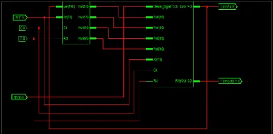
The Simulation results are carried out for Fixed-point LMS adaptive filter to find out the low adaptation delay. The Simulation is carried out by the Model sim 6.3f as a simulator tool. The performance of the delay block is simulated by giving various inputs to the weight-update block with various weights is given below. The error can be estimated from the various iterations which are shown below. The Simulation Model & its waveform for delay with its weights w1, w2, w3, w4 is given below in fig 8.
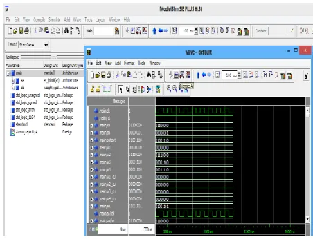
Available Online at www.ijpret.com 280 Fig 9: simulation model for delay with Xn=10101010,Dn=00001111, Rst=1 And Clk=1
The Simulation Model & its waveform for delay with its weights w1, w2, w3, w4 is given below in fig 9.
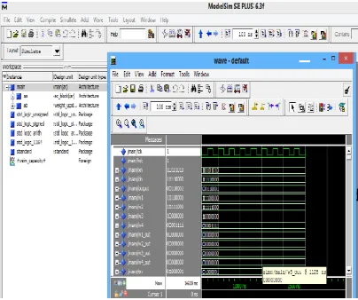
Fig 10: simulation model for delay with Xn=01100000,Dn=00000001, Rst=1 And Clk=1
Available Online at www.ijpret.com 281 Fig 11: simulation model for delay with Xn=10101010,Dn=11110000, Rst=1 And Clk=1
6. CONCLUSION
We proposed an area–delay-power efficient low adaptation delay architecture for fixed-point implementation of LMS adaptive filter. We used a novel PPG for efficient implementation of general multiplications and inner-product computation by common sub expression sharing. Besides, we have proposed an efficient addition scheme for inner-product computation to reduce the adaptation delay significantly in order to achieve faster convergence performance and to reduce the critical path to support high input-sampling rates. Aside from this, we proposed a strategy for optimized balanced pipelining across the time-consuming blocks of the structure to reduce the adaptation delay and power consumption, as well. The proposed structure involved significantly less adaptation delay and provided significant saving of ADP and EDP compared to the existing structures.
REFERENCES
1. B. Widrow and S. D. Stearns, Adaptive Signal Processing. Englewood Cliffs, NJ, USA:
Prentice-Hall, 1985.
2. S. Haykin and B. Widrow, Least-Mean-Square Adaptive Filters. Hoboken, NJ, USA: Wiley,
2003.
3. M. D. Meyer and D. P. Agrawal, “A modular pipelined implementation of a delayed LMS
transversal adaptive filter,” in Proc. IEEE Int. Symp. Circuits Syst., May 1990, pp. 1943–1946.
4. G. Long, F. Ling, and J. G. Proakis, “The LMS algorithm with delayed coefficient adaptation,”
Available Online at www.ijpret.com 282
5. G. Long, F. Ling, and J. G. Proakis, “Corrections to ‘The LMS algorithm with delayed
coefficient adaptation’,” IEEE Trans. Signal Process., vol. 40, no. 1, pp. 230–232, Jan. 1992.
6. H. Herzberg and R. Haimi-Cohen, “A systolic array realization of an LMS adaptive filter and