Available Online at www.ijpret.com 243
INTERNATIONAL JOURNAL OF PURE AND
APPLIED RESEARCH IN ENGINEERING AND
TECHNOLOGY
A PATH FOR HORIZING YOUR INNOVATIVE WORK
MITIGATION OF POWER QUALITY ISSUES
RAJSHREE DESHMUKH1, NAVAL DAMLE2
1. P.G. Department of Electrical Engg, AbhaGaikwad Patil College of Engineering, Nagpur (M.S)India
2. P.G. Department of Electrical Engg, Assistanst Professor, Tulsiramji Gaikwad Patil College of Engineering, Nagpur (M.S),India
Accepted Date: 05/03/2015; Published Date: 01/05/2015
\
Abstract:Mainly the power quality problems are - active power, reactive power, variation in voltage, flicker and harmonic contents. Electric power quality relates to non-standard voltage, current or frequency that results in failure of consumer end equipment or malfunctioning of equipments. The power quality can affect the performance of the electrical equipments; the electrical equipments may have to be derated for the poor power quality. Further, sensitive loads like PLCs, adjustable speed drives may trip leading to financial and time losses to the industry. This paper gives the power quality issues, their effects and consequences on the electrical equipments and the methods to reduce them.
Keywords: Electric Power Quality, Power Quality Effects, Mitigation, Flexible AC Transmission System devices.
Corresponding Author: MS. RAJSHREE DESHMUKH
Access Online On:
www.ijpret.com
How to Cite This Article:
Rajshree Deshmukh, IJPRET, 2015; Volume 3 (9): 243-257
Available Online at www.ijpret.com 244
INTRODUCTION
Power Quality is defined as power that enables the equipment to work properly. A power quality problem can be defined as any deviation of magnitude, frequency, or purity from the ideal sinusoidal voltage waveform. Good power quality is benefit to the operation of electrical equipment, but poor power quality will produce great harm to the power system [2]. Harmonics are defined as sinusoidal waveform having a frequency equal to an integer multiple of the power system fundamental frequency. It is a component of a periodic waveform. If the fundamental frequency multiple is not an integer, then we are dealing with interharmonics [2].
What do we mean by ‘power quality’? A perfect power supply would be one that is always available within voltage and frequency tolerances, and has a pure noise free sinusoidal wave shape. The Power Quality area is very broad and it has many branches that deal with different problems and issues. Any device to be connected to the electric grid has to fulfil standardized power quality requirements. This is to ensure that the electric grid is protected from unacceptable disturbances. The connected device, therefore, is connected to the grid with electric quantities within guaranteed limits [1].
Modern electronic equipments and devices, such as microprocessors, microcontrollers, tele-communications equipment and sensitive computerized equipments etc. are generally responsible to PQ problems. A poor PQ has become a more important issue for both power suppliers and customers. Poor power quality means there is a deviation in the power supply to cause equipment misoperation or may failure.
Table I shows power quality defects, which are fall into five categories and their main possible causes [1].
Table 1. POWER QUALITY DEFECTS AND THEIR MAIN POSSIBLE CAUSE
Type Power Quality Defects Main Possible Causes
1 Harmonic distortion Arising within the customer’s own installation and
may or may not propagate onto the network
2 Blackouts Caused by the supplier but can also by the failure of
on-site equipment, conductors and connections.
3 Under or over voltage Caused by fluctuation of the supply voltage, typically
due to the use of large fluctuating loads (flicker).
4 Dips (or sags) and surges The responsibility of the supplier
Available Online at www.ijpret.com 245
5 Transients Switching or lightning strikes on the network and switching of reactive loads on the consumer’s site or on the same circuit.
POWER QUALITY ISSUES & ITS CONSEQUENCES
Perfect power quality means that the voltage is continuous and sinusoidal having constant figures of amplitude and frequency. Power quality can be expressed in terms of physical characteristics and properties of electricity. It is most often described in terms of voltage, frequency and interruptions [3].
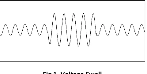
A. Voltage Swell
This is a short term increase in voltage for a few cycles duration. voltage swell is an increase in RMS voltage as shown in fig.1 in range of 1.1p.u to 1.8p.u for duration greater than half cycle and less than 1 minute.
Swells are usually associated with system fault conditions, but they are much less common than voltage sags. A swell can occur due to a single line-to-ground fault on the system which can result temporary voltage rise on the other unfaulted phases. Swells can also be caused by switching off a large load or switching on a large capacitor bank. Voltage swells can put stress on computer and many home appliances. It also causes tripping of protective circuit of an adjustable speed drive [4].
Fig 1. Voltage Swell
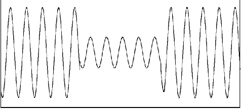
B. Voltage Sag
Available Online at www.ijpret.com 246
Fig 2. Voltage Sag/Dip
Voltage sags are related to with system faults but it also caused by switching of heavy loads like transformer, circuit breaker or starting of large motors. Voltage sag can cause loss of production in automated process since a voltage sag trip a motor or cause its controller to malfunction, namely microprocessor based control system, programmable logic controller, adjustable speed drives, that may lead to a process stoppage, tripping of contractors and loss of efficiency of electric machine.Impact of long duration variation is greater than those of short duration variation [5].
C.Short Interruption
Short interruption causes tripping of protection device, stoppage of sensitive equipments like personal computer, programmable logic controller[5].
It is total interruption of electric supply for duration from few milliseconds to 1 or 2 sec. It causes due to mainly opening and automatic closing of protective devices.
D.Long Interruption
It is total interruption of electric supply for duration of 1-2 seconds. It causes due to equipment failure in power system and failure of protection equipments [5].
Available Online at www.ijpret.com 247 Interruptions can results the power system faults, equipment failure, and control system malfunction. The interruptions are always less than 10% of nominal supply voltage. The duration of an interruption due to equipment malfunctions or loose connections can be irregular. Ninety percent of fault on overhead distribution lines are of temporary nature. Basically, these faults are due to lightning or tree limbs or animals causing grounded.
A temporary interruption lasting a few seconds can cause a loss of production, erasing of computer data etc. The cost of such an interruption during peak hours can be very heavy [4].
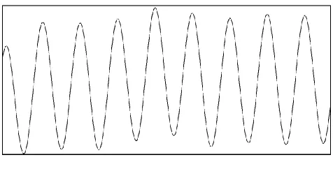
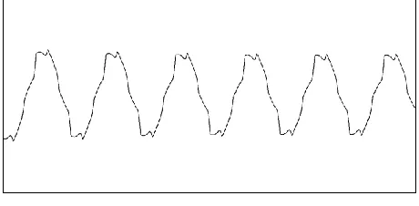
E. Voltage Flicker
Flicker is defined as the “Impression of fluctuating brightness or colour, occurring when the frequency of observed variation lies between a few Hertz and the fusion frequency of images”. Flicker comes due to rapid on-off of incandescent and fluorescent lamps. It results rapid variation in voltage due to fast changes in load as shown in fig.4.
Fig 4. Voltage Flicker
Flicker can occur due to electric arc furnaces, wielding machines, large ASD with inadequate DC-link filtering system. Voltage flickers are caused by arc discharge lamps, arc furnaces, starting of large motor, arc welding machines etc. Flicker has adverse effects on human health due to the high frequency flickering of light bulbs, fluorescent tubes or television screen can cause stress on the eyes resulting in headache. The flicker can also reduce the life of electronic equipments like lamps, television, radioetc [4].
F. Voltage Unbalance
Available Online at www.ijpret.com 248 or zero sequence components to the positive sequence component. The negative or zero sequence voltages in a power system generally results from unbalanced loads causing negative or zero sequence currents to flow in the system. Voltage imbalance can cause temperature rise in motors and can even cause a large motor to trip [4].
Fig 5. Voltage Unbalance
G.Harmonics
It is a sinusoidal component of a periodic wave having a frequency that is an integral multiple of the fundamental frequency as shown in fig.6. Harmonics can be considered as voltages or current present on an electrical system at some multiple of the fundamental frequency.
Fig 6. Voltage Harmonics
Available Online at www.ijpret.com 249
Table 2. VOLTAGE HARMONICS LIMITS
System Voltage (KV) Total harmonic Distortion (%)
400 2.0
220 2.5
132 3.0
The voltage variation, sag, swell, harmonics causes malfunctioning of electronics equipments namely microprocessor based system, programmable logic controller, adjustable speed drives etc. Due to all this problems it may cause tripping of contractors, protection devices, also stoppage of sensitive equipments like computer, programmable logic control system and may be damage the sensitive equipments. Due to all this problems the whole system will be derated.
POWER QUALITY MITIGATION TECHNIQUES
The different technologies are available for power quality mitigation based on the system requirement are given below:
(1) Reactive power compensation technologies:
(a) Active Filters
(b) Dynamic voltage restores (DVR)
(c) Static VAR compensator (SVC)
(d) Static synchronous compensator (STATCOM)
(e) Static synchronous series compensator (SSSC)
(f) Synchronous condenser
(g) Unified power flow controller (UPFC)
(h) Interline power flow controller (IPFC)
(2) Constant Voltage transformer
(3) Magnetic Synthesizers
Available Online at www.ijpret.com 250 (5) Flywheel Energy storage system
As discussed the poor power quality affects the system parameters and also end user equipments. So to compensate reactive power and to improve power quality FACTS devices are introduced. Voltage support at a load can be achieved by reactive power injection at the load point of common coupling. Flexible AC Transmission Systems, called FACTS, is very popular which can improve system performance by means of power electronic devices. FACTS devices inject a current into the system to correct the voltage sag and swell. Several FACTS-devices have been already introduced for various applications in worldwide [6]. The basic applications of FACTS-devices are: Power flow control, Increase of transmission capability, Voltage control, Reactive power compensation, Stability improvement, Power quality improvement, Power conditioning, Flicker mitigation [6]. The introduction of FACTS-devices is achieved through switched or controlled shunt compensation, series compensation or phase shift control. The devices are used for current, voltage or impedance controllers. As stated above different techniques for power quality improvement out of this some reactive power compensation techniques are explained in details.
A. Active Filters
A flexible and popular solution for power quality related problems is active power filters. Mainly the active filters are connected to low and medium voltage system either in series or in shunt. Series active filter must operate in co-ordination with shunt passive filters to reduce and compensate load side current harmonics. Shunt active filters are operating as a current source and series active filters are operates as a voltage source [7].
Available Online at www.ijpret.com 251
iS V iL
AF
AF
Vd AC Source
Fig 7. Series Active Filter
The high impedance imposed by the series active power filter is created by generating a voltage of the same frequencythat the current harmonic component that needs to be eliminated. Voltage unbalance is corrected by compensating the fundamental frequency negative and zero sequence voltage components of the system [7].
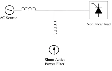
2) Shunt Active Filter: Shunt active filters compensate the load side current harmonics by injecting equal-but- opposite harmonic compensating current in the system.
Non linear load
Shunt Active Power Filter AC Source
Fig 8. Shunt Active Filter
In this system the shunt active filter operates as a current source that is phase shifted by 180o and it can inject the harmonic components developed by the load. The current compensation block diagram of the shunt active filter is shown in Fig.8 [7].
Available Online at www.ijpret.com 252 B. Dynamic Voltage Restorer
During voltage dip shunt connected VSC boost the voltage at that point by injecting current in the point of connection. Also by injecting voltage into the grid with series connected VSC we can mitigate the voltage dips. The injected voltage adds the supply voltage during the voltage dip, and restores the load voltage to its normal value. Both in shunt and series configuration, the VSC must be controlled properly to inject the necessary current or voltage into the grid to compensate voltage dip.
The block diagram of DVR is shown in fig.9. it represents the Thevenin equivalent circuit. The impedance Zth depends on the fault level of the load side bus [3]. The main functions of DVR are reactive power compensation, voltage regulation, compensation of voltage sag and swell and unbalance voltage compensation for three phase system.The VSC generates a three phase ac output voltage which is controllable in phase andmagnitude. These voltages are injected into the ac distribution system in order to maintain theload voltage at the desired voltage reference.
Voltage source converter
Energy storage Vsh
Rth jXth
P+jQ Ish
DVR
Fig 9. Block Diagram of DVR
C. Static VAR Compensator
Electrical loads both generate and absorb reactive power. Since the transmitted load varies considerably from one hour to another, thereby the reactive power balance in a grid varies. The result can be unacceptable voltage variations or even a voltage depression and at the extreme a voltage collapse. A rapidly operating Static Var Compensator (SVC) can continuously provide the reactive power required to control dynamic voltage oscillations under various system conditions and thereby improve the power system transmission and distribution stability.
Available Online at www.ijpret.com 253 under different network conditions. In addition, an SVC can mitigate active power oscillations through voltage amplitude modulation[9].In industrial applications, SVCs are placed where rapidly varying loads and at high load sides such as arc furnaces, where they can smooth flicker voltage.The main advantage of SVCs over
Simple mechanically-switched compensation schemes is their near-instantaneous response to changes in the system voltage [9].
Grid Connection
Step down Transformer
Mechanically Switched Reactor
Harmonic Filter
Mechanically Switched Capacitor
Fig 10. Block Diagram of SVC
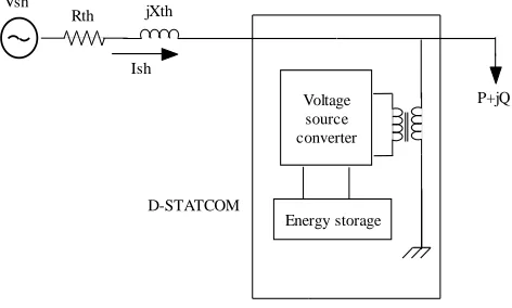
D. STATCOM
Available Online at www.ijpret.com 254 A STATCOM consists of a three phase inverter (generally a PWM inverter) using SCRs, MOSFETs or IGBTs, a D.C capacitor which provides the D.C voltage for the inverter, a link reactor which links the inverter output to the a.c supply side, filter components to filter out the high frequency components due to the PWM inverter. From the d.c. side capacitor, a three phase voltage is generated by the inverter. This is synchronized with the a.c supply. The link inductor links this voltage to the a.c supply side. This is the basic principle of operation of STATCOM [7]. Such configuration allows the device to absorb or generate controllable active and reactive power.
Voltage source converter
Energy storage D-STATCOM
Vsh
Rth jXth
P+jQ Ish
Fig 11. Block Diagram of STATCOM
1) Advantages of STATCOM over SVC, DVR: There are so many advantages of STATCOM over
SVC and DVR and other FACTS devices.
The STATCOM provides better damping characteristics than the SVC and DVR as it is able to exchange active power with the system.
The reactive power provided by STATCOM is independent of the actual voltage on the connection point of STATCOM.
STATCOM have almost the same impact on the system behavior as long as they operate within their control ranges.
The STATCOM is more robust and effective than an SVC in providing voltage support and stability improvements.
Available Online at www.ijpret.com 255 A STATCOM can improve power-system performance in such areas as the following:
The transient stability;
The voltage flicker control; and
It also controls real power in line when it is needed
The dynamic voltage control in Transmission and distribution systems;
The power-oscillation damping in power transmission systems;
H.
2) Application of STATCOM: STATCOM has the following applications in power system.
Improvement of steady-state power transfer capacity
Reduction of temporary over-voltages developed in power system.
To damp the oscillations developed in power system
Load balancing of individual phases.
Reactive compensation of AC-DC converters and HVDC links.
I.
Effective voltages regulation and control.
Reduction of rapid voltages fluctuations (flicker control) [10].
CONCLUSION
Available Online at www.ijpret.com 256 consequences on the consumer, electric utilityalong with various mitigation techniques to improve the power quality.
FUTURE SCOPE
Demand for power is always increasing day by day. The power quality problems are also following the same trend and increasing day by day. So there is need to reduce such power quality problems and make the supply system efficient. FACT devices can be controlled through different techniques to get better coordination between real and reactive power.
STATCOM is one of the promising technologies to overcome the power quality problems. The power quality can be still improved by using soft computing techniques like Unified power flow controller.
REFERENCES
1. Lu Yan: “Wind Power Generation related power quality Issues” 2010
2. E. Srinivas, M. Rama Sekhara Reddy, “Power Quality Improvement in Grid Connected Wind Energy System Using Facts Device and PID Controller” IOSR Journal of Engineering, Volume 2, Issue 11 (November 2012), PP 19-26
3. Johnson Abraham Mundackal, Sreekala P. “Grid Power Quality Improvement and Battery Energy Storage in Wind Energy Systems” International Conference on Microelectronics, Communication and Renewable Energy (2013).
4. Guriqbal Singh, “Electric Power Quality-Issues, Effects and its Mitigation” International Journal of Engineering Research & Technology (IJERT) ISSN: 2278-0181, Vol. 2 Issue 6, June - 2013.
5. M.P. P´alsson, K. Uhlen, J.O.G. Tande. “Large-scale Wind Power Integration and Voltage Stability Limits in Regional Networks”; IEEE 2002.p.p. 762–769
6. M. A. Abido “Power System Stability Enhancement Using Facts Controllers” A REVIEW
7. Luis A. Moran, Juan W. Dixon. Jose R. Espinoza, Rogel R. Wallace, “Using Active Power Filters To Improve Power Quality”.
Available Online at www.ijpret.com 257 Based on Sinusoidal Pulse Width Modulation (SPWM)”, IEEE- International Conference On Advances In Engineering, Science And Management (ICAESM -2012) March 30, 31,2012 436.
9. Jyothilal Nayak Bharothu, K Lalitha, “Compensation of voltage flicker by using facts devices” American Journal of Electrical Power and Energy Systems 2013; 2 (3) : 66-80Published online May 30,2013.
10.Dae-Wook Kang, Woo-Chol Lee, Dong-Seok Hyun “The Distribution STATCOM for Reducing the Effect of Voltage Sag and Swell”, Department of Electrical Engineering, HanYang University, Haeng Dang Dong, SungDong GU ,SEOUL 133-791