ISSN : 2581-7175 ©IJSRED: All Rights are Reserved
Page 901
Ultrasonic Pulse Velocity Assessment of
Cement Stabilized Soil
Vinay M*, Vinay A** A V Pradeep Kumar***
*Department of civil engineering,Dayananda Sagar College of Engineering, Bengaluru, 560078, India
vinaymath6@gmail.com
**Department of civil engineering,Dayananda Sagar College of Engineering, Bengaluru, 560078, India
vinay.a.9333@gmail.com
***
Department of civil engineering, Jawaharlal Nehru National College of Engineering, Shivamogga, India pradeepavku@yahoo.co.uk---
************************
---Abstract:
Black cotton soil which is one of the major soil deposits which accounts for more than 50% of soil in India and is highly problematic because of its property of higher degree of swelling and shrinkage. These soils are used in sub grade of pavement and also in construction of structures. Hence in order to improve the properties of such soils many methods are available like soil stabilization, soil replacement, moisture control etc. In recent years, soil stabilization by using various minerals like quarry dust, saw dust, copper dust, cement and fly ash were most commonly used. In the present study cement is used as admixture and NDT was performed on clayey soil compacted by rolling compactor cum rut analyzer. The experiment was conducted with varying proportions of cement and the relation between maximum dry density, moisture content, pulse velocity etc were determined. lab test specimens were prepared and wave velocity was measured for each of the compacted stabilized specimen. in this paper the Maximum dry density of the soil is related with the obtained velocity and thus real time density is obtained in field by simple ultrasonic pulse velocity test.
Keywords
—
cement, maximum dry density, water content, optimum moisture content, ultrasonic pulse
velocity etc
---
************************
---I.
INTRODUCTIONClay soils are compacted for construction of various structures and facilities. Compacted clay soils are commonly used as liners for waste containment facilities; as embankments, sub grade, bases, and backfills for foundations. Compaction characteristics of soils are determined by analyzing the relationship between water content and dry density (unit weight) of soils. Proctor compaction tests (ASTM D 698) are commonly used in the laboratory to determine the variation of dry density with water content. The relationship between dry density and water content of soils is demonstrated using a compaction curve. Compaction
properties of field soils are compared with the compaction properties of the soils determined in the laboratory to verify the effectiveness of construction procedures.
In-situ method is used in the field it is consuming more time. To reduce this time this research paper aims to introduce the ultra-sonic pulse velocity method as an alternative method. Ultrasonic testing can provide a fast and simple approach for determining characteristics of compacted clayey soils. This non-destructive method can be used as an alternative to existing methods to analyze laboratory or field compacted soils.
Soils having various plasticity like clayey soil have been tested using conventional tests and then performed with
ISSN : 2581-7175 ©IJSRED: All Rights are Reserved
Page 902
ultrasonic pulse velocity test on these samples & prepared thegraph; water content v/s velocity, density v/s velocity. Then relationship was found by interpolating the results from the former conventional tests & ultrasonic pulse velocity test concluded the results. As the laboratory tests are conducted the standard values are obtained then & cross check with the laboratory ultrasonic pulse velocity result then results are concluded.
II.
SCOPEANDOBJECTIVESOFPRESENTSTUDYThe aim of the research is to evaluate the physical property of Clayey soil and stabilization of Clayey soil by cement, using ultrasonic testing method which can used as alternative to conventional in-situ testing method.
To study the effects of cement on the engineering performance of Clayey soil and to verify if it can used as soil stabilizer for soil sub grade in Highway pavements.
1.Volume stability - to control the swell-shrink characteristics caused by moisture changes.
2.Durability - to increase the resistance to erosion, weathering or traffic loading.
3.Cement increase sub grade strength, stiffness and reduce the volumetric expansion tendencies
4.To analyze Variation in ultrasonic velocity with water content and density of compacted soils.
5. Non-destructive evaluation of materials and structures by Ultrasonic instrument.
6. This investigation was conducted to assess the feasibility of using ultrasonic testing (in this case ultrasonic velocity measurements) to determine compaction characteristics of Clayey soils.
III.
METHODOLOGYThe soil was excavated from a depth of 1.5 m from the natural ground level and soil was pulverized with Rammer to break lumps and then cement was used for mixing with clayey soil. A number of clayey soil and cement combinations were used to determine the compaction and strength properties of mixes in accordance with IS, compaction and strength properties of mixes were evaluated in the laboratory. The ultrasonic tests conducted for this study consisted of determination of velocity of P-waves in the test compacted stabilized soil using two transducer arrangements one for transmitting and another for receiving for wave as shown in figure. The tests were conducted using Through Transmission or Direct Transmission.
A. Ultrasonic pulse velocity Test
The investigation to use of ultrasonic methods to determine compaction characteristics of clayey soils were conducted. The transmission tests method was conducted to determine P-wave velocities in compacted clayey soils. Effects on velocity due to soil type and compaction conditions were investigated.
Ultrasonic testing is used for non destructive evaluation of materials and structures (Sologyan, A. I. 1990). Ultrasonic waves are stress waves with frequencies higher than 20 kHz that propagate in mass media. Propagation of ultrasonic waves in a material is affected by the properties and condition of the material. Transmission of waves in a material is quantified generally using two parameters: velocity and attenuation. Ultrasonic velocity can be correlated to elastic constants and mechanical properties of a material, whereas ultrasonic attenuation can be correlated to micro structural properties of a material (McIntire 1991).
B. About the Equipment
The electronic equipment used for velocity measurements consists of three units:
1. P-wave transducers, 2. Pulse-receiver, and 3. Data acquisition system
Two transducers are used for measurements, one transducer for transmitting ultrasonic waves, the other for receiving ultrasonic waves that travel through the test sample. The transducers are actuated by a pulse receiver which is connected to the data acquisition system for digitization of data. The soil stabilized with the Cement with increasing percentage 0%, 2%, 4% ,6%, 8%, 10% are compacted with varying water content using rolling compactor cum rut analyser .The compacted soil mass is subjected to the ultrasonic pulse velocity test. The velocities are recorded and graps for the respective parameters were plotted
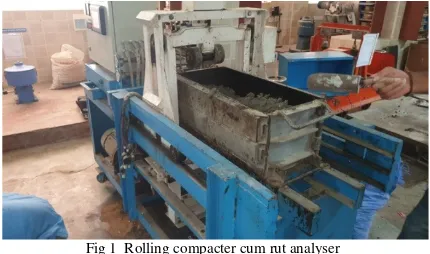
C. Rolling compactor cum rut analyser
Rolling compacter cum rut analyser is generally used as an alternative compactor for Bituminous Mix and in this experiment the compactor is used to compact the soil mix.
Fig 1 Rolling compacter cum rut analyser
ISSN : 2581-7175 ©IJSRED: All Rights are Reserved
Page 903
drum or any other attachments. The passes determine the typeof compaction required, more the passes more will be the compaction. Depending upon the nature of work the equipment can be used accordingly.
IV.DATA ACQUISTION
The black cotton soil is mixed with cement in varying percentages from 2 to 10%. OMC and MDD is found out for the the respective cement percentages.The specimens are Prepared by applying load and compacting it with rolling compactor cum rut analyser. Further the ultra sonic pulse velocity test is conducted on the specimen and velocities are determined. Also time is noted for the corresponding velocities. table 2 shows the velocities and table 3 and 4 shows the time for direct and indirect transmission respectively. In table 4 the time for indirect transmission at 125, 250, 375 and 500 mm are tabulated.
TABLE 1
PHYSICAL PROPERTY OF BLACK COTTON SOIL
Sl no Property/ parameter value
1. Specific gravity 2.22
2. Grain size analysis( soil type) Well graded 3. Atterberg‟s limits
Liquid limit% 36.53
Plastic limit 26.78
4. Plasticity index 9.75
5. Free swell 11.11
6. Compaction characterstics
Max dry density(kN/m^3) 1.77
Optimum moisture content(omc)%
14
7. Hydrometer analysis
% of sand 74
% of silt 24
% of clay 2
.
Table 2. velocity table Cem ent % OM CMDD Velocity( m/s) For SPT specimen Velocity (m/s) For slab (Direct transmissi on) Velocity (m/s) For slab (indirect transmissio n)
0 20 1.67 615 584.25 525.83
2 22 1.77 1683 1565.19 1346.07
4 22 1.78 1567.9 1426.789 1284.12
6 22 1.78 1602 1473.84 1296.98
8 22 1.79 1683 1632.51 1469.26
10 22 1.8 1747 1642.18 1477.97
Table 3.
Direct transimission time in micro seconds
Table 4.
Indirect transmission time in micro seconds
Time(125 mm) Time(250 mm) Time(375 mm) Time(500 mm)
375.29 750.57 1125.86 1501.14
109.17 215.81 323.71 421.45
105.54 211.08 316.62 422.16
107.47 217.37 318.73 429.86
117.93 235.86 353.79 471.72
123.71 247.41 371.12 494.82
Graph 1. cement vs omc
19 19.5 20 20.5 21 21.5 22 22.5
0 2 4 6 8 1 0
CEMENT% VS OMC
Time (spt specimen)
Time ( slab at 150 mm)
Time ( slab 650 mm)
447 500.38 2168.32
139 152.33 660.1
129.8 140.72 609.79
132.3 146.54 635.01
139 157.24 681.38
ISSN : 2581-7175 ©IJSRED: All Rights are Reserved
Page 904
Graph 2. cement vs Mdd
Graph 3. cement vs velocity
Graph 4 .cement vs direct time
Graph 5.Indirect time
V.RESULTDANDDISCUSSION
In table 1 it is observed that as the density increases the
velocity also increases, this increase in velocity is due to the fact that waves travel faster in denser medium. The graph 1 is plotted for cement vs omc and it is observed that the omc of soil when added with cement stays constant, where as the cement free soil has omc less than the soil -cement mixture. Hence addition of cement surely increases the density of th soil. Graph 2 is plotted for cement vs MDD, here the graph shows that for increase in cement percentage there is increase in density and hence in case of soil-cement mixture density achieved is higher than the soil without cement. therefore the cement surely increase density of the soil. The Graph 3 shows the cement vs velocity plot. Here the velocity increases with increase in cement percentage which indirectly states that the increase in velocity is due to increase in density of soil . From graph 4 it is noted that the time for cement less soil is far more than the other cement-soil mixture ,where the is graph is almost similar for all other percentages of cement. Graph 5 is similar to graph 4 where the indirect transmission time is recorded which varies about 5 to 10%, when compared with direct transmission.VI.CONCLUSIONS
From the obtained analyzed results, the following conclusions were drawn:
1. cement can be used as a stabilizing agent for clayey soil 2. The maximum dry density increased and with increase with cement percentage
3. The velocity of waves increases with increase in cement percentage
4. Durability and volumetric stability also increases with cement percentage.
1.65 1.7 1.75 1.8 1.85
0 5 10 15
CEMENT% VS MDD
0 500 1000 1500 2000
0 5 10 15
CEMENT% Vs VELOCITY
DT-CC
DT-SLAB
IT-SLAB
0 500 1000 1500 2000 2500
0 2 4 6 8 10 12
CEMENT Vs DIRECT TIME
0 500 1000 1500 2000
0 2 4 6 8 10 12
ISSN : 2581-7175 ©IJSRED: All Rights are Reserved
Page 905
REFERENCES
[1] ASTM D 698–91. Test methods for laboratory compaction characteristics of soil using standard effort. Annual Book of ASTM Standards, vol. 4, no.8, PA: ASTM International, West Conshohocken; 1997. p. 77–84.
[2] H. Ziari, H. Behbahani, A. Izadi and H. Divandary: “Field Evaluation of Non – Destructive tests in measuring the Pavement layers Density”.
[3] IS: 2720 (Part 5) – 1985, “Determination of Liquid Limit and Plastic Limit”.
[4] IS: 2720 (Part 3) – 1980, “Determination of Specific Gravity of Fine, Medium and Coarse grained soils”.
[5] IS: 1498 - 1970, “Classification and Identification of Soils for General Engineering Purposes”.
[6] IS: 27200 (Part 40) – 1977, “Determination of Free Swell Index of soils”.
[7] J. M. Raut, S.R.Khadeshwar, S.P.Bajad: “Interrelation of Properties of soil with Ultrasonic Pulse Velocity”. [8] Mcintire, P., (1991). Nondestructive Testing Handbook. Volume Seven Ultrasonic Testing, American Society for Nondestructive Testing, Columbus, OH.
[9] Nazli Yesiller, Gokhan Inci and Carol J. Miller: “Ultrasonic testing for Compacted Clayey soils”.
[10] Sologyan, A. I., (1990). "Survey of Methods and Means for Determining Soil Density in the Field," Soviet Journal of Nondestructive Testing," Plenum Publishing Corp., 25 (7), pp. 480-486.
[11] Suksun Horpibulsuka, Apichat Suddeepong, Pokin Chamketa, Avirut Chinkulkijniwat: “Compaction Behaviour of Fine grained soils, Lateritic soils and Crushed rocks”. [12] Thomas B. Randrup and John M. Lichter: “Measuring soil Compaction on Construction Sites (A review of Surface Nuclear Gauges and Penetrometers)”.