TUNING OF EXCITATION AND TCSC -BASED STABILIZERS
FOR MULTIMACHINE POWER SYSTEM
P. Bera
Department of Electrical Engineering, Marine Engineering and Research Institute W.B. 700088, Kolkata, India
D. Das*and T.K. Basu
Department of Electrical Engineering, Indian Institute of Technology Kharagpur W.B. 721302, Kharagpur, India
[email protected] - [email protected]
*Corresponding Author
(Received: February 3, 2009 – Accepted in Revised Form: November 5, 2009)
Abstract In this paper, tuning of power system stabilizer (PSS) and thyristor controlled series capacitor (TCSC) is studied. The analysis of mode controllability is used to select the effective location for TCSC. The performances of TCSC equipped with a proportional-integral-derivative controller (P-I-D controller) and proportional-integral-derivative power system stabilizer (P-I-D PSS) are investigated. The dynamic responses considering TCSC equipped with a D controller and P-I-D PSS are compared with considering TCSC equipped with a phase lead-lag controller and conventional power system stabilizer (CPSS). The controllers design problem is formulated as an optimization problem. The genetic algorithm (GA) is used to search for optimal settings of controller parameters. Analysis reveals that the TCSC equipped with P-I-D controller and P-I-D PSS give better dynamic performances.
Keywords CPSS, P-I-D PSS, TCSC, Genetic Algorithm (GA)
هﺪﻴﻜﭼ
ارد ﻳ
ﻈﻨﺗ ﻪﻟﺎﻘﻣ ﻦ
ﻴ ﺎﭘ ﻢ ﻳ
ﺳ هﺪﻨﻨﻛ راﺪ
ﻴ
قﺮﺑ ﻢﺘﺴ
(PSS)
ﺮﺳ نزﺎﺧ و
ي هﺪﺷ لﺮﺘﻨﻛ thyristor (TCSC) ﺳرﺮﺑ ﻲ ﻣ ﻲ دﻮﺷ . ﻠﺤﺗزا ﻴ ﻠﺑﺎﻗﻞ ﻴ
اﺮﺑشورلﺮﺘﻨﻛﺖ
ي
اﺮﺑﺐﺳﺎﻨﻣنﺎﻜﻣبﺎﺨﺘﻧا
ي TCSC ﻣهدﺎﻔﺘﺳا ﻲ دﻮﺷ . دﺮﻜﻠﻤﻋ TCSC ﻪﺑﺰﻬﺠﻣ ﻳ
ﺎﭘوهﺪﻨﻨﻛلﺮﺘﻨﻛﻚ
ﻳ
ﺳﺪﻨﻨﻛراﺪ
ﻴ قﺮﺑﻢﺘﺴ P-I-D درﻮﻣ ﺳرﺮﺑ ﻲ ﻣراﺮﻗ ﻲ ﮔ ﻴ دﺮ . دﺦﺳﺎﭘ ﻳ ﻣﺎﻨ ﻴ ﺎﺑﻚ ﻪﺑﻪﺟﻮﺗ TCSC ﻪﺑﺰﻬﺠﻣ ﻳ
هﺪﻨﻨﻛلﺮﺘﻨﻛﻚ
P-I-D
ﺎﭘو ﻳ
ﺳهﺪﻨﻨﻛراﺪ
ﻴ ﻢﺘﺴ
P-I-D
ﻦﺘﻓﺮﮔﺮﻈﻧردﺎﺑ
TCSC
ﻪﺑﺰﻬﺠﻣ
ﻳ
هﺪﻨﻨﻛلﺮﺘﻨﻛﻚ
اراد ي ﻳ
ﮔدﺎﺘﻓاﻮﻠﺟﻚ
ﻲ زﺎﻓ ي ﺎﭘو ﻳ
ﺳهﺪﻨﻨﻛراﺪ
ﻴ
ﺘﻨﺳقﺮﺑﻢﺘﺴ
ﻲ (CPSS) ﺎﻘﻣ ﻳ ﻣﻪﺴ ﻲ دﻮﺷ . ﻞﻜﺸﻣ ﺣاﺮﻃ ﻲ هﺪﻨﻨﻛلﺮﺘﻨﻛ ﻪﺑﺎﻫ ناﻮﻨﻋ ﻳ
ﻬﺑﻞﻜﺸﻣﻚ
ﻴ ﻪﻨ زﺎﺳ ي ﻣﻪﻟﻮﻣﺮﻓ ﻲ دﻮﺷ . رﻮﮕﻟا ﻳ ﺘﻧژﻢﺘ ﻴ ﻚ (GA) اﺮﺑ ي ﻮﺠﺘﺴﺟ ي ﻈﻨﺗ ﻴ ﻬﺑتﺎﻤ ﻴ ﺎﻫﺮﺘﻣارﺎﭘﻪﻨ ي
هﺮﻬﺑدرﻮﻣهﺪﻨﻨﻛلﺮﺘﻨﻛ
رادﺮﺑ ي ﻣراﺮﻗ ﻲ ﮔ ﻴ دﺮ . ﻠﺤﺗ ﻴ ﻞ
ﻣنﺎﺸﻧﺎﻫ
ﻲ
ﻪﻛﺪﻫد
TCSC
ﺰﻬﺠﻣ
ﻪﺑ ﺎﭘوهﺪﻨﻨﻛلﺮﺘﻨﻛ ﻳ
ﺳهﺪﻨﻨﻛراﺪ
ﻴ قﺮﺑﻢﺘﺴ P-I-D ددﺮﻜﻠﻤﻋ ﻳ ﻣﺎﻨ ﻴ ﺮﺘﻬﺑﻚ ي ﻣﻪﺋارا ﻲ ﺪﻫد . 1. INTRODUCTION
Since the 1960s low frequency oscillations have been observed when large power systems are interconnected by relatively weak tie-lines. These oscillations may sustain and grow to cause system separation, if no adequate damping of electromechanical modes is provided.
Several approaches have been reported in the literature to provide the damping torque required for damping machine oscillations. DeMello and
suffer a drawback of being liable to cause a great variations in the voltage profile and may even result in leading power factor operation under severe disturbance condition [2]. Recent advances in power electronics have led to the development of the flexible alternating current transmission system (FACTS). FACTS are designed to enhance power system stability by using reliable and high speed electronics devices. One of the promising FACTS devices is thyristor controlled series capacitor (TCSC) and has found application in improving power system dynamic stability.
Chen, et al [8] have used thyristor controlled series capacitor to increase the damping of dynamic oscillations of the power system. They have considered pole placement technique for computing the controller feedback gains of thyristor controlled series capacitor (TCSC). Thyristor controlled series capacitor (TCSC) with different control schemes have been suggested in [9-10]. Chang, et al [11] have used a time-optimal control to damp inter-area modes in multimachine systems. Rouco, et al [12] have presented tools and methods to study the application of TCSC for damping power system electromechanical oscillations based on eigenvalue sensitivity approach. Yang, et al [13] have used residue method together with modal sensitivities for TCSC to determine location, feedback signal and controller parameters. Tso, et al [14] have used a nonlinear design technique to deduce the control law for TCSC and SVC where SVC is treated as supplement of TCSC. Li, et al [15] have suggested a method to incorporate the analysis of the electromagnetic transient process of TCSC into the power system stability analysis. Son, et al [16] have used LQG (Linear Quadratic Gaussian) technique to the design of the robust TCSC controller for power system oscillation damping enhancement. They have also discussed the pitfalls in applying the LTR (Loop Transfer Recovery) technique to reserve the robustness of the LQG damping controller. Fan, et al [17] have proposed a method to identify an effective local signal for TCSC as a supplementary controller to dampen inter-area oscillations for power system. Ishimura, et al [18] have proposed a design method for the robust TCSC controllers for capacitive reactance in a power system. Del Rosso, et al [19] have proposed a novel hierarchical control designed for both dynamic and steady state stability enhancement for TCSC.
Chen, et al [20] have studied the application of series compensator to improve the stability margin of power system. They have proposed state feedback controller using a linearized system model. Wang, et al [21] have designed a TCSC based stabilizer which is not only avail to damp to target inter-area oscillation mode effectively but also imposes a positive interaction with a PSS in the power system to damp a local oscillation mode. Design of various types of controllers for TCSC have been proposed in [22-24]. Chaturvedi, et al [25] have used generalized neuron based PSS to improved the stability and dynamic performance of a multi-machine power system.
In the present work, the effect of excitation and TCSC control problem are investigated for a multimachine power system. TCSC is very effective for the enhancement of both small disturbance and transient stability. In order to reach this goal, it is necessary to choose a suitable location of TCSC and to adopt an effective control strategy. This work deals with the series capacitor controller design and location of TCSC has been selected by modal controllability analysis [8]. Controller design problem is formulated as an optimization problem. Genetic algorithm is employed to solve this problem with the aim of getting the optimal or near optimal settings of the controller parameters.
2. SYSTEM INVESTIGATED
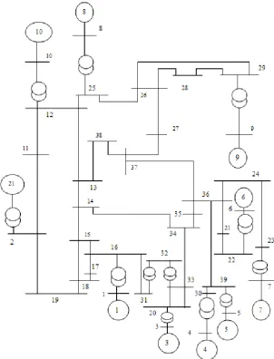
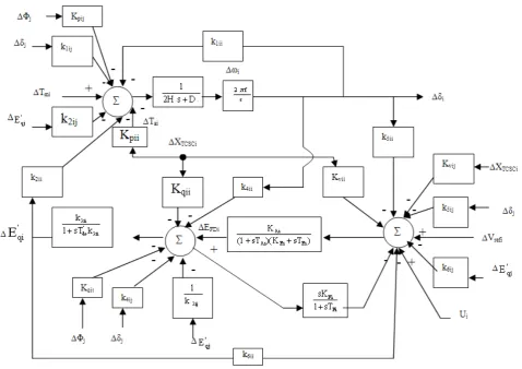
In the present work, a ten machine thirty nine bus system as given in Figure 1 is considered. Data for ten machine thirty nine bus system are taken from [26]. All the machines are equipped with IEEE Type-I exciter. Figure 2 shows the generalized model of multimachine system with TCSC. The model of TCSC as shown in Figure 1, is extensively discussed in [21] where a linearized model is also derived.
3. SELECTION OF PSS LOCATION FOR MULTIMACHINE SYSTEM
used for the selection of PSS location. The participation factors are computed using right and left eigenvectors of the system matrix of the power system. The appropriate definition and determination as to which state variables significantly participate in the selected modes become very important. Verghese, et al [27] have suggested a related but dimensionless measure of state variable participation called participation factor. The participation factor qki is defined as [27]:
ki w n
1 k ki
v ki w ki v ki q
=
= (1)
Where,
qki = participation factor relating to kth state
variable to the ith eigenvalue.
vki = kth entries in the right eigenvector
associated with the ith eigenvalue.
wki = kth entries in the left eigenvector
associated with the ith eigenvalue.
the present work only one machine has been selected for stabilizer placement based on the lowest damping factor and corresponding participation factor. From Table 2, it is seen that machine-4 has highest participation factor in mode 1 and from Table 1, it is seen that in mode 1, damping is the lowest and hence machine 4 is selected for stabilizer location.
4. SELECTION OF TCSC LOCATION FOR MULTIMACHINE SYSTEM
In the present work, the concept of mode controllability analysis [8] has been carried out to determine the most effective location for TCSC. If a single TCSC is considered in the power system, the natural modes present in the system can be
seen in the response of any selected output variable in different proportion when the system is excited by an external stimulation via the control input. In general, for a system with n dynamic modes, the Laplace transform of any selected output variable Y(s) can be shown to be related to the Laplace transform of the input U(s) by
) s ( U n s
n R ... 1 s
1 R (s)
Y
λ − + + λ −
= (2)
Where λ1,…., λnare the eigenvalues of the system
and the R1,…., Rn are the corresponding residues.
The impulse response of the output y(t) is given by
=
λ −
= n
1 i
t i e i R (t)
y (3)
TABLE 1. Electromechanical Mode Eigenvalues and Damping Factor.
Electromechanical Mode Eigenvalues Damping Factor Mode 1 Mode 2 Mode 3 Mode 4 Mode 5 Mode 6 Mode 7 Mode 8 Mode 9
-0.0039 ± j7.3248 -0.1944 ± j6.6865 -0.2469 ± j7.1199 -0.3492 ± j6.2590 -0.4068 ± j8.4989 -0.5682 ± j3.5178 -0.7819 ± j7.4455 -0.8870 ± j9.2709 -1.1355 ± j6.7419
0.0005328 0.0291 0.0347 0.0557 0.0478 0.1595 0.1044 0.0952 0.1661
TABLE 2. Participation Factors.
M/c-No. Participation Factors
Mode 1 Mode 2 Mode 3 Mode 4 Mode 5
∆ω1 ∆ω2 ∆ω3 ∆ω4 ∆ω5 ∆ω6 ∆ω7 ∆ω8 ∆ω9 ∆ω10
-0.0039±j7.32 -0.19 ± j6.69 -0.25 ± j7.1200 -0.35 ± j6.26 -0.41 ± j8.50 0.0006 0.0000 0.0008 0.2580 0.0140 0.1586 0.0100 0.0001 0.0006 0.0005 0.1877 0.0005 0.0935 0.0591 0.0138 0.0734 0.0198 0.0033 0.0050 0.0020 0.1702 0.0001 0.2836 0.0009 0.0002 0.0025 0.0003 0.0001 0.0005 0.0011 0.0409 0.0017 0.0331 0.0363 0.0129 0.0561 0.0204 0.0518 0.0168 0.1381 0.0005 0.0001 0.0010 0.0195 0.0215 0.0749 0.2950 0.0004 0.0025 0.0007
M/c-No. Participation Factors
Mode 6 Mode 7 Mode 8 Mode 9
∆ω1 ∆ω2 ∆ω3 ∆ω4 ∆ω5 ∆ω6 ∆ω7 ∆ω8 ∆ω9 ∆ω10
The impulse response associated with any complex conjugate pair, a ± jb, can be further amplified to take the form
) bt ( sin 2 q 2 p t e
2 α + +α (4)
Where,
p ± jq is the corresponding residue pair and
− = α
q p 1 tan
The degree of controllability of a given oscillation mode in the output y(t) through the control input u(t) is indicated by the magnitude of the corresponding residue (p2+q2)12.
The most effective location for a TCSC is that where the controller can exercise a sufficient degree of controllability over all the required oscillation modes through its control input. Therefore by analyzing the residues for different controller locations, the best location for the controller can be obtained. The method can also be used for the coordinated design of multiple controllers.
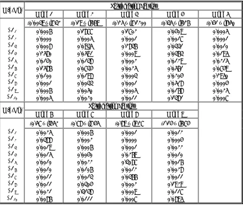
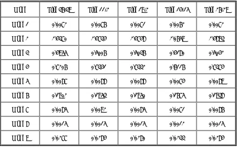
As the control objective is to provide additional damping to critical mode i.e. mode 1, only the controllability of this oscillatory mode has been considered. Initially, mode controllability analysis has been carried out considering a TCSC placed on line 8 -25, 14-34, 11-12, 12-13, 23-24, 36-39, 33-34, 16-31, 17-18, 36-37, 11-2, 19-2, 14-15, 26-29, 25-26, 28-29 and 26-28 respectively. Tables 3 and 4 show the residues for nine electro-mechanical modes. The mode controllability in Tables 3 and 4, shows that when a TCSC is installed in line 11-12, the controllability for mode 1 is better than other lines. So a TCSC is installed in line 11-12, which will improve damping mode 1.
5. CONVENTIONAL POWER SYSTEM STABILIZER (CPSS)
The typical structure of a conventional PSS is shown in Figure 3 [2]. To provide pure damping, the CPSS should have appropriate phase-lead
characteristics to compensate the phase-lag between the generator exciter input and electrical output torque. Two lead-lag blocks are used in this paper although the number and characteristics of phase compensation units could be modified according to the design requirements.
The gain and time constants of the phase compensation units therefore need to be determined such that the system should give good dynamic performances. In this case also, limits are imposed on the output of CPSS and as mentioned in Section 3 and positive and negative limits are considered as 0.2 pu and -0.1 pu respectively.
6. P-I-D POWER SYSTEM STABILIZER (P-I-D PSS)
Block diagram of the P-I-D power system stabilizer is shown in Figure 4. The input signal of the P-I-D stabilizer is the speed (∆ω) of which the integral is the torque angle (∆δ) and the derivative is acceleration (Δω =Δα). Therefore, the proposed P-I-D stabilizer may be called as Δω−Δδ−Δω stabilizer. In order to restrict the level of the generator terminal voltage fluctuation during transient conditions, limits are imposed on power system stabilizer output. To ensure maximum contribution of the stabilizer, use of relatively large positive limits, i.e., 0.1 pu to 0.2 pu and negative limits of –0.05 pu to –0.1 pu is reported [2]. In the present work, positive and negative limits are considered as 0.2 pu and –0.1 pu respectively.
7. TCSC CONTROLLERS
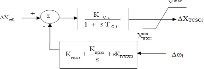
Figure 5 shows the structure of TCSC equipped with lead-lag controller and Figure 6 shows the structure of TCSC equipped with P-I-D controller. The outputs of the both controllers are multiplied with a gain and compared with ΔXref,i of the TCSC
and the error signal is an input to the TCSC. The speed deviation Δωi is used as an input to the both
controllers. This makes the proposed controllers easy for implementation. In these figures, ΔXref,i is
the reference angle and KCi and TCi are the gain
TABLE 3. Variation of Mode Controllability with TCSC Location.
Mode Line 8-25 Line 14-34 Line 11-12 Line 12-13 Line 23-24
Mode 1 0.0038 0.0059 0.0078 0.0075 0.0071
Mode 2 1.0865 0.6437 2.4766 2.3307 2.4694
Mode 3 0.2169 0.4406 0.5001 0.4743 0.5011
Mode 4 0.3263 0.1743 0.7344 0.6887 0.7314
Mode 5 0.0040 0.0077 0.0089 0.0083 0.0088
Mode 6 0.1433 0.0013 0.1921 0.1716 0.1932
Mode 7 0.0032 0.0071 0.0093 0.0092 0.0086
Mode 8 0.0007 0.0013 0.0015 0.0014 0.0015
Mode 9 0.0114 0.0243 0.0286 0.0268 0.0281
TABLE 4. Variation of Mode Controllability with TCSC Location.
Mode Line 36-39 Line 11-2 Line 19-2 Line 14-15 Line 26-29
Mode 1 0.0072 0.0076 0.0071 0.0062 0.0072
Mode 2 2.4370 2.4734 2.4748 2.0659 2.4893
Mode 3 0.4955 0.5006 0.5036 0.4180 0.5042
Mode 4 0.7206 0.7341 0.7332 0.6116 0.7374
Mode 5 0.0087 0.0088 0.0088 0.0074 0.0089
Mode 6 0.1902 0.1953 0.1950 0.1675 0.1938
Mode 7 0.0085 0.0092 0.0085 0.0071 0.0086
Mode 8 0.0015 0.0015 0.0015 0.0012 0.0015
Figure 3. The structure of a conventional power system stabilizer (CPSS).
Figure 4. The structure of a P-I-D power system stabilizer.
Figure 5. Structure of TCSC equipped with Lead-Lag controller.
In the both cases, TCSC is installed in line 11-12 as mentioned in Section 4 and input signal is taken from machine 10 for both controllers as machine 10 is nearer to this line.
8. DYNAMIC MODEL IN STATE SPACE FORM CONSIDERING CPSS P-I-D PSS AND
TCSC CONTROLLERS
The dynamic model in state space form considering CPSS is written as [28,29]:
p AX
X• = +Γ (5)
Where X and p are the state and disturbance vectors and A and Γ are real constant matrices of appropriate dimensions. In this case ∆PS1i, ∆PS2i
and Ui as shown in Figure 3, are considered as state
variables.
In this case, state vector X and disturbance vector p for the ith machine is defined as:
T '
i i i qi FDi Ri Ei S1i S2i i
X = Δδ Δω ΔE ΔE ΔV ΔV ΔP ΔP U (6)
and
[
]
Ti mi refi
p = ΔT ΔV (7)
The dynamic model in state space form considering P-I-D PSS is written as:
p AX
X• = +Γ (8)
Where X and p are the state and disturbance vectors and A and Γ are real constant matrices of appropriate dimensions.
In this case, state vector X and disturbance vector p for the ith machine is defined as:
T '
i i i qi FDi Ri Ei
X =
Δδ
Δω
Δ
E
Δ
E
Δ
V
Δ
V
(9)and
[
]
Ti mi refi
p = ΔT ΔV (10)
The dynamic model in state space form considering CPSS and TCSC equipped with lead-lag controller is written as:
p AX
X• = +Γ (11)
Where X and p are the state and disturbance vectors and A and Γ are real constant matrices of appropriate dimensions. In this case ∆PS1i, ∆PS2i,
Ui, for CPSS and ΔQS1iΔQS2iΔQS3i and ΔXTCSCi for
TCSC equipped with lead-lag controller as shown in Figure 5, are considered as state variables. In this case, state vector X and disturbance vector p for the ith machine is defined as:
Xi = [ΔδiΔωi ΔEqi' ΔEFDi ΔVRiΔVEi ΔPS1i ΔPS2i Ui
ΔQS1iΔQS2iΔQS3iΔXTCSCi]T(12)
and
[
]
Ti mi refi refi
p
=
Δ
T
Δ
V X
Δ
(13)
The dynamic model in state space form considering P-I-D PSS and TCSC equipped with P-I-D controller is written as:
p AX
X• = +Γ (14)
Where X and p are the state and disturbance vectors and A and Γ are real constant matrices of appropriate dimensions. In this case ΔXTCSCi
equipped with P-I-D controller as shown in Figure 6, is considered as state variable.
In this case, state vector X and disturbance vector p for the ith machine is defined as:
T '
i i i qi FDi Ri Ei TCSCi
X = Δδ Δω ΔE ΔE ΔV ΔV XΔ
(15) and
[
]
Ti mi refi refi
p
=
Δ
T
Δ
V X
Δ
(16)
9. OBJECTIVE FUNCTION
be the most meaningful and convenient measures of dynamic performances [30,31]. Penalizing only the speed excursions, an objective function based on the integral square error (ISE) criterion is considered in this study and is given by
dt 0 2 ) i ω Δ n 1 i ( J ∞
=
= (17)
Where, n is the number of machines. For ten machine thirty nine bus system, n = 10.
This objective function has a characteristic that it penalizes large errors heavily and low errors lightly. To compute the optimum parameter values a step disturbance of mechanical torque at machine 4 (i.e. ΔTm4=0.05 pu) was used to perturb the
system from its operating point.
10. GENETIC ALGORITHMS
Genetic algorithms (GAs), a way to randomly search for the best answer to tough problems were first suggested by John Holland in his book in Natural and Artificial systems [32]. Over the last few years, it is becoming important to solve a wide range of search, optimization and machine learning problems.
A GA (multi path search scheme) is an iterative procedure which maintains a constant size population p(t) of candidate solutions. The initial population p(0) can be chosen heuristically or at random [32]. The structures of the population p(t+1) (i.e., for next iteration called generation) are chosen from p(t) by randomize selection procedure that ensures that the expected number of times a structure chosen is approximately proportional to that structure’s performance relative to the rest of the population. In order to search other points in a search space, some variation is introduced into the new population by means of genetic operators (crossover and mutation).
Three processes, selection, mating and mutation are used to make the transition from one population generation to the next. These three steps are repeated to create new generation and it continues in this fashion until stopping condition is reached (such as maximum number of generations or resulting new population not improving enough).
10.1. Encoding
The design variables are mapped onto a fixed–length binary digit string which is constructed over the binary alphabet (0,1), and is concatenated head-to-tail to form one long string referred to as a chromosome. That is, every string contains all design variables.Each design variable is represented by a λ-bit string. We have to determine the value of λ. It is shown by Lin, et al [33] that
) ε min i x max i x ( 2 log i
λ ≥ − (18)
Where ximax = upper bound on xi, ximin = lower bound
on xi and ε = the resolution. For example if ε = 0.01,
ximax = 60, ximin = 20, then λi≥ 11.9658 but bit size
must be an integer and hence, in this case λi≥ 12.
10.2. Decoding
The physical value of i-th design variable xi is computed from the followingequations:
i
m a x m in
m in i i
i i i λ
(x x )
x x I
2 1
−
= +
− (19)
For example, if ε = 0.01; ximax = 60, ximin = 20.0
and λi = 12, then the bit string 100000000001 is
decoded to Ii =2049 and thus xi = 40.014652.
10.3. Fitness Function
In GAs, the value of fitness represents the “performance” which is used to rank the string and the ranking is then used to determine how to allocate reproductive opportunities. This means that individuals with higher fitness value will have higher probability of being selected as a parent. Actually the ‘fitness’ is defined as nonnegative figure of merit to be maximized which is directly associated with the objective function.In unconstrained maximization problem, the objective function can be adopted as the fitness function:
F = J(20)
Where F is the fitness function and J is the objective function.
according to the following equation:
J K F = (21)
Where K is a positive constant multiplier. To maximize the fitness function is same as minimize the objective function.
10.4. Control Parameters Selected
First of all, effects of population were observed. Different population sizes (40-80) were considered and it has been observed that the population size of 60 was satisfactory. After selecting the population size, the effect of mutation and crossover probabilities were examined. Different combination of mutation (Pm)probabilities (0.0001, 0.001, 0.005 and 0.01) and the crossover (Pc) probabilities (0.6, 0.8, 0.9 and 1.0)
were tested and it was found that Pc = 1.0 and Pm =
0.005 give the best performance for all the operating conditions. It is worth mentioning here that the bit size (gene length) of each variable is taken as 10 (i.e., λ=10).
11. OPTIMIZATION OF CONTROLLER PARAMETERS
11.1. Optimization of CPSS and P-I-D PSS
Parameters
The parameters of and CPSS and P-I-D PSS are optimized using GA. In the case of CPSS, gains and time constants i.e. KS4, T14, T24,T34 and T44 are optimized by minimizing the
objective function given by Equation 17. The washout time constant TW4 is considered as 10
Seconds. In the case of P-I-D PSS, gains i.e. KP4,
KI4 and KD4 are optimized by minimizing the
objective function given by Equation 17. Constraints are also imposed on these parameters. The maximum and minimum limiting values of these parameters are given in Appendix. Optimum gains and different time constants of CPSS and optimum gains of P-I-D PSS are presented in Tables 5 and 6 respectively.
11.2. Optimization of Lead-Lag Controller
Parameters
The CPSS parameters for machine 4 presented in Table 5 is kept fixed and the problem is now to optimize the parameters oflead-lag controller of TCSC. As the input signals for TCSC controllers have been taken from machine 10, the speed deviations of machine-10 (∆ω10) is
used as the input signal to the lead-lag controller of TCSC.
In the case of TCSC equipped with lead-lag controller, three parameters KSTCSC10, T1TCSC10,
T2TCSC10, T3TCSC10 and T4TCSC10 are optimized by
minimizing the objective function given by Equation 17 and TWTCSC10 is taken as 10 seconds.
Table 7 gives the optimum parameters of lead-lag controllers of TCSC.
11.3. Optimization of P-I-D Controller
Parameters
The P-I-D PSS parameters for machine 4 presented in Table 6 are kept fixed and the problem is now to optimize the parameters of P-I-D controller of TCSC. As the input signals for TCSC controllers have been taken from machine 10, the speed deviations of machine-10 (∆ω10) areused as the input signals to the P-I-D controller of TCSC.
In the case of TCSC equipped with P-I-D controller, three parameters KPTCSC10, KITCSC10, and
KDTCSC10 are optimized by minimizing the
objective function given by Equation 17. Table 8 gives the optimum parameters of P-I-D controllers of TCSC.
12. RESULTS AND DISCUSSIONS
TABLE 5. Optimum Values of the Gains and Parameters of CPSS for Machine 4.
Optimum Gains and Parameters of CPSS
KS4 = 0.1817 T14 = 0.4272 T24 = 0.0805 T34 = 0.5143 T44 = 0.0959
TABLE 6. Optimum Values of the Gains of P-I-D Controller for Machine 4.
Optimum Gains of P-I-D PSS
KP4 = 2.6598 KI4 = 0.0143. KD4 = 4.4889
TABLE 7. Optimum Values of the Gains and Parameters of TCSC Equipped with Lead-Lag Controller for Machine 10.
Optimum gains and parameters of TCSC Equipped with Lead-Lag Controller
KSTCSC10 = 2.7491 T1TCSC10 = 0.7049 T2TCSC10 = 0.0630 T4TCSC10 = 0.1198
TABLE 8. Optimum Values of the Gains of P-I-D Controller for Machine 10.
Optimum Gains TCSC Equipped with P-I-D Controller
KPTCSC10 = 5.8806 KITCSC10 = 0.0246 KDTCSC10 = 6.8347
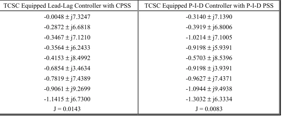
TABLE 9. Comparison of the Electromechanical Mode Eigenvalues and Minimum Value of J Considering TCSC Equipped Lead-Lag Controller with CPSS and TCSC Equipped P-I-D Controller with P-I-D PSS.
TCSC Equipped Lead-Lag Controller with CPSS TCSC Equipped P-I-D Controller with P-I-D PSS -0.0048 ± j7.3247
-0.2872 ± j6.6818 -0.3467 ± j7.1210 -0.3564 ± j6.2433 -0.4153 ± j8.4992 -0.6854 ± j3.4634 -0.7819 ± j7.4389 -0.9061 ± j9.2699 -1.1415 ± j6.7300
J = 0.0143
-0.3140 ± j7.1390 -0.3919 ± j6.8006 -1.0214 ± j7.1005 -0.9198 ± j5.9391 -0.5703 ± j8.5396 -0.9198 ± j3.9391 -0.9627 ± j7.4371 -1.0944 ± j9.4938 -1.3032 ± j6.3334
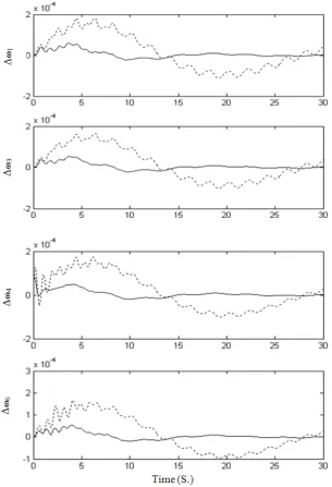
to that of TCSC equipped with lead-lag controller and CPSS. From Table 9, it is clearly seen that TCSC equipped with P-I-D controller and P-I-D PSS is much better than that of TCSC equipped with lead-lag controller and CPSS. This is further compared by plotting the dynamic responses. Figure 7 shows the speed deviation of some of
the machines considering lead-lag controllers in machine 10 and CPSS in machine 4 and P-I-D controllers in machine 10 and P-I-D PSS in machine 4. It was found that settling time for these responses considering TCSC equipped with lead-lag controller and CPSS is more than 25 seconds. Whereas settling time for these responses Figure 7. Dynamic responses for ten machine thirty nine bus system considering optimum parameters settings of
TCSC equipped with P-I-D controller and P-I-D PSS and TCSC equipped with lead-lag controller and CPSS. (----TCSC equipped with P-I-D controller and P-I-D PSS,
considering TCSC equipped with P-I-D controller and P-I-D PSS is about 12 seconds and peak deviations are also very much less. Therefore, it may be concluded that TCSC equipped with P-I-D Controller and P-I-D PSS gives superior dynamic performances than that of TCSC equipped with lead-lag controller and CPSS.
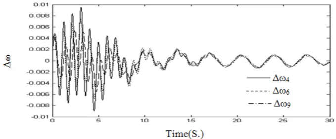
For further illustration, a 6 cycle, 3-phase to ground fault at bus 14 on the line between buses 14 and 34 was simulated. Figure 8 shows the system response to a 3-phase to ground fault at bus 14. It is seen that TCSC equipped with P-I-D controller and P-I-D PSS do not adversely affect the transient stability and damp out the oscillations following the fault clearing.
13. CONCLUSIONS
In the present work, proportional-integral-derivative controller (P-I-D Controller) for TCSC and P-I-D PSS has been proposed for the enhancement of the dynamic stability of multi-machine power system. Gain settings of D controller of TCSC and P-I-D PSS and also the gains and time constants of conventional phase lead-lag controller of TCSC and CPSS have been optimized using genetic algorithm (GA). Analysis reveals that the TCSC equipped with P-I-D controller and P-I-D PSS give much better dynamic performances in terms of peak deviation and settling time as compared to that of TCSC equipped with phase lead-lag controller and CPSS. It was also found that the
P-I-D controller for TCSC and P-I-P-I-D PSS do not adversely affect the transient stability and damp out oscillations following the fault clearing.
14. APPENDIX
The limiting values of gains and parameters of CPSS for multimachine system are given below:
KSmin = 0.01, KSmax = 10.0, T1min = 0.1, T1max = 2.0,
T2min = 0.01, T2max = 0.5, T3min = 0.1, T3max = 2.0,
T4min = 0.01, T4max = 0.5.
The limiting values of gains of P-I-D PSS for multimachine system are given below:
KPmin = -15, KPmax = 15, KImin = -0.1, KImax = 0.1,
KDmin = -10, KDmax = 10.
The limiting values of gains and parameters of TCSC Equipped with Lead-Lag Controller for multimachine system are given below:
KSTCSCmin = 0.01, KSTCSCmax = 10.0, T1TCSCmin = 0.1,
T1TCSCmax = 2.0, T2TCSCmin = 0.01, T2TCSCmax = 0.5,
T3TCSCmin = 0.1, T3TCSCmax = 2.0, T4TCSCmin = 0.01,
T4TCSCmax = 0.5.
The limiting values of gains of TCSC Equipped with P-I-D Controller multimachine system are given below:
KPTCSCmin = -15, KPTCSCmax = 15, KITCSCmin = -0.1,
KITCSCmax = 0.1, KDTCSCmin = -10, KDTCSCmax = 10.
15. REFERENCES
1. DeMello, F.P. and Concordia, C., “Concepts of Synchronous Machine Stability as Affected by Excitation Control”, IEEE Transactions on Power Apparatus and
Systems, Vol. PAS-88, (April 1969), 316-329.
2. Kundur, P., Klein, M., Rogers, G.J. and Zywno, M.S., “Application of Power System Stabilizers for Enhancement of Overall System Stability”, IEEE
Transactions on Power Apparatus and Systems, Vol. 4,
No. 2, (May1989), 614-626.
3. Fleming, R.J., Mohan, M.A. and Parvatisam, K., “Selection of Parameters of Stabilizers in Multimachine Power Systems”, IEEE Transactions on Power Apparatus
and Systems, Vol. PAS-100, No. 5, (May 1981),
2329-2333.
4. Abido, M.A., “Parameter Optimization of Multimachine Power System Stabilizers using Genetic Local Search”,
Electrical Power and Energy Systems, Vol. 23, (2001),
785-794.
5. Abdel-Magid, Y.L., Abido, M.A. and Mantawy, A.H., “Robust Tuning of Power System Stabilizers in Multimachine Power Systems”, IEEE Transactions on
Power Systems, Vol. 15, No. 2, (May 2000), 735-740.
6. Zhang, P. and Coonick, A.H., “Coordinated Synthesis of PSS Parameters in Multi-Machine Power Systems using the Method of Inequalities Applied to Genetic Algorithms”, IEEE Transactions on Power Systems, Vol. 15, No.2, (May 2000), 811-816.
7. Lei, X., Huang, H., Zheng, S.L., Jiang, D.Z. and Sun, Z.W. “Global Tuning of Power System Stabilizers in Multi-Machine Systems”, Electrical Power System
Research, Vol. 58, (2001), 103-110.
8. Chen, X.R., Pahalawaththa, N.C., Annakkage, U.D. and Kumble, C.S., “Controlled Series Compensation for Improving the Stability of Multi-Machine Power Systems”, IEE Proceedings Generation Transmission
Distribution, Vol. 142, No. 4, (July 1995), 361-366.
9. Paserba, J.J., Miller, N.W., Larsen, E.V. and Piwko, R.J., “A Thyristor Controlled Series Compensation Model for Power System Stability Analysis”, IEEE
Transactions on Power Delivery, Vol. 10, No. 3, (July
1995), 1471-1478.
10. Jalali, S.G., Hedin, R.A., Pereira, M. and Sadek, K., “A stability Model for the Advanced Series Compensator”,
IEEE Transactions on Power Delivery, Vol. 11, No. 2,
(April 1996), 1128-1137.
11. Chang, J. and Chow, J.H., “Time-optimal Series Capacitor Control for Damping Interarea Modes in Interconnected Power Systems”, IEEE Transactions on Power Systems, Vol. 12, No. 1, (February 1997), 215-221.
12. Rouco,L.and Pagola,F.L.,“AnEigensensitivityApproach to Location and Controller Design of Controllable Series Capacitors for Damping Power System Oscillations”,
IEEE Transactions on Power Systems, Vol. 12, No. 4,
(November 1997), 1660-1666.
13. Yang, N., Liu, Q. and McCalley, J.D., “TCSC Controller Design for Damping Interarea Oscillations”
IEEE Transactions on Power Delivery, Vol. 13, No. 4,
(November 1998), 1304-1310.
14. Tso, S.K., Liang, J. and Zhou, X.X., “Coordination of
TCSC and SVC for Improvement of Power System Performance with NN-Based Parameter Adaptation”,
Electric Power and Energy Systems, Vol. 21, (1999),
235-244.
15. Li, B.H., Wu, Q.H., Turner, D.R., Wang, P.Y. and Zhou, X.X., “Modeling of TCSC Dynamics for Control and Analysis of Power System Stability”, Electric
Power and Energy Systems, Vol. 22, (2000), 43-49.
16. Son, K.M. and Park, J.K. “On the Robust LQG Control of TCSC for Damping Power System Oscillations”,
IEEE Transactions on Power Systems, Vol. 15, No. 4,
(November 2000), 1306-1312.
17. Fan, L., Feliachi, A. and Schoder, K., “Selection and Design of a TCSC Control Signal in Damping Power System Inter-Area Oscillations for Multiple Operating Conditions”, Electric Power System Research, Vol. 62, (2002), 127-137.
18. Ishimaru, M., Yokoyama, R., Shirai, G. and Niimura, T., “Robust Thyristor-Controlled Series Capacitor Controller Design Based on Linear Matrix Inequality for a Multi-Machine Power System”, Electric Power and Energy
Systems, Vol. 24, (2002), 621-629.
19. Del Rosso, A.D., Canizares, C.A. and Dona, V.M., “A Study of TCSC Controller Design for Power System Stability Improvement”, IEEE Transactions on Power
Systems, Vol. 18, No. 4, (November 2003), 1487-1496.
20. Chen,J.,Lie,T.T.andVilathgamuwa,D.M., “Enhancement of Power System Damping using VSC-Based Series Connected FACTS Controllers”, IEEE Proc. Gener.
Transm. Disrtib., Vol. 150, No. 3, (May 2003), 353–359.
21. Wang, H.F., “Design of Non-Negatively Interactive FACTS-Based Stabilizers in Multi-Machine Power Systems”, Electric Power System Research, Vol. 50, (1999), 169-174.
22. Elenius, S., Uhlen, K. and Lakervi, E., “Effects of Controlled Shunt and Series Compensation on Damping in the Nordel System”, IEEE Transactions on Power
Apparatus and Systems, Vol. 20, No. 4, (November
2005), 1946-1957.
23. Liu, Q., Vittal, V. and Elia, N. “LPV Supplementary Damping Controller Design for a Thyristor Controlled Series Capacitor (TCSC) Device”, IEEE Transactions
on Power Apparatus and Systems, Vol. 21, No. 3, (July
2006), 1242-1249.
24. Simoes, A.M., Savelli, D.C., Pellanda, P.C., Martins, N. and Apkarian, P., “Robust Design of a TCSC Oscillation Damping Controller in a Weak 500-kV Interconnection Considering Multiple Power Flow Scenarios and External Disturbances”, IEEE Transactions on Power
Apparatus and Systems, Vol. 24, No. 1, (February 2009),
226-236.
25. Chaturvedi, D.K., Malik, O.P. and Kalra, P.K., “Studies with a Generalized Neuron Based PSS on a Multi-Machine Power System”, IJE Transactions B:
Applications, Vol. 17, No. 2, (July 2004), 131-140.
26. Hiyama, T. and Sameshima, T., “Fuzzy Logic Control Scheme for on-Line Stabilization of Multimachine Power System”, Fuzzy Sets and Systems, Vol. 39, (1991), 181-194.
Power Systems, Part I and II”, IEEE Transactions on
Power Apparatus and Systems, Vol. PAS-101, No. 9,
(September 1982), 3117-3134.
28. Anderson, P.M. and Fouad, A.A., “Power System Control and Stability”, The Iowa State University Press, A Book, Iowa, U.S.A., (1977).
29. Yu, Y.-N., “Electric Power System Dynamics”, A Book, Academic Press, New York, U.S.A., (1983). 30. Schultz, W.C. and Rideout, V.C., “Control System
Performance Measures: Past, Present and Future”, IRE
Transactions on Automatic Control, Vol. 22, (1961),
22-35.
31. Ogata, K., “Modern Control Engineering”, A book, Prentice-Hall, Englewood Cliffs, NJ, U.S.A., (1970), 293-313.
32. Holland, J.H., “Adaptation in Nature and Artificial Systems”, University of Michigan Pres, Am Arrbor,
MI, U.S.A., (1975).