Please cite this article as: M. Tajik Jamal-Abad, S. Saedodin, M. Aminy,Analytical Investigation of Forced Convection in Thermally Developed Region of a Channel Partially Filled with an Asymmetric Porous Material- LTNE Model , International Journal of Engineering (IJE), TRANSACTIONS A: Basics Vol. 29, No. 7, (July 2016)
International Journal of Engineering
J o u r n a l H o m e p a g e : w w w . i j e . i rAnalytical Investigation of Forced Convection in Thermally Developed Region of a
Channel Partially Filled with an Asymmetric Porous Material- LTNE Model
M. Tajik Jamal-Abad*a, S. Saedodina, M. Aminyb
a Mechanical engineering department, Semnan University, Semnan, Iran
b Department of Renewable Energy, Materials and Energy Research Center, Karaj, Iran
P A P E R I N F O
Paper history: Received 27 March 2016
Received in revised form 26 May 2016 Accepted 02 June 2016
Keywords:
Channels Partially Filled with Porous Material
Analytical Solution
An Asymmetric Porous Medium Heat Transfer Enhancement LTNE Model
A B S T R A C T
In the present work forced convection flow in a channel partly filled with a porous media under asymmetric heat flux, boundary condition has been investigated. The porous material is distributed on the bottom wall of the channel. Darcy–Brinkman and LTNE model have been assumed in order to solve momentum and energy equations, respectively. Fully developed conditions are considered in order to solve velocity and the temperature fields. Due to the different configuration of porous media, new velocity profiles are introduced. The Nusselt number (Nu) is deduced in terms of the porous thickness(S), thermal conductivity ratio (k) and Darcy number (Da). The results illustrate that the fluid temperature in the clear region declines when the porous thickness grows at constant k. The temperature difference between the fluid phase and the solid phase decreases, as Bi increases. There are two stages for variation of Nu number with S and the optimum Nusselt thicknesses of the porous medium Sopt,Nu is found for different value of k and Bi. Moreover, at the particular value of S Nu number is independent of Bi and k for each Da number.
doi: 10.5829/idosi.ije.2016.29.07a.00
1. INTRODUCTION1
Heat transfer in porous media plays a crucial role in many industrial devices such as heat exchangers in petroleum engineering, filtration, geomechanics, and storage of absorbed solar energy [1-5]. The fluid flow and heat transfer in porous channels have been extensively investigated because of the wide range of potential engineering applications [6-8]. Uddin et al. [9] investigated numerically the two-dimensional free convective flows along an isothermal horizontal flat plate located in a porous media. Noghrehabadi et al. [10] investigated the natural convection of nanofluid over a vertical cone in a porous medium. Poulikakos and Kazmierczak [11] studied forced convection in a channel whose walls are layered by a porous medium. Forced-convection cooling in channels with filled porous media was investigated by Rizk and Kleinstreuer
1*Corresponding Author’s Email:miladtajik6@gmail.com(M. Tajik
Jamal-Abad)
receiver with porous media is investigated numerically by Wang et al. [18]. The effect of radiation on heat transfer over a permeable flat plate in a porous medium was investigated by Mabood and Khan [19].
Channels partially filled with porous materials can be used in many industries such as solar absorbers, fuel cells, and compact heat exchangers. Using porous media causes considerable pressure drops in a system. Hence, the partial filling is a noteworthy way in order to elude this negative effect. Alkam et al. [20] compared the effect of using the porous material on one wall and on both walls of the channel. the constant wall temperature condition is assumed as a boundary condition. They showed that for the low porous fraction the increase in heat transfer is higher when the two walls are covered equally with the porous material. Forced flow in a parallel channel partially filled with a porous medium with respect to the Darcy–Brinkman–Forchheimer model was studied numerically by Jang and Chen [21]. Satyamurty and Bhargavi [22] studied heat transfer in a thermally developing region of a channel and porous material is deposited on one wall partially. The validity of LTE in a partially filled porous material in a channel has been studied analytically by Yang and Vafai [23]. There are two methods for modeling the energy equation in a porous media, local thermal equilibrium (LTE) and local thermal non-equilibrium (LTNE) models. The LTE assume that solid and fluid temperature is equal and there is no difference between them. However, this assumption is not precise because this temperature difference may be large in some cases. Hence, using LTNE model seems to be more accurate. Heat transfer in a channel partially filled with a porous medium under the constant heat flux was studied by Mahmoudi and Maerefat [24]. The local thermal non-equilibrium model and thermally developed condition were deemed in order to acquire the exact solutions of temperature fields inside the porous region and in the clear region. Mahmoudi et al. [25] analytically studied forced convection in a channel partially filled with a porous medium in thermally and hydrodynamically developing the region. They introduced an exact solution for the solid and fluid temperature in both regions.
In this study forced convection flow in a channel partly filled with a porous media under asymmetric heat flux boundary condition has been investigated. Porous substrate has been inserted asymmetric in the channel and attached to the lower plate.
2. GOVERING EQUATIONS
The schematic diagram of the problem is shown in Figure 1. A porous foam is deposited on the inner wall of the lower plate. At the entrance of the duct, the fluid velocity is kept at a value of unite and the fluid
temperature is kept at Tin. The following assumptions are used in the analysis:
Incompressible flow in the porous media is assumed.
The steady-state fully developed forced convection is desired.
The effect of natural convection and the radiation on heat transfer are neglected.
It is assumed that there is different between the temperature of the solid and fluid phases (LNTE condition).
The porosity of the medium is assumed to be uniform and constant.
2. 1. Momentum Equations For analytical
investigation two momentum equations are introduced. Momentum equation in the clear region (hp<y<h0)
2 2 0
f
u p
x y
(1)
Previous research illustrated that for Da<10-3 the assumption of plug flow is valid in the porous medium and the inertia term in the momentum equation is insignificant [26]. Therefore, the Darcy-Brinkman model can be declared for the momentum equation. Momentum equation in the porous medium (0<y<hp)
2
0 2
u
p p
u
eff p
x y K
(2)
where u is the fluid velocity, K is the permeability,
is viscosity and subscript of eff introduces effective property.2. 2. Energy Equations Energy equation for the fluid in the clear region (hp<y<h0)
2
1 1
2
f f
p f f
T T
C u k
x y
(3)
The steady state energy balance equations of the solid and fluid phases in the porous media region (0<y<hp) are [27]:
2
2 2
, 2 2
f f
p p f eff sf sf s f
T T
C u k h a T T
x y
(4)
2
, 2 2
0 ks eff Ts h asf sf Ts Tf y
(5)
Equations (4) and (5) are the energy equations for the fluid and solid phases, respectively. In these equations the subscripts ‘s’ and ‘f’ denote the solid and fluid phases, respectively. T is temperature, cp is the specific heat of the fluid phase at constant pressure, the subscripts f1and f2represent the fluid phase in the clear region and the porous medium, respectively. ks,eff and kf,eff are effective thermal conductivities of the solid and fluid phases given by:
seff
s k
k, 1
(6)f eff ,
f k
k
(7)Specific surface area and the fluid-to-solid heat transfer coefficient appearing in the energy equations are expressed as [27]:
p
sf d
a 61 (8)
0.6 1
3 2 1.1Pr
f p
sf p
k ud
h d
(9)
dp is the particle diameter and Pr is the Prandtl number
2. 3. Boundary Condition The boundary
conditions for the momentum equations are represented by:
0 0
uf at yh (10)
, uf up
uf up nf eff at y hp
y y
(11)
0 0
u p
at y y
(12)
where eff and is the porosity of the medium. The boundary conditions for the energy equations are represented by:
2
0, 0
f s
T T
at y
y y
(13)
1
0 ,
f
f w
T
k q at y h
y
(14)
1 2,
f f p
T T at yh (15)
There are two models to explain the constant heat flux boundary at the porous-fluid interfac [28].
The first approach is to deem that heat is divided into the two phases on the basis of their effective conductivities and their corresponding temperature gradients [24]. The second model is to assume that an
equal amount of heat flux will be obtained by each of the individual phases at the interface [28]. By using the first approach, a good agreement between numerical and experimental results have been found by Hwang et al. [6] and Marafai and Vafai [8] have been found analytical solutions for the temperature profiles and the Nusselt number. In this research the first approach has been used to describe the boundary condition at the inter-face of the porous medium and the clear region. Therefore:
2 int ,
f s erface p
T T T at yh (16)
2 1
, , int ,
f f
s
s eff f eff f erface p
T T
T
k k k q at y h
y y y
(17)
where
1 int
p f
erface f
y h
T
q k
y
qinterfaceis the amount of heat flux transferred from the clear flow to the porous medium.
2. 4. Normalization The governing equations are
normalized and the following dimensionless variables are introduced:
, int
0
, , p, s eff erface
o r o w
k T T
h
y u
Y U S
h u h q h
(18a)
The average velocity at the channel cross-section area is depicted as:
1 0
p o
p
h h
u u dyp u dyf
h ho
(19)The non-dimensional momentum and energy equations and their associated boundary conditions are:
Momentum equation in the clear region (S<Y<1)
2 0 1
2 U f Y
(20)
Momentum equation in the porous medium (0<Y<S)
2 0 1
2 Up Up
Da Y
(21)
where Da is Darcy numberDaK ho2and ur is a characteristic velocity defined as:
2
ho p
ur
x
and Uu ur
The associated boundary conditions are:
0 1
, Up Uf
Uf Up at Y S
Y Y
(23)
0 0
U p
at Y Y
(24)
Energy equation in the clear region (S<Y<1)
1( ) f
f U
k Y
U
(25)
Fluid phase energy equation in the porous medium (0<Y<S)
2 2
1
( ) ( ) ( )
p
f s f
U
Y Bi y y
U k (26)
Solid phase energy equation in the porous medium (0<Y<S)
2
0 s( )Y Bi s( )y f ( )y (27)
The associated boundary conditions are:
1 1
f k at Y
(28)
1 0
f at Y S
(29)
2 0
f s at Y S
(30)
2 , 1 0
f k s at Y
(31)
where k is the ratio of the effective thermal conductivity of the solid to that of the fluid and Bi is the Biot number
2
0 ,
, ,
,
sf sf s eff
s eff f eff
a h h k
Bi k
k k
2. 5. Velocity Distribution Solving ordinary differential Equations (20) and (21) and applying associated boundary conditions, hydrodynamics of the present problem can be obtained. Velocity distributions of the fluid in the clear region.
1 2 2
Uf Y AYB (32)
2 ( cosh( )( 0.5 (1 ) )
sinh( ) ( 1)cosh( )
Z Da ZS Da S
A S
ZS Z S ZS
(33)
1 2
B A (34)
Within the porous region:
sinh( ) cosh( )
UpC ZY D ZY Da (35)
2
(cosh( ) 1) 0.5( 1) ( 1) sinh( )
Da ZS S A S
C
ZS
(36)
D Da (37)
where Z ( 1 0.5)
Da
and S is the ratio of porous
thickness to the channel height.
By using this integral the average velocity is:
3 2
sinh( ) (cosh( ) 1)
2 2
1
(1 ) (1 ) (1 )
6 2
D C
U SDa ZS ZS
A
S S B S
(38)
The amount of heat flux at the interface of the porous medium and the clear flow is obtained as:
3 2
cosh( ) 1 sinh( ) 1
1
sinh( ) (cosh( ) 1) (1 ) (1 ) (1 )
2 2 6 2
C D
ZS ZS DaS
Z Z
D C A
SDa ZS ZS S S B S
(39)
The pressure drop can be calculated by defining the friction factor [26]:
2 0.5
h
D p
f
x u
(40)
where Dh is the hydraulic diameter and f is the friction factor. It is worthwhile to mention that the pressure gradient in the fully developed region is constant. The friction factor which is derived from the characteristic velocity (ur) is:
8 Re
f U
(41)
where Re is a Reynolds number.
2. 5. Temperature Distribution (Local Thermal Equilibrium)
2. 5. 1. Clear Region The temperature distribution of the flow in the clear region can be calculated by Integrating the ordinary differential Equation (29)
4 3 2
1( ) 1 2
24 6 2
f
k Y Y Y
Y A B C Y C
U
(42)
1 1 6 2
A
C B U (43)
4 3 2
2
1
24 6 2 6 2
S S S A
C A B S B U
(44)
In the above equations A and B are constant parameters which are defined by Equations (33) and (34).
temperature of the solid and fluid phases (Ts Tf). Both
energy equations have two unknown functions and by two times derivative of Equations (26) and (27) with respect to Y, both of them involving one unknown function.
(4)
2
2( ) (1 ) f ( ) p( ) p( ) f
k
Y Bi k Y BiU Y U Y
U
(45)
(4)( ) (1 ) ( ) ( )
s s p
k
Y Bi k Y BiU Y
U
(46)
These equations can be solved by applying four boundary conditions. New boundary conditions should be derived in order to solve Equations (45) and (46). Therefore, by applying Equations (26) and (27) at Y=S and using boundary condition (30) result in
2
( )
( ) p
f
U S
S k
U
(47)
( ) 0
s S
(48)
Moreover, by derivative of Equations (26) and (27) and applying them at Y=0 and and using boundary condition (35) are expected as follow:
2
(0)
(0) p 1 1
f
U
k kBi k
U
(49)
(0) 1 1
s Bi k
(50)
With respect to the appropriate boundary conditions (Equations (47-50)), two ordinary differential equations (Equations (45-46)) can be easily solved and the temperature distribution for the fluid and solid phases within the porous region are reaped
3 2 22 2 2
2 2 2 2 1 1 2 2 S Y S s
C Z e
Uz Us Z e
Bi k
Z Z
U
Da Y S C
Y S Z (51)
32 2 2
2 2 2 2
2 2 2 2 2 1 1 ( ) 2 2 S Y S f p
C Z e
Z Bi Uz Us Z Bi e
k
Z Z
U
Da Bi Y S C Bi
U S Y S
Z (52) where
sinh( ) cosh( )
UzC ZY D ZY (53)
sinh( ) cosh( )
UsC ZS D ZS (54)
( ) sinh( ) cosh( )
p
U S C ZS D ZS Da (55)
2
cosh(Y) cosh(S) 1
(56)
1
Bi k
(57)
In the above equations C and D are constant parameters which are defined by Equations (40) and (41).
2. 6. Nusselt Number The Nusselt number at the
channel wall is defined:
w h
1f w m
q D
Nu for S
k T T
(58)
, 1 w hf eff w m
q D
Nu for S
k T T
(59)
where Dh is the hydraulic diameter of the channel and equal to 2h0. By using normalized parameters the Nusselt number can be written:
w2 m
1k
Nu for S
(60)
w2 m
1k
Nu for S
(61)
where w and m are the non-dimensional temperature for fluid at the channel wall and the non-dimensional mean temperature, respectively. They are defined as follows:
1 1 1 2
1
24 6 2
w f Y
k A B
C C U
(62)
1 1 1 1 0 0 1 0 S S
p LTE f f p LTE f f
S S
m S
p f
S
u dY u dY u dY u dY
U
u dY u dY
(63)Through some algebraic manipulations, it can be shown that:
3
2 2 2
3 4 1 1 2
2 2 2
2
1 5 1 6 7
2 ( ) 2
S
m
p
C Z
Z Bi Us Z Bi e
k Z Z
U
Da Bi C Bi
U S Z (64) where
2 2 2
1 2 2 2
2
1
tanh 1
cosh( )
tanh( )
Z S Us C Z
2 2
2 2 2 2
3 1
S S
S
C Z Us CZ D Ze CZ e
Z Z
Da
S e
(66)
2 2 2 2 2
3
( ) sinh(2 ) 4 sinh ( ) 2 ( )
4
4 ( )
4
C D ZS DC ZS ZS D C
Z
Da C
Z
(67)
4 C cosh(ZS) 1 Dsinh(ZS) DaS
Z Z
(68)
3
5 3 2
2 3
C S CZS DaS
Us
Z Z
(69)
2
6 2 2
D CZS Us DaS
Z
(70)
7 6
5 7
2
4 3
1 1 2
2
1 2
1 1 7
1
336 48 30 120
1 1
6 8 6 3 6
1
2 2
S A S A B
S
C AC C
AB B
S S
BC AC
S
(71)
Where
cosh( ) sinh( )
C ZS D ZS
(72)
3. RESULT AND DISCUSSIONS
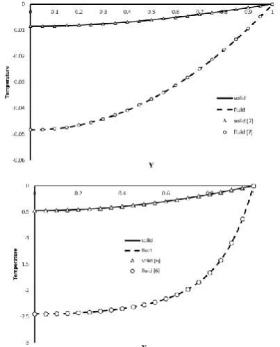
3. 1. Validation The present analytical velocity distribution for S=1and S=0 is compared with Previous research [8] and is shown in Figure 2. It can be seen that for both Darcy number, Da=10-3 and Da=10-5 there is an excellent agreement between the present result and Ref. [8]. Figure 3 depicts analytical temperature distribution for S=1 and Bi=0.5 at two different Da number and k value. It is clear that there is acceptable agreement between the present result and Marafie [8]. This means that, results can be relied for other porous substrate thickness value. Furthermore Table 1 is shown that there is an excellent agreement between the computed fully developed Nusselt number and analytical solution of Nusselt number for small Da (Da=10-8) [24]. It is worthwhile to mention that the Nusselt number of channel is twice the Nusselt number for a channel with an insulation side.
3. 2. Velocity Distribution In this study, the results are presented for a broad range of Da number and a constant porosity ( 0.9).The effect of porous
substrate thickness (S) on the axial velocity for Da=10-3 and Da=10-5 is illustrated in Figure 4 The most outstanding feature of figure is that the axial velocity in the clear region near the wall and porous-fluid interface increases by growing the porous layer thickness.
Figure 2. the axial velocity profile of the present study for S=1 and S=0, (a) Da=10-3, (b) Da=10-5
TABLE 1. The Nu number of present study and Ref. [24] and Ref. [8] for S=1, Da=10-8.
k Bi Nu(Ref. [8]) Nu(Ref. [24]) 2Nu(present study)
100 0.01 16.759 16.756 16.76 100 1 329.819 329.753 329.89
0.01 0.01 12.000 11.998 12
0.01 1 12.034 12.032 12.037
Figure 4. Effect of porous substrate thickness on the axial velocity profile, (a) Da=10-3 and (b) Da=10-5
In fact, because of hydraulic resistance of the porous region against the flow, most of the fluid passes through the clear region. The location of the maximum velocity shifts towards the wall by growing S. However, the gap between porous medial and channel wall in a certain porous medium thickness becomes too small and fluid is forced to flow through the porous region, so the maximum velocity decrease. A comparison between two figures brings out that the axial velocity in the porous substrate increases when Da number increases in spite of the fact that the maximum velocity in the clear region increases by decreasing Da number. This is due to the fact that at lower Da numbers the porous region becomes dense and the fluid is forced to escape to the clear region.
3. 3. Temperature Distributions The dimensionless temperature distributions for different values of Bi and k at S=0.9 are shown in Figure 5 for high Darcy number (Da=10-3). The outstanding feature of graphs is that, for constant value of k, the temperature
difference between the fluid phase and the solid phase is larger for low Bi number. In fact as Bi increases, the internal heat exchange between two phases increases, hence the temperature difference declines (Figure 5(a)). Moreover, at low value of k, although the solid temperature distribution changes significantly by increasing Bi, the fluid temperature distribution remains constant approximately (Figure 5(b) and Figure 5(a)). The contrast pattern can be seen at high value of k, as Bi reduces the fluid temperature distribution decreases considerably. However, there is no change is observed for the solid temperature distribution (Figure 5(c) and Figure 5(d)). The reason is that at high value of Da number the permeability of porous substrate is great and under this condition when the value of k is high the fluid conductivity is negligible, hence the transverse diffusion of the clear fluid to the porous medium is more significant and the temperature difference between the fluid phases is high. On the other hand, for low value of k the fluid conductivity is great and it is overcoming mechanism of heat transfer.
Da number, for high value of Da number the Nusselt number monotonically augments with porous medium thickness.
The optimum Nusselt thicknesses of the porous medium are 0.90, 0.95, 1 and 1 at Da numbers of 10-6, 10-5, 10-4 and 10-3, respectively.
(a)k=0.1, Bi=0.1 (b)k=0.1, Bi=10
(c)k=10, Bi=0.1 (d)k=10, Bi=10
Figure 5.Temperature distributions for fluid and solid phases for high Darcy number and S=0.9
(a)k=0.1, Bi=0.1 (b)k=0.1, Bi=10
(c)k=10, Bi=0.1 (d)k=10, Bi=10
4. CONCLUSION
In this paper the forced convection flow in a channel partially filled with a porous material has been investigated analytically. The lower wall of the channel is insulated and constant heat flux is imposed on another wall. Overally using porous media causes to improve the heat transfer and this fact has been proofed by privious researchs [31-32]. Other major results of the present study are highlighted as following:
Exact solutions were derived for temperature distribution and Nusselt number as function of the porous material thickness (S), thermal conductivity ratio (k) and Darcy number (Da)
In a constant value of k, the fluid temperature in the clear region declines when the maximum velocity increases result in the enhancement of the porous thickness and the temperature difference between two phases decreases when Bi increases.
Two stages are observed for the variation of Nu number versus S almost at all value of k and Bi. In the first stage Nusselt number increases with S and it reaches to the maximum. In the second stage, as S further increases, the Nu number decreases.
5. REFERENCES
1. Jamal-Abad, M.T. and Zamzamian, A., "Thermal conductivity of cu and al-water nanofluids", International Journal of Engineering Transactions B: Application, Vol. 26, No. 8, (2013), 821-828.
2. Zamzamian, A. and Jamal-Abadi, M.T., "Factor effect estimation in the convective heat transfer coefficient enhancement of al2o3/eg nanofluid in a double-pipe heat exchanger", International Journal of Engineering-Transactions B: Applications, Vol. 26, No. 8, (2013), 837-844. 3. Baniamerian, Z., Mehdipour, R. and Kargar, F., "A numerical
investigation on aerodynamic coefficients of solar troughs considering terrain effects and vortex shedding.", International Journal of Engineering Transactions C: Aspects, Vol. 28, No. 6 (2015), 940-948.
4. Kasaeian, A., Mobarakeh, M.D., Golzari, S. and Akhlaghi, M., "Energy and exergy analysis of air pv/t collector of forced convection with and without glass cover", International Journal of Engineering-Transactions B: Applications, Vol. 26, No. 8, (2013), 913-926.
5. Owrak, M., Aminy, M., Jamal-Abad, M.T. and Dehghan, M., "Experiments and simulations on the thermal performance of a sunspace attached to a room including heat-storing porous bed and water tanks", Building and Environment, Vol. 92, No., (2015), 142-151.
6. Hwang, G., Wu, C. and Chao, C., "Investigation of non-darcian forced convection in an asymmetrically heated sintered porous channel", Journal of Heat Transfer, Vol. 117, No. 3, (1995), 725-732.
7. Jamal-Abad, M.T., Saedodin, S. and Aminy, M., "Heat transfer in concentrated solar air-heaters filled with a porous medium with radiation effects: A perturbation solution", Renewable Energy, Vol. 91, (2016), 147-154.
8. Marafie, A. and Vafai, K., "Analysis of non-darcian effects on temperature differentials in porous media", International Journal of Heat and Mass Transfer, Vol. 44, No. 23, (2001), 4401-4411.
9. Jashim Uddin, M., Khan, W. and Ismail, A., "Free convective flow of non-newtonian nanofluids in porous media with gyrotactic microorganism", Journal of Thermophysics and Heat Transfer, Vol. 27, No. 2, (2013), 326-333.
10. Noghrehabadi, A., Behseresht, A., Ghalambaz, M. and Behseresht, J., "Natural-convection flow of nanofluids over vertical cone embedded in non-darcy porous media", Journal of Thermophysics and Heat Transfer, Vol. 27, No. 2, (2013), 334-341.
11. Poulikakos, D. and Kazmierczak, M., "Forced convection in a duct partially filled with a porous material", Journal of Heat Transfer, Vol. 109, No. 3, (1987), 653-662.
12. Rizk, T. and Kleinstreuer, C., "Forced-convection cooling of a linear array of blocks in open and porous matrix channels", Heat Transfer Engineering, Vol. 12, No. 4, (1991), 40-47.
13. Nield, D. and Kuznetsov, A., "The interaction of thermal nonequilibrium and heterogeneous conductivity effects in forced convection in layered porous channels", International Journal of Heat and Mass Transfer, Vol. 44, No. 22, (2001), 4369-4373.
14. Banerjee, A., Chandran, R.B. and Davidson, J., "Experimental investigation of a reticulated porous alumina heat exchanger for high temperature gas heat recovery", Applied Thermal Engineering, Vol. 75, (2015), 889-895.
15. Dehghan, M., Valipour, M.S. and Saedodin, S., "Perturbation analysis of the local thermal non-equilibrium condition in a fluid-saturated porous medium bounded by an iso-thermal channel", Transport in Porous Media, Vol. 102, No. 2, (2014), 139-152.
16. Andreozzi, A., Buonomo, B., Manca, O. and Tamburrino, S., "Thermal energy storages analysis for high temperature in air solar systems", Applied Thermal Engineering, Vol. 71, No. 1, (2014), 130-141.
17. Dehghan, M., Jamal-Abad, M.T. and Rashidi, S., "Analytical interpretation of the local thermal non-equilibrium condition of porous media imbedded in tube heat exchangers", Energy Conversion and Management, Vol. 85, (2014), 264-271. 18. Wang, F., Tan, J. and Wang, Z., "Heat transfer analysis of
porous media receiver with different transport and thermophysical models using mixture as feeding gas", Energy Conversion and Management, Vol. 83, (2014), 159-166. 19. Mabood, F. and Khan, W.A., "Homotopy analysis method for
boundary layer flow and heat transfer over a permeable flat plate in a darcian porous medium with radiation effects", Journal of the Taiwan Institute of Chemical Engineers, Vol. 45, No. 4, (2014), 1217-1224.
20. Alkam, M., Al-Nimr, M. and Hamdan, M., "On forced convection in channels partially filled with porous substrates",
Heat and Mass Transfer, Vol. 38, No. 4-5, (2002), 337-342. 21. Pavel, B.I. and Mohamad, A.A., "An experimental and
numerical study on heat transfer enhancement for gas heat exchangers fitted with porous media", International Journal of Heat and Mass Transfer, Vol. 47, No. 23, (2004), 4939-4952. 22. Satyamurty, V. and Bhargavi, D., "Forced convection in
thermally developing region of a channel partially filled with a porous material and optimal porous fraction", International Journal of Thermal Sciences, Vol. 49, No. 2, (2010), 319-332. 23. Yang, K. and Vafai, K., "Analysis of heat flux bifurcation inside
24. Mahmoudi, Y. and Maerefat, M., "Analytical investigation of heat transfer enhancement in a channel partially filled with a porous material under local thermal non-equilibrium condition",
International Journal of Thermal Sciences, Vol. 50, No. 12, (2011), 2386-2401.
25. Mahmoudi, Y., Karimi, N. and Mazaheri, K., "Analytical investigation of heat transfer enhancement in a channel partially filled with a porous material under local thermal non-equilibrium condition: Effects of different thermal boundary conditions at the porous-fluid interface", International Journal of Heat and Mass Transfer, Vol. 70, (2014), 875-891.
26. Maerefat, M., Mahmoudi, S.Y. and Mazaheri, K., "Numerical simulation of forced convection enhancement in a pipe by porous inserts", Heat Transfer Engineering, Vol. 32, No. 1, (2011), 45-56.
27. Nield, D.A. and Bejan, A., "Convection in porous media, Springer Science & Business Media, (2006).
28. Amiri, A., Vafai, K. and Kuzay, T., "Effects of boundary conditions on non-darcian heat transfer through porous media and experimental comparisons", Numerical Heat Transfer, Part A: Applications, Vol. 27, No. 6, (1995), 651-664.
Analytical Investigation of Forced Convection in Thermally Developed Region of a
Channel Partially Filled with an Asymmetric Porous Material- LTNE Model
M. Tajik Jamal-Abada, S. Saedodina, M. Aminyb
a Mechanical engineering department, Semnan University, Semnan, Iran
b Department of Renewable Energy, Materials and Energy Research Center, Karaj, Iran
P A P E R I N F O
Paper history: Received 27 March 2016
Received in revised form 26 May 2016 Accepted 02 June 2016
Keywords:
Channels Partially Filled with Porous Material
Analytical Solution
An Asymmetric Porous Medium Heat Transfer Enhancement LTNE Model
ديكچ ه
ٌراپ لخلختم طیحم رد یرابجا یاجباج ترارح لاقتوا صَيصپ هیا رد .تسا ٍتفرگ رارق یسررب درًم لاواک لخادرد یا
یم شرتسگ رگید ٌراًید ات ي تسا ٍتفرگ رارق ٌراًید کی یير رب ي لاواک لخاد رد نراقتماو ترًصب لخلختم طیحم .ذبای
یسراد لذم رد نایرج همض رد .تسا ٌذض ٍتفرگ راکب یشروا ي تعرس تلاداعم لح یارب یترارح لداعت مذع ي همکیرب
اقتماو لخلختم طیحم یارب تعرس عبزًت .تسا ٌذض ٍتفرگ رظو رد ٍىفای ٍعسًت ترًصب لاواک لخاد یلیلحت ترًصب نر
ي تسا ٌذمآ تسذب ،لخلختم طیحم تماخض نًچمَ فلتخم یاَرتماراپ زا یعبات ار تلساو دذع یشروا تلاداعم لح اب
.تسا ٌذمآ تسذب یسراد دذع ،یترارح تیاذَ بیرض لخلختم طیحم نيذب تمسق رد لایس یامد ٍک ذَذیم ناطو جیاتو
لخلختم طیحم تماخض صیاسفا اب ي ذبای یم صَاک ،یترارح تیاذَ تباث راذقم رد ي
فلاتخا تًیاب دذع صیاسفا اب
تسا ٌذض ٍبساحم یترارح تیاذَ ي تًیاب دذع فلتخم ریداقم یارب تلساو دذع ٍىیُب راذقم .ذبای یم صَاک زاف يد یامد
دذع ،لخلختم طیحم صخطم تماخض رد ٌيلاعب .تسا ٌذمآ تسذب لخلختم طیحم تماخض اب ٍىیُب تلساو راذقم ي
َ ي تًیاب دذع زا لقتسم تلساو .تسا یترارح تیاذ

![TABLE 1. The Nu number of present study and Ref. [24] and Ref. [8] for S=1, Da=10-8.](https://thumb-us.123doks.com/thumbv2/123dok_us/216400.2016102/7.595.50.288.122.472/table-nu-number-present-study-ref-ref-da.webp)

