ISSN: 0976-3031
Research Article
DESIGN, MODELING AND ANALYSIS OF HEAT PIPE FOR SPACE APPLICATION
Prashanth H.K* and Nagesh Kumar R
Department of Mechanical Engineering, R.R. Institute of Technology, Bengaluru, India
DOI: http://dx.doi.org/10.24327/ijrsr.2018.0910.2838
ARTICLE INFO ABSTRACT
Heat pipe is a thermo mechanical device which is employed to get thermal equilibrium where huge no of electronic equipments are present like in space ship, satellite etc. which is very necessary to temperature to certain predetermined level unless which there may a higher chances of malfunctioning of system. Heat pipes are very good at maintaining thermal equilibrium, transferring heat form one point to other in large acceptable distance with a small heat drop. Heat pipes(HP) are somewhat comparatively not complicated for design, fabrication and controlling them can done effectively with adequate knowledge of heat pipe, also they can arranged in any direction which is an added advantage. Here some design aspects, modeling of heat pipe, analysis is done to effective and optimum fabrication of heat pipe for space applications.
INTRODUCTION
Power generators like engines, turbines etc. electrical modules like motherboards, IC chips, programmable chips etc. generally use atmospheric air to cool it or to maintain thermal equilibrium. In some situations liquid water is unavailable and atmospheric air temperature is high which makes it impossible to cool heated surfaces by using this ambient conditions, during this case a specialized device called heat pipe is a promising technology which can be used as an alternative method of maintaining the thermal equilibrium over 130kW when thermal gradient reaches more than 6-8kW/K. Thus heat pipes (Thermosyphon) are employed to create heat exchange surface with the object of getting thermal equilibrium so that the system will work actively without any failure.
Removing heat from heated surface is a continuous process in heat pipe which involves vaporization followed by condensation. This thermosyphon (HP) is designed to have a wick structure inside, adiabatic line, evaporator and condenser. Inside which a working fluid if filled and provided with partial vacuum, when heat is received at evaporator side the fluid inside gets evaporated and this vapor due to wick moves to the cooler space in heat pipe i.e. condenser where heat is rejected and these vapors are condensed, this condensate moves further by capillary action to evaporator region and this whole process repeats continuously till the goal is achieved. The main advantage of heat pipes are, their high heat transfer capabilities
over large distance, high heat recovery effectiveness, compactness, no movable parts, less denser, economy, no external power to operate Grooten, (January 2007).
The concept of heat pipe originally comes in the year 1944 by scientist Gaugler and following his idea by Treferthen in the year 1962. Subsequently the concept and its idea developed and practically proved and demonstrated by the scientist Groover and his friends.
Heat pipe basic elements and operation
The heat pipe is thermo mechanical equipment which has higher thermal conductance which is employed with an objective of thermal equilibrium of electronic equipments or heat sources.
Figure 1 Conceptual working of heat pipe [Source: Jentung Ku, 2015]
Available Online at http://www.recentscientific.com
International Journal of
Recent Scientific
Research
International Journal of Recent Scientific Research
Vol. 9, Issue, 10(D), pp. 29324-29328, October 2018
Copyright © Prashanth H.K and Nagesh Kumar R, 2018, this is an open-access article distributed under the terms of the Creative Commons Attribution License, which permits unrestricted use, distribution and reproduction in any medium, provided the original work is properly cited.
DOI: 10.24327/IJRSR
CODEN: IJRSFP (USA)
Article History: Received 12th July, 2018 Received in revised form 23rd August, 2018
Accepted 7th September, 2018 Published online 28th October, 2018
Key Words:
Prashanth H.K and Nagesh Kumar R., Design, Modeling And Analysis of Heat Pipe For Space Application
Figure 1 represents a typical diagram of a standard thermosyphon which consists of basic elements like Evaporator (heat receiver), Adiabatic and Condenser (heat rejecter). When heat is received in evaporator section the operating fluid inside converted into vapor and by capillary action these vapors are pumped towards condenser section where temperature is lower and here rejection of heat from vapors takes place there by converting these vapors to condensate, this condensate further moves towards evaporator where high temperature is observed and this process repeats continuously.
Operating fluid
The conceptual idea of development of heat pipe with proper design and analysis initially comes up with the selection of correct working fluid.For selection of operating fluid, we must consider the many of factors which plays predominant role Prashanth H.K. (May 2017).
Operating fluid have consenting agreement with the wick, tube material used
Good and appreciable thermal stability for effective operation
Wetting of wick, wall material during operation Adequate vapor pressure over working temperature
range in operation
Good latent heat capacity for better operation etc. If heat pipe to be in operation in practical conditions,
its wick should be saturated by operating fluid. The working substance from cryogenic fluids to liquid metals have already been developed, based on this heat pipes can be clasisified into cryogenic, medium temperature (-240F or 122K),fluid metal heat pipes (670F or 628K) these are logical since
The normal boiling point of working gases such as H2,
neon, N2, O, and CH4 lies below the -240F/122K.
Metals working fluids like potassium, sodium, cesium, lithium and silver lies mercury, greater than 670F/628K.
Refrigerants and liquid as water, ammonia, Freon and methanol all boils less than one standard atmospheric pressure at temperature of -240F/122K.
Wick
It is a layer developed to produce the action of Capillarity to overcome the force of gravitation in space since it is a celestial area where we cannot come across gravity.
To provide path of passage to return condensate during operation.
To provide pores at the surfaces for establishment of capillary pumping pressure at liquid-vapor interface. To create the heat flow passage in between the
container inner wall and liquid vapor interface
Some materials used as wick include mesh screen, fiberglass and sintered porous metal etc Prashanth H.K. (May 2017).
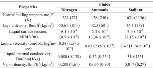
Table 1 shows acceptable values for different properties of working fluids
Satellite Thermal Management
If motions of two bodies are considered in an inertial frame for reference, solely due to the mutual force of gravitation between two bodies, the path of one body is relative to other is a conic section (circle, ellipse, parabola, or hyperbola). The first body, relative to which the motion of the second body is considered, is called the primary body and the secondary body is called a satellite (of the primary body).
The equation of motion of a two-body probe is given as
r̈1= − μ
1r r2
Where,
μ= G(m + m )
And is called as the gravitational parameter, G refers to universal gravitational constant and m1 and m2 are masses of
two bodies where r is the position vector.
The primary body lies at one of foci of the conic section that describes the path of the secondary body (satellite) relative to the primary body. The path of the secondary body is called an orbit.
The most “obvious” examples of one body orbiting another are Sun-Earth system and Earth-Moon system. In both cases, the orbiting body, Earth in the former and Moon in the latter, are called natural satellites. Objects or bodies placed into orbits around natural heavenly bodies by human beings are called artificial satellites. In present work, the word “satellite” refers to an artificial satellite unless otherwise specified Robert D. Karan, (1998).
Maximum priming height which can obtain by a capillary is expressed by equation.
h + h = σ cosθ
ρ −ρ g∗ ( 1
r +
1
r )
Where, h = vertical height to the base of the artery, hc = vertical
height to the top of the artery, rp1 = first principal radius of
curvature of the priming meniscus, rp2 = second principal radius
of curvature of the priming meniscus.
The maximum heat transfer due to the entrainment limit can be obtained from
Q = π r L 2πρ σ/z
Table 1Properties difference of cryogenic,
moderate-temperature and fluid metal heat pipes at normal boiling conditions Robert D. Karan, (1998).
Properties Fluids
Nitrogen Ammonia Sodium
Normal boiling temperature, F
(K) -321 (77) -28 (240) 1621 (1156)
Liquid density, lbm/ft2(kg/m3) 50.61 (811) 42.5 (681) 46.1 (739)
Liquid surface tension, lbf/ft(N/m)
6.1 x 10⁻⁴
(8.9 x 10⁻³)
2.3 x 10⁻³
(3.36 x 10⁻²)
7.9 x 10⁻³
(1.15 x 10⁻¹)
Liquid viscosity lbm/ft-hr(kg/m
-sec)
0.38 (1.57 x
10-4) 0.65 (2.69 x 10
-4) 0.42 (1.74 x 10⁻⁴)
Liquid thermal conductivity,
Btu/lbm(J/kg) 0.080 (0.138) 0.32 (0.554) 31.8 (55)
International Journal of Recent Scientific Research
Where z = characteristic dimension of the liquid interface
The degree of superheat to result nucleation expressed by
∆T =3.06σ T
Where = Thermal layer thickness, ∆T = elevated temperature at 850C
To find minimum flow area, we can equate the maximum capillary pressure to the sum of the liquid and gravitational pressure drops as follows
∆ = ∆ + ∆
Thermal conductivity of the wick can be found and used in the steady state conduction.
k = β−ε
β+ ε k
Also thermal conductivity of the wick i employing the relation
k = (1 −ϵ)k +ϵk
Where kf = is the thermal conductivity of the working substance.
The wick-wall interface equivalent heat transfer coefficient is evaluated using
h = k
k r log rr
Pressure loss in the condenser and evaporator is expressed
by ∆P = K ∗ l Q/2KA
Where, l = effective circumferential flow which is equal to πr /4
Capillary pressure generated is given by Marcus, B.D (April 1972)
∆P = 2σcosθ/r Need
If the temperature limits of the satellite is maintained to a limit which it was designed and assembled for, then the operation of the satellite will be better and thus the performance of the satellite also. Thus for this the thermal management of the satellite system is very important. Thus satellite thermal management must start with establishing thermal specifications in which the satellite present in its various stages of its life for overcoming the obstacle of thermal control after which can be proceeded further.
Heat pipes in satellite
The only mode of heat rejection in a satellite is by radiation to deep space (2.73K). Heat dissipating components on a satellite are placed on thermal radiators that can reject heat by radiation.
International Journal of Recent Scientific Research Vol. 9, Issue, 10(D), pp. 29324-29328, October 2018
dimension of the liquid-vapor
The degree of superheat to result nucleation expressed by
= elevated temperature
To find minimum flow area, we can equate the maximum capillary pressure to the sum of the liquid and gravitational
Thermal conductivity of the wick can be found and used in the
Also thermal conductivity of the wick is approximated
is the thermal conductivity of the working substance. wall interface equivalent heat transfer coefficient is
condenser and evaporator is expressed = effective circumferential flow which is equal to
Capillary pressure generated is given by Marcus, B.D (April
If the temperature limits of the satellite is maintained to a limit which it was designed and assembled for, then the operation of the satellite will be better and thus the performance of the satellite also. Thus for this the thermal management of the Thus satellite thermal management must start with establishing thermal specifications in which the satellite present in its various stages of its life for overcoming the obstacle of thermal control after which can be
The only mode of heat rejection in a satellite is by radiation to deep space (2.73K). Heat dissipating components on a satellite are placed on thermal radiators that can reject heat by radiation.
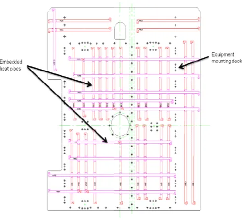
Figure 2 Embedded he
Figure 2. Indicates equipment deck of heat pipe in satellite with an objective of removing heat from satellite electronic source.
Thermal Modeling and Analysis
Three principal heat pipes and six spreader heat pipes are considered for design and analysis. Each main heat pipe has two electronics units mounted on one side. The heat dissipation in electronics 1 is 50W and in electronics 2 it is 25 W. The overall size of the deck is 1m x 0.5 m.This configuration of the deck is shown in figure 3.
Figure 3 Equipment deck
Thermal radiator area of size 950 mm x 500 mm is provided on the other end of the deck. The remaining portion of the deck is provided with multi-layer super
loses if so.
Figure 4 Heat pipe dimensions
29328, October 2018
Embedded heat pipes in satellite
Figure 2. Indicates equipment deck of heat pipe in satellite with an objective of removing heat from satellite electronic
Thermal Modeling and Analysis
Three principal heat pipes and six spreader heat pipes are for design and analysis. Each main heat pipe has two electronics units mounted on one side. The heat dissipation in electronics 1 is 50W and in electronics 2 it is 25 W. The overall size of the deck is 1m x 0.5 m.This configuration of the
Equipment deck
Thermal radiator area of size 950 mm x 500 mm is provided on the other end of the deck. The remaining portion of the deck is layer super-insulation to prevent any heat
Prashanth H.K and Nagesh Kumar R
A thermal model domain is developed by using in Siemens NX 8.5 and steady-state thermal analysis is done to estimate the temperatures and temperature balance of the heat pipe zone.
Table 2 Input parameters for analysis
Parameter Va
Deck size 1.50 m x 0.50 m
Deck thickness 13 mm
Deck skin thickness 0.3 mm
Deck material Aluminium alloy
Deck out of plane
conductivity
1.5 W/m K
Heat pipe cross section 13 mm x 13 m
Heat pipe type & casing material
Axially grooved ammonia heat aluminium alloy
Length of heat pipe 1.5 m
Electronics 1 heat dissipation 50 W Electronics 2 heat dissipation 25 W
Radiator emittance 0.88
Sink temperature 2.73 K
The parametric values selected for analysis is given in table 2. This uses aluminum alloy as deck material and ammonia as an operating fluid.
A
B
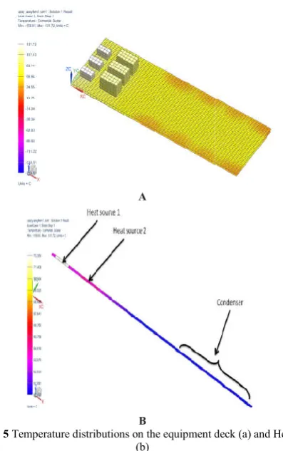
Figure 5 Temperature distributions on the equipment deck (a) and Heat pipe (b)
Temperature distribution of the heat pipe and deck is shown in figure 5(a) and 5(b) respectively. Above figures shows the distribution of the temperature on the heat pipe where major concentration of this analysis goes towards the evaporator and condenser section, as we can see there is a large quantity of temperature is concentrated at the heat source 1 and 2(evaporator) and least quantity of temperature in the condenser region.
The equations were solved in SCILAB for n=0 to 200. The heat pipe length is subdivided in 10 equal nodes for the ease of analysis.
and Nagesh Kumar R., Design, Modeling And Analysis of Heat Pipe For Space Application
A thermal model domain is developed by using in Siemens NX state thermal analysis is done to estimate the temperatures and temperature balance of the heat pipe zone.
Input parameters for analysis Value
Axially grooved ammonia heat pipe,
The parametric values selected for analysis is given in table 2. aluminum alloy as deck material and ammonia as an
Temperature distributions on the equipment deck (a) and Heat pipe
Temperature distribution of the heat pipe and deck is shown in respectively. Above figures shows the distribution of the temperature on the heat pipe where major concentration of this analysis goes towards the evaporator and condenser section, as we can see there is a large quantity of the heat source 1 and 2(evaporator) and least quantity of temperature in the
The equations were solved in SCILAB for n=0 to 200. The heat pipe length is subdivided in 10 equal nodes for the ease of
Temperature of wall distribu
Analytical model analysis is shown in figure 6.
Figure 6 Temperature distribution at wall from analytical model of heat pipe
The above figure shows and it is clear that the temperatures are higher at heat source 1(50W) and heat source 2 (25W) and the slope decreases gradually as the temperature decreases and reaches the minimum i.e. at the condenser section.
CONCLUSION
A technical approach is done for developing model of heat pipe with two heat input sources whi
satellite which is discussed here in with. Results for analytical model are developed for in comparison with the system level model. The present work uses idea of mathematical model presented by Shabgard and Faghri to esti
condition of the heat pipe under steady
According to the model developed, analysis done, this model can be used in optimal way for effective thermal management for space applications like satellite, space ships, celesti technical objects etc.
Scope of Future Work
In future continuation of the present work, liquid and vapor flows have to be modeled in addition to temperature profiles to get a complete understanding of the processes taking place in the heat pipe, Further, several other models available in literature can be applied to analyze the operating condition of heat pipes in similar applications. Further, experimental validation of the results obtained by analysis can be carried out.
References
1. Hamidreza Shabgard and Amir Faghri, (June 2011), “Performance characteristics of cylindrical heat pipes with multiple heat sources’’, Applied thermal engineering, Elsevier Ltd. pp
2. Faghri and Buchko,
numerical analysis of low temp multiple heat sources’’,
Vol. 113, ASME.
3. Grooten, (January 2007), towards an optimal design of heat pipe equipped heat exchangers, Klima, Report number WPC2007.01
4. Jentung Ku, (2015), Introduction to Hea Goddard Space Flight Center
5. Robert D. Karan, (1998), ‘Satellite thermal control for system engineers’, Vol.181, ISBN 1
Design, Modeling And Analysis of Heat Pipe For Space Application
Temperature of wall distribution from the system level Analytical model analysis is shown in figure 6.
Temperature distribution at wall from analytical model of heat pipe
The above figure shows and it is clear that the temperatures are 1(50W) and heat source 2 (25W) and the slope decreases gradually as the temperature decreases and reaches the minimum i.e. at the condenser section.
A technical approach is done for developing model of heat pipe with two heat input sources which is used in thermal radiator of satellite which is discussed here in with. Results for analytical model are developed for in comparison with the system level The present work uses idea of mathematical model presented by Shabgard and Faghri to estimate the operating condition of the heat pipe under steady-state operation.
According to the model developed, analysis done, this model can be used in optimal way for effective thermal management for space applications like satellite, space ships, celestial
In future continuation of the present work, liquid and vapor flows have to be modeled in addition to temperature profiles to get a complete understanding of the processes taking place in Further, several other models available in literature can be applied to analyze the operating condition of heat pipes in similar applications. Further, experimental validation of the results obtained by analysis can be carried out.
Shabgard and Amir Faghri, (June 2011), “Performance characteristics of cylindrical heat pipes with multiple heat sources’’, Applied thermal engineering, Elsevier Ltd. pp-3410-3419.
Faghri and Buchko, (1991), “Experimental and numerical analysis of low temperature heat pipe with multiple heat sources’’, Journal of heat mass transfer, Grooten, (January 2007), towards an optimal design of heat pipe equipped heat exchangers, Klima, Report Jentung Ku, (2015), Introduction to Heat Pipes, NASA/ Goddard Space Flight Center
International Journal of Recent Scientific Research Vol. 9, Issue, 10(D), pp. 29324-29328, October 2018
6. Marcus, B.D, (April 1972), Theory and design of variable conductance heat pipes. TRW Systems Group, NASA CR-2018.
7. Prashanth H.K. (May 2017), “Studies on Operation of Ammonia Heat Pipe with Multiple Heat Sources”-International journal of engineering research in mechanical and civil engineering (IJERMCE-IFERP), ISSN: 2456-1290, Page no. 1053-1060, Volume 2, Issue 5.
8. Torner and M.S. El-Genk, (1994), “A heat pipe transient analysis model’’, Int. J.Heat mass transfer, Vol. 37, No.5, pp-753-762.
9. David Gilmore, (2002), Spacecraft Thermal Control Handbook, the Aerospace Press.
10. Jentung Ku, (2015), Goddard Space Flight Center (GSFC), NASA.
11. Nemec, P, (2009), Influence heat transfer limitations of heat pipes on their cooling power, Zborník prednášok Transcom, ISBN 978-80-554-0031-0.
12. G.F. Marsters, (1972), “Arrays of heated horizontal cylinders in natural convection”, International Journal of Heat and Mass Transfer.
13. Tien C. L., Chang K. S.,(1979), “Entrainment limits in heat pipes”, AIAA Journal, 17, p643-646.
14. A. Alizadehdakhel, M. Rahimi and A. A. Alsairafil, (2010), "CFD modelling of flow and heat transfer in a thermosyphon," Int. Commune. Heat and Mass Transfer, vol. 37, pp. 312-318.
15. Vadakkam, J. Y, (July 2003), Murthy and S. V. Garimella, "Transient analysis of flat heat pipes," in HT2003 ASME Summer Heat Transfer Conference, Las Vegas, Nevada, USA.
16. Tolubinskii, V., Shevchuk, E., Stambrovskii, V., (1978), Study of liquid-metal heat pipes characteristics at start-up and operation under gravitation. 3rd International Heat Pipe Conference, pp. 274e282.
17. Hsu, Y.Y. (August 1962), on the size range of active nucleation cavities on a heating surface. J. Heat Transf., Trans A.S.M.E.
How to cite this article:
Prashanth H.K and Nagesh Kumar R.2018, Design, Modeling and Analysis of Heat Pipe For Space Application. Int J Recent Sci Res. 9(10), pp.29324-29328. DOI: http://dx.doi.org/10.24327/ijrsr.2018.0910.2838
![Figure 1 Conceptual working of heat pipe [Source: Jentung Ku, 2015]](https://thumb-us.123doks.com/thumbv2/123dok_us/200347.2014235/1.595.320.561.629.750/figure-conceptual-working-heat-pipe-source-jentung-ku.webp)