*Corresponding author:Moyeed Abrar ISSN: 0976-3031
Research Article
INTERFACING A SERVOMOTOR WITH ARDUINO UNO MICROCONTROLLER
Moyeed Abrar*
Department of Computer Science & Engineering, Khaja Banda Nawaz
College of Engineering, Kalaburagi, Karnataka, India
DOI: http://dx.doi.org/10.24327/ijrsr.2019.1002.3172
ARTICLE INFO ABSTRACT
Arduino aims to provide a low cost and simple and easy path for the users to use devices that interact with the environment with the help of sensors and actuators such as in motion detectors and robotics etc. Servo motors are in limelight owing to their tremendous electrical performance and hence are being used in various applications. Servomotors have high torque capabilities. Servomotors are also known as control motors. Unlike large industrial motors, they are not used for continuous energy conversion but only for precise speed and precise position control at high torques. The main objective of this paper is to experimentally demonstrate the interfacing of a servomotor with the Arduino uno microcontroller board. The paper also emphasizes the working of servomotors and its salient features.
INTRODUCTION
The Arduino board was designed to adapt to new requirements and challenges for students to build projects in embedded domain as well as in Internet of Things (IoT) applications. It is essentially an open source platform which possesses a microcontroller and a part of the software or Integrated Development Environment (IDE) which runs on the PC used to write and upload the computer code to the physical board. In order to program a new code on the board using Arduino a USB cable can be used, unlike other boards.
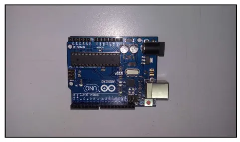
The Arduino Uno is a microcontroller board which is widely used among various other Arduino boards. The uno is the latest in a series of USB arduino boards and the reference model for Arduino platform. This microcontroller board is based on the ATmega 328. There are 14 digital input/output pins, out of which 6 can be used as PWM outputs. The microcontroller board also has 6 analog inputs, a 16MHz crystal oscillator, a USB connection, a power jack, an ICSP header and a reset button.
An external power supply is generally used to power the arduino. The Arduino can also be powered via the USB connection. The power source is selected automatically. An AC to DC adapter or battery is the external (non USB) power to the Arduino. An external supply of voltage 6 to 20 volts is
used to operate the board. However the recommended range is 7 to 12 volts.
With respect to communication, Arduino uno has a wide range of facilities which allows Arduino uno to communicate with a computer, another Arduino or with other microcontrollers. The ATmega 328 UART TTL provides 5 volt serial communication, which is available on digital pins 0 (RX) and 1 (TX) (A data sheet on Arduino Uno R3). The Arduino software includes a serial monitor which allows simple textual data to be sent to and from the Arduino board. The RX and TX LEDs on the Arduino uno board will flash when data is being transmitted via the USB to serial chip and USB connection to the computer (but not for serial communication on pins 0 and 1).
The Arduino uno used in the proposed work is illustrated in figure 1.
International Journal of
Recent Scientific
Research
International Journal of Recent Scientific Research
Vol. 10, Issue, 02(E), pp. 31010-31014, February, 2019
Copyright © Moyeed Abrar, 2019, this is an open-access article distributed under the terms of the Creative Commons Attribution License, which permits unrestricted use, distribution and reproduction in any medium, provided the original work is properly cited.
DOI: 10.24327/IJRSR
CODEN: IJRSFP (USA)
Article History:
Received 4th November, 2018
Received in revised form 25th December, 2018
Accepted 18th January, 2019 Published online 28th February, 2019
Key Words:
Figure 1 Photographic view of Arduino uno board
The table 1 illustrates the technical specifications of Arduino uno.
Table 1 Arduino uno Technical specifications
Sl. No Specifications
1. Microcontroller : ATmega 328 2. Operating voltage: 5Volts
3. Input voltage(Recommended): 7volts to12 volts 4. Input voltage(limits): 6 volts to 20 volts
5. Digital I/O Pins: 14 of which 6 provide PWM output. 6. Analog input pins: 6
7. DC current per I/O Pin: 40mA 8. DC current for 3.3 volt pin : 50mA
9. Flash memory: 32KB of which 0.5Kb used by boot loader
10. SRAM: 2KB 11. EEPROM: 1KB 12. Clock speed: 16MHz
Servomotor Overview
As servomotor provides precise angular precision, which means it can rotate as per the desire of the user and then stop and wait for the succeeding signal to take further action. Hence, it is widely used. Servomotor differs from a standard electrical motor mainly because a standard electrical motor turn ON as soon as power is applied to it and continues to rotate as power is switched OFF. In an electrical motor only the speed of rotation can be controlled and it can be turned ON and OFF but its rotational progress cannot be controlled. Servomotor is a very versatile and a special kind of motor whose operation is automatic up to a certain limit for a given command in order to correct the performance with the help of error sensing feedback. Hence for applications where rotation of motor is required for just a certain angle, servomotor is used which has special arrangement which makes it to rotate at a certain angle for a given electrical input.
Servomotor is controlled with the help of servomechanism. Servomotor can be a DC servomotor or an AC servomotor. A DC servomotor is one where the motor as a controlled device associated with servomechanism is a DC motor. On the other hand an AC servomotor is one where the AC operates the controlled motor.
Principle of operation of servomotor
Servomotor works on the principle of servomechanism. A servo system mainly consists of three components namely a controlled device, an output sensor and a feedback system. With respect to a servomotor implementing servomechanism is nothing but an automatic closed loop control system. Here the device is controlled using feedback signal generated by
comparing an output signal and reference input signal instead of controlling the device by applying the variable input signal.
When the command signal or the reference input signal is given to the system, it is compared with the output reference signal it is compared with the output reference signal of the system which is generated by the output sensor and the third signal produced by the feedback system. Here the third signal behaves as an input signal of the controlled device. The fundamental task of the servomechanism is to maintain the output of the system at the desired value in the presence of disturbances.
The motor operation is controlled in closed loop for a system built with servo drives and servomotors. In a servomotor the torque, speed or actual position is fed back to compare the command value and calculate the following errors between them. This error information is then used by the servo drive which corrects the operation of servomotor in real time. This cycle of feedback, error detection and correction is termed as closed loop control. This closed loop control is processed by either of servo drive or motion controller or both depending on the required control. The required operation is achieved by using the control loops for position, speed and torque independently. The three control loops are not always required for all applications. In some of the applications, only the control loop for torque control will be used. However in other applications current and speed for speed control is needed. And furthermore, still in other applications three control loops for position control are required. Their power ratings vary from a fraction of a watt up to a few 100W. Because of their low inertia they have high speed of response. Hence they are smaller in diameter but longer in length. Generally they operate at very low speeds or sometimes zero speed (Arifur Rahman et al, 2018).
Servomotors are used in diversified applications such as radar, tracking and guidance systems, process controllers, computers and machine tools. In the current era both DC and AC servomotors are used.
Following are the Salient Features of SERVOMOTORS
They produce high torque at all speeds including zero speed.
They possess the ability of holding a static position (no motion)
They do not overheat at standstill or lower speeds.
They are capable of reversing directions quickly due to low inertia.
They have the ability to return to a given position time after time without any drift.
They possess the ability to accelerate and decelerate quickly.
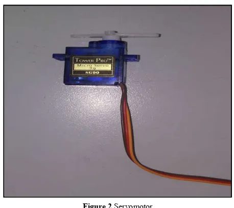
The range of the servomotors angular motion is usually dictated by the pulse width. To set the servomotor to its neutral position of 450, typically a servo pulse width of 1. 5 milliseconds is required, to set the servomotor angle to 00 typically a pulse width of 1.25 milliseconds is needed, likewise to set the servomotor angle to 900 typically a pulse width of 1.75 milliseconds is required (Mark Geddes et al, 2017).The servomotor used for the proposed work is shown in figure2.
Figure 2 Servomotor
METHODOLOGY AND SYSTEM DESIGN
Hardware design
The circuit schematic for the interfacing of servomotor with Arduino uno microcontroller is depicted in figure 3
Figure 3 Circuit schematic of the interfacing
System Specifications
The system specifications for the proposed system is illustrated in table 2
Table 2 Proposed work system specifications
Sl.no Specifications
1. Domain: Microprocessors and Microcontrollers
2. Arduino family: Arduino Uno
3. Servomotor : Tower pro SG 90 9g servomotor
4. Software: Arduino IDE (Integrated Development
Environment)
5. Laptop computer: Pentium, 2GB RAM, processor speed
2.6GHz
6. Aduino uno microcontroller: ATmega 328.
7. Applications: Control of servomotor
8. Jumper wires
9. USB type A to type B cable
Experimental setup
The experimental set up was done in Microprocessors and Microcontrollers laboratory. The hardware connections were made as per the circuit schematic. The required hardware in the form of Arduino uno microcontroller board and servo motor was taken. Basically three wires are needed to control the servomotor namely the ground wire, power wire and the signal or control wire. The ground wire is usually black in color and sometimes brown colored wire is also used as ground wire. The wire used for power is red in color and the signal or control wire is typically orange, yellow or white in color. The red wire and the brown wire of the servomotor were connected to the +5V and ground power pins of the Arduino uno board. The orange wire was connected to digital pin 3 (pulse width modulation) of the Arduino uno board (Mark Geddes et al, 2017). The connections between the Servomotor and the Arduino uno board are depicted in table 3.
Table 3 Hardware connections between servomotor and Arduino uno board
Sl. No Servomotor Arduino uno
1. Red wire (Power) +5V
2. Brown wire (power) GND 3. Orange wire
(control) Pin 3
The required power supply to the system was supported to the USB cable instead of an external power supply. For the software implementation the Arduino IDE (Integrated development environment) software was used. First the Arduino IDE software was installed on the laptop desktop which is open source software (Marko Savaljek et al, 2015). The Arduino IDE software located on the laptop desktop was opened by double clicking on it. The window for writing the program was displayed as shown in figure 4.
Figure 4 Window for sketch writing
Figure 5 Arduino uno board selection
In order to ensure the communication between Arduino uno and the laptop go the tools and then to the port and then select the Arduino uno port option which in this case is com4 as shown in figure 6.
Figure 6 com4 port for Arduino
For programming using the Arduino there are two basic functions namely void setup and void loop. The void setup function is executed only once when the program is executed whereas the void loop function is executed in loop format. In the void setup function the pins of the I/O (Input/Output) devices that are connected to the Arduino are declared. In the void loop function the main code for the required purpose is written which will make the externally I/O devices function accordingly.
Another important feature was the use of servo library which is inbuilt/ by default in the Arduino uno software. Servo library is a library that makes an arduino board to control RC (radio control) servomotors. Servos are equipped with integrated gears and a shaft which can be controlled precisely. In case of Standard servos the shaft is allowed to position at various angles which is usually between 00 to 1800, whereas continuous rotation servos allow the shafts rotation to be set at various speeds (Petru Virlan et al, 2017).
RESULTS AND DISCUSSION
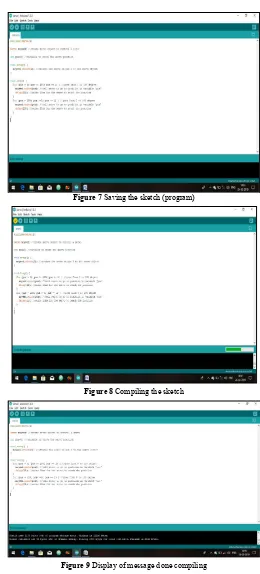
The sketch (program) for the interfacing of servomotor with the Arduino uno was written using embedded C language and then saved as depicted in figure 7. Next the sketch was compiled by clicking on the verify symbol located below the menu bar as
illustrated in figure 8. The message done compiling was shown at the bottom of the window as depicted in figure 9.
Figure 7 Saving the sketch (program)
Figure 8 Compiling the sketch
Figure 9 Display of message done compiling
The USB type A to type B cable was taken and the Arduino uno microcontroller board was connected to the laptop port with this cable. After successfully making these connections the upload icon located on the toolbar was clicked.
Figure 10 Display of compiling sketch message
Figure 11 Display of uploading message
As the code was successfully uploaded the LEDs located near pin 13 (RX and TX) blinks twice. When this happens the servomotor starts rotating. The complete photographic view of the output obtained is illustrated in figure 12.
Figure 12 Photographic view of output obtained
From the output it was observed that the motor rotated from 00 to 1800 and waited for 15mili seconds and then again rotated from 1800 to00. This is evident from the for loop used in the sketch for rotation from 00 to 1800 then the use of delay function to wait for 15 mili seconds and again the use of for loop for the rotation from 1800 to 00.
To stop the rotation of the servomotor the USB type A cable connected to the USB port of the laptop should be disconnected or else the USB type B cable from the Arduino uno board should be carefully removed.
CONCLUSION
In this paper the interfacing of a servo motor with the Arduino uno microcontroller was presented. As a result of this interfacing the servo motor was found rotating. Care was taken in properly connecting the required hardware connections. The Arduino uno with its versatile features and simple hardware configuration makes it easier to interface the servo motor with it. The entire system for the interfacing is very simple to implement, easier to use and is reliable. Programming with Arduino is very simple which makes it relatively easier for interfacing as compared to other microprocessors and microcontrollers. Apart from servo motors, various other motors such as stepper motor, DC motor etc. can be interfaced with the Arduino uno.
References
1. B.L. Theraja, A.K. Theraja, A Textbook of Electrical Technology: AC and DC Machines, twenty third revised multicolored edition, Volume II, New Delhi,1562-1565, (2015).
2. Mark Geddes, Arduino project handbook, 25 Simple Electronics Projects for Beginners, San Francisco, volume 2, no starch press William Pollock publisher (2017).
3. Marko Savaljek, Arduino Succinctly, Syncfusion.Inc, 2015 USA.
4. A datasheet on Arduino Uno R3, Future Electronic Corporation
5. S. Angalaeswari, Amit Kumar, Divyanshu kumar, Shubham Bhadoriya, Speed control of permanent magnet (PM) DC motor using Arduino and Lab VIEW, 2016 IEEE International Conference on Computational Intelligence and Computing Research (ICCIC), Chennai, India.
6. Petru Virlan, Direct and reverse start of the servomotor with Labview, 2017 International conference on Electromechanical and power Systems (SIELMEN), Iasi, Romania.
7. Norlela Ishak, Nor Iadayu Abdullah, Mohd Hezri Fazalul Rahiman, Abd Manan Samad, Ramli Adnan, Model identification and controller design for servomotor, 2010 6th International colloquium on signal processing & its Applications, Mallaca city, Malaysia. 8. Terentiev, Povernov, Sypin, The direct current
servomotor control system, 2004 International workshop on Electron Devices and Materials, Erlagol, Altai, Russia.
9. Arifur Rahman, Assignment on Servomotor, technical report January 2018