SAL: Scaling Data Centers
Using Smart Address Learning
Alexander Shpiner
1, Isaac Keslassy
1, Carmi Arad
2, Tal Mizrahi
1,2, and Yoram Revah
21
Technion,
{
shalex@tx, isaac@ee
}
.technion.ac.il
2Marvell Israel,
{
carmi, talmi, yoramr
}
@marvell.com
Abstract—Multi-tenant data centers provide a cost-effective many-server infrastructure for hosting large-scale applications. These data centers can run multiple virtual machines (VMs) for each tenant, and potentially place any of these VMs on any of the servers. Therefore, for inter-VM communication, they also need to provide a VM resolution method that can quickly determine the server location of any VM. Unfortunately, existing methods suffer from a scalability bottleneck in the network load of the address resolution messages and/or in the size of the resolution tables.
In this paper, we propose Smart Address Learning (SAL), a novel approach that expands the scalability of both the network load and the resolution table sizes, making it implementable on faster memory devices. The key property of the approach is to selectively learn the addresses in the resolution tables, by using the fact that the VMs of different tenants do not communicate. We further compare the various resolution methods and analyze the tradeoff between network load and table sizes. We also evaluate our results using real-life trace simulations. Our analysis shows that SAL can reduce both the network load and the resolution table sizes by several orders of magnitude.
I. INTRODUCTION
Multi-tenant data centers provide an increasingly popular solution for hosting large-scale service applications [1]. Their appeal comes from their scalability, since they are increasingly cost-effective as they get larger [2]. To ensure scalability, data center providers run multiple virtual machines (VMs) per data center, and can allocate the VMs of a client application to multiple servers, thus also achieving load balancing, fault tolerance and power saving. For efficient implementation of these features, the network has to support unbounded VM placement and migration such that any VM is able to be assigned to any server. In particular, it must provide resolution of the VM location for inter-VM communication: when a new connection is created between two VMs, the initiating VM needs to retrieve the location of the other VM. The services for the physical location resolution of the logical entities have to be supplied by the data center network infrastructure, e.g. by network probing, by the forwarding tables, or by some level of indirection relying on a central database.
Unfortunately, existing location resolution methods often suffer from scalability issues, especially with the resolution network load and the forwarding table size. This is because the network load of the resolution request broadcast messages increases with the number of VMs [3], [4], while it should be kept low in order to leave bandwidth for the application data communication. Moreover, the forwarding-table entries needed
for the ever-increasing number of VMs would not fit anymore the on-chip memory that is needed to allow fast access and update times [5], [6]. These issues get especially acute as data centers grow, and may become critical in future multi-tenant data centers, which are expected to include millions of VMs [1], [2].
Several architectures have been proposed to break this scala-bility bottleneck by usingoverlay networks[3], [7]–[12]. These architectures partition the data center network into segments of broadcast domains, thus solving the problem for intra-segment VM communication given fixed segment sizes. In addition, these architectures use network devices called edge bridges
to connect between the segments and the network core. The edge bridges provide address resolution for inter-segment VM communication. They can be implemented either in the server hypervisors or at the top-of-rack switches. Unfortunately, they still do not solve the scalability problem of inter-segment address resolution. In fact, [4], [12], [13] state that the overlay network may still suffer from a bottleneck in resolving target stations physical address (MAC or IP) at the overlay edge gateway nodes within the data center. The address resolution broadcast storms may even cause loss of traffic if the cache is too small, and may consume significant bandwidth at large networks.
In this paper, we propose a new address resolution approach calledSmart Address Learning(SAL). SAL enables scaling the data center while keeping both the resolution table sizes and the network load low. To do so, we use the fact that VMs of different tenants do not communicate directly. Thus, the edge-bridge resolution tables only need to learn addresses of the VMs that belong to the tenants they serve. For instance, if an edge bridge serves a local network with VMs of a tenanti, it only needs to follow the location of the other VMs of tenant
i, and can ignore the resolution information of VMs of any tenantj6=i. This selective learning makes the table usage more efficient and increases its hit rate. In addition, SAL decreases the network load, because the VM location updates are only sent to the tables that serve the same tenant, instead of being flooded.
trigger of address learning.
We further provide an analytical model for the evaluation of the table sizes and the network load under SAL and other resolution methods. In addition, we compare SAL against alternative methods using simulations based on synthetic as well as real-life VM creation, placement and tenancy traces. Due to the publication page limits, extended duscussions, analysis, proofs and simulations are provided in [14].
To our knowledge, this paper is the first to introduce a model for comparing address resolution methods in data centers, as well as the first to evaluate them using real-life trace simula-tions.
Our analytical model and simulation results show that SAL can reduce the network load for a given resolution table size by up to four orders of magnitude. It also yields a lower update rate and a higher hit rate in the resolution table, thus potentially enabling implementation of fast on-chip resolution tables even for large multi-tenant data centers.
II. RELATEDWORK
In recent years, several overlay network architectures have been proposed to break this limitations in the data centers [3], [7]–[11]. In these architectures, the VM packets are encapsu-lated in (or rewritten with) the overlay network headers. The overlay network header is used to route the packet through the network core, which can be implemented using various routing protocols such as commodity Ethernet, hierarchical IP routing, TRILL or MPLS. The encapsulation point, denoted edge bridge, can be for instance the server hypervisor or the top-of-the-rack switch.
The overlay methods can be roughly divided into three categories:
Central database — The central database approach is used in VL2 [7] and Portland [10]. The distributed hash table on the aggregation switches, as used in SEATTLE [9], also relates to this category. In this approach each VM location is listed in a unique central consistent database. The edge bridge resolves the location by sending a unicast request message to the consistent directory. Note that the edge bridges also hold a cache table that lists the recently-used resolution entries. The usage of a central address resolution database has several drawbacks. These methods may have scalability problems in large data centers due to frequent resolution updates, unbal-anced request rates, fault-tolerance issues, and longer delays for retrieving the information. For instance, [10] states that for maintaining the resolution requests, approximately 70 pro-cessing cores are needed, which is beyond the capacity of a single commodity machine. VL2 [7] replicates the database to multiple cached servers. However, this raises consistency and concurrent-replication issues, as well as potential scalability problems when the update rate is high. Moreover, it requires maintaining additional servers for backing up the data. It is also vulnerable to malicious attacks, which lead to service unavailability if the fabric manager fails to perform address resolution [15]. In addition, SEATTLE [9] presents potential fault-tolerance weakness, because the mapping DBs/switches
are not backed up, and in a case of DB/switch failure, all the associated mapping information is lost. DHT replication is possible, but generates additional complexity [16].
We next examine two distributed approaches:
Pull — The distributed Pull approach does not rely on a consistent database, but on broadcasting resolution request messages over the network and learning the resolution from the reply. The address resolution is pulled on-demand, meaning, at the time the resolution is required at the edge bridge. This approach is used in EtherProxy [3] and several other architectures. Unfortunately, this broadcasting may evolve into a vast flooding of the data center network core, and therefore cause a prohibitive network load. Note that here as well, the edge bridges may hold a cache table that lists the recently used resolution entries, and attempt to store entries for the active connections. However, these entries may be inconsistent. Initial VXLAN [8] implementations configured multicast groups per tenant, and broadcasted the address resolution request over the tenant multicast group only. However, the network devices failed to support the large required number of multicast groups. Thus, the VXLAN address resolution was moved to be central-DB-managed in latter implementations [17].
Push — The distributed Push approach relies on sending address resolution updates with each location change. The edge bridges learn the VM addresses at each location update, and manages resolution tables at the edge bridges. Thus, it avoids request broadcasting, but requires larger resolution tables. Keeping the location information consistent and close to the VM allows for a faster start-up time of the new connections and a lower network load. For instance, this approach is used in Netlord NL-ARP address learning approach [11]. Netlord repli-cates the resolution database on every server, and therefore uses a maximal possible number of entries. The edge bridge sends an update message upon every change of the VM status that it is responsible of, similarly to the gratuitous ARP mechanism. Unfortunately, in order to be efficient, this approach requires large tables. Note that if the table capacity is large enough and the update messages always arrive within a negligible time, the push architectures tables are always consistent. Usually, the Push approach is combined with the Pull approach for resolving cases with resolution table inconsistency due to table overflow or resolution packet losses.
In summary, both current centralized and distributed address resolution approaches in the data center have limited scalability when the number of VMs increases.
As mentioned before, our suggested approach is based on selective learning of addresses from the incoming resolution request messages. A similar idea is used in the selective ARP learning [18], where an ARP table is configured to learn a pre-configured specific set of IP addresses. However, the selective ARP learning approach uses only a passive filtering, without dynamic adaption to VM re-placement and to tenancy.
III. NETWORKMODEL ANDASSUMPTIONS
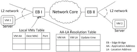
Fig. 1. Network Model. The edge bridge (EB) connects the VMs in its L2 network to the other VMs through the data center network core. The EB implements overlay network encapsulation. It uses two tables for the address resolution. The first is a consistent table that lists all the local VMs under the EB, while the second lists the address resolution of the VMs outside the network under the EB. In the paper, we focus on the scalability of the second table.
literature [3], [7], [10].
We use the terms application address (AA) and location address (LA) to define both the addresses in the user VM address space and in the physical data center address space, respectively [7]. By the termresolutionwe further refer to the translation of the AA address of a VM into its LA address.
We denote as an edge bridge (EB) the encapsulation point where the inter-VM data packets are encapsulated in (or rewrit-ten with) the overlay data center network header. In general, the encapsulation point can be either the ToR switch, the aggregation switch, or the server hypervisor. We assume for simplicity that the communication inside the local network under the EB is L2-protocol based, but other methods would hold as well.
Furthermore, broadcast ARP-request messages that are in-jected by a VM are stopped at the EB and do not propagate to the core network. For the address resolution requests for VMs outside the L2 network, the EB replies using an ARP-reply message with its own MAC address. This common approach is also used by many other overlay network architectures [3], [7], [10].
Our model supports any common network core protocol and topology. The routing between the EBs can be implemented using standard IP routing with ECMP, MPLS or TRILL tunnels, layer-2 Ethernet with VLANs , or any other protocol, as long as each EB can communicate with each other EB.
Each edge bridge stores an LA-to-AA resolution tableand a localforwarding table. The LA-to-AA resolution table is used to resolve the destination AA for a given LA. The next section introduces SAL, a novel learning scheme for the resolution entries. In addition, the local forwarding table lists the AAs of all the VMs under the edge bridge layer-2 network together with their layer-2 MAC addresses and the output port towards them. We assume that the placement controller of the data center keeps the forwarding table consistent.
The resolution tables in our model avoid using the time-out mechanism for the entries. The old, last recently used, inconsistent entries are overwritten, when a new resolution information is required to be written to a full memory.
Finally, in the multi-tenant environment, the VMs are divided into groups of tenants. The VMs of a tenant are assumed to
communicate only between themselves, and possibly with hosts outside of the data center, but not with VMs of other tenants. This is logical, since they belong to different applications. It also makes sense for security isolation. Therefore, VMs typically only communicate with a small number of other VMs [9], [19], [20]. We will leverage this assumption in the paper to reduce the amount of information that needs to be stored in the resolution tables. For simplicity, we start by focusing on internal VM-to-VM communication in this paper, and neglect the communications to hosts outside of the data center. We later discuss how the inter-tenant communication support can be implemented with our approach.
IV. SMARTADDRESSLEARNING(SAL)
A. SAL Overview
This section presents our suggested Smart Address Learning (SAL) approach. SAL implements a distributed resolution database, in which the resolution tables are stored on the edge bridges (EBs).
In SAL, the EB resolution tables only store the addresses of the VMs that belong to the tenants of the VMs hosted in the EB network.
More specifically, any EB that broadcasts an address res-olution request message will include the AA and LA of its requesting VM. Upon receiving the message, the other EBs will selectively learn this AA-to-LA mapping in their resolution table if and only if their network contains another VM of the same tenant as the requesting VM. Therefore, EBs without VMs of this tenant can disregard this message, and as a result their resolution can typically be smaller than without this selective learning. The EBs do not need to store any global resolution information.
This section presents how our suggested SAL algorithm updates the EB resolution tables following a VM location update, i.e. following a VM creation, destruction or migration. We consider two variants of the update method:pullandpush. In the pull version, the location information is pulled by the EB when this information is required by the encapsulation process, and is not available in its resolution table. On the other hand, in thepushvariant, the location updates are immediately propagated to other forwarding databases on selected EBs.
Intuitively, the pull version is preferable when the location update rate is high relative to the address resolution request rate, and when pushing the updates through broadcasting is costly. We further analyze the tradeoffs involved in the next sections.
B. Pull Update (On-Demand Update)
VM of the same tenant. Each EB knows which tenant VMs it serves using the information from the local VMs forwarding table.
Note that if a VM is migrated during an active connection, its resolution update can be pushed immediately in order to avoid a communication disruption by the migration process. In addition, due to the inconsistent information in the resolution tables, it may happen that an EB receives a data message that is destined to the VM that was previously hosted in its network, but already migrated from it. Then the EB answers the source EB with an error message, and the source EB will re-initiate the full address resolutions process. Incidentally, an optional alternative implementation for the EB is to redirect the packets to the EB of the updated VM location, and then ask it to inform back the source EB of the new location.
C. Push Update (On-Change Update)
In thepushvariant, the updates are pushed to the resolution tables. In our suggested SAL algorithm, in order to reduce network load, the location update broadcast is replaced with messages (several unicast or single multicast) to selected EBs only.
Specifically, upon VM location change, the update is propa-gated (pushed by either the migration source or the destination EB) immediately only to the EBs that host VMs of the same tenant of the VM. Note that SAL does not require the EB to have a global knowledge on which tenants have clients under each EB, but only the information of tenant VMs that it serves. The destination EBs are known to the sending EB, because it holds the address resolution of all the tenant VMs in its address resolution table. When an update needs to be sent, the EB selects from the forwarding database the location addresses (the destination EBs) of all the VMs of the tenant whose VM is updated. An easy and fast selection can be achieved by assigning application addresses (AAs) that contain the tenant ID in the specific bits, or even better, by logically organizing the table as a tree with a single node per AA, pointing to the different VMs. No additional global information about the VM location is required to be stored.
Special treatment is required in the following two cases. First, when a VM is assigned to an EB network where no other VM of the same tenant exists, the EB needs to retrieve the location information of all other VMs of the tenant. This can be done by broadcasting a request message to all other EBs, or with the assistance of the data center placement controller.
In a second special case, the last VM of a tenant in an EB is removed due to deletion or migration to other EBs. In this case, the EB can remove all the location entries of all other VMs of this tenant in other EBs. This can be done easily by the EB itself, by checking the number of remaining VMs of the tenant in its resolution table after removing a VM.
Inconsistency of the information in the resolution tables may still occur with the push variant. It can happen if the message arrival fails, or if the table is filled up. To overcome this inconsistency, the pull update mechanism is still preserved in the push variant. If the requested entry is missing from the
TABLE I ANALYSISNOTATIONS
N # of EBs 128
V # of VMs per EB 640
T # of tenants 5000
U # of VMs per tenant(≡V N /T) 16 C Active Connections(≤V N(U−1)) 1.2·106
B EB resolution table capacity 105 λc Total VM creation rate (1/sec) 10
λm Total VM migration rate (1/sec) 1
λd Total VM destruction rate (1/sec) 10
λu Total VM location update rate (1/sec)
(≡λc+λm+λd)
21
λs Total resolution request rate (1/sec) 105
resolution table in the EB, a resolution request is broadcasted to all the other EBs.
V. ANALYTICALMODEL
A. Notations and Assumptions
We would now like to compare the various approaches by formally analyzing their performance. Unfortunately, the performance of each approach is sensitive to many parameters, such as the data center topology, the placement policy, the number of tenants, the distribution of VMs per tenant, the rate of VM creations, migrations and destructions, the burstiness of the application changes, and so on. As a result, to gain some insight, we are reduced to providing a first model in significantly simplified settings. In our analysis we compare the following approaches: Central DB, Push with and without SAL, and Pull with and without SAL. Note that in our model, the Central DB results are also valid for the DHT-Based DB.
Table I illustrates the settings for our model. We make several simplifying assumptions. First, we assume equal-sized tenants, with a fixed number of VMs per tenant, and a fixed table capacity at each EB. As well we assume fixed rates of various VM location update events and VM resolution requests, each following exponentially-distributed inter-event times. We further assume links with infinite capacity and zero propagation time. These assumptions are of course somewhat simplistic, yet they help us better understand the tradeoffs involved in the algorithm design.
Additionally, we consider two simple VM placement strate-gies: packed andround-robin. These two placement strategies are two extremes that typically cause the best- and worst-performance cases. Thebest case typically corresponds to the
packed placement, in which VMs of a tenant are locally packed under the lowest number of EBs as possible. This placement is typically chosen to minimize the network load. On the other hand, the worst case typically corresponds to theround-robin placement, in which VMs of a tenant are spread equally among the servers. This placement strategy may be chosen for its fault-tolerance properties.
TABLE II
NETWORKLOAD UNDERROUND-ROBINPLACEMENT.
Architecture Network Load under Round-robin Placement
Central DB 2λs(1 − min{1, dV
Te−1
U })(1 − min{1, B V N} +
2(min{1, B V N})
λu
λu+λsN )
Push λu(N − 1) + λsN(1 − min{1, dV
Te−1
U })(1 −
min{1,V NB })
SAL-Push λu(min{U, N} − 1) + λs(N − 1)(1 −
min{1,d
V Te−1
U })(1−min{1, B U·min{V,T}})
Pull λsN(1 − dV /TUe−1)((1 − min{1,V NB }) +
min{1,V NB } λu
λu+λsN
)
SAL-Pull λsN(1 − dV /TUe−1)((1 − min{1,U·min{BV,T}}) +
(min{1,U·min{BV,T}}) λu
λu+λsN
)
B. Network Load
Next we evaluate the network load of the address resolution management packets as a function of VM location updates and address resolution requests rates. The network load is expressed as the rate of address resolution packets. For ease of an evaluation, a single multicast or broadcast packet to k
destinations is counted askpackets.
The network load estimation of the resolution architectures is summarized in Table II, and fully proved and analyzed in [14].
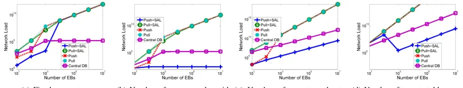
Figure 2 shows the network load as function of number of EBs N in the round-robin placement. We can see that Push with SAL often outperforms the other approaches. Figure 2(b) is especially interesting because it illustrates the scalability of the push version of SAL. It presents the network load as function of number of EBs (N) scaling also the number of tenants (T), such that the ratio N/T is kept fixed.
VI. SIMULATIONS
A. Simulator
We implemented an event-driven simulation of the data center network address resolution system. The simulation in-cludesVM location update events, i.e. creations, migrations and destructions, as well asVM address resolution events, which are initiated by VMs and request for a resolution of other VMs.
We implemented the following address resolution schemes:
Central DB, Push with and without SAL, and Pull with and without SAL. The Pull scheme consists of three variants besides SAL. On the figures they are marked byPull (complete),Pull (connection) and Pull (conservative). The difference between these three Pull schemes is the way in which the EB learns resolution information from the incoming broadcast resolution requests that are not destined to the EB. In Pull (complete), the EBs stores information of each incoming resolution request message. InPull (connection), only the entries that already exist in the resolution table are updated, but no new entry is learned. This method is similar to ARP. Lastly, inPull (conservative), the EB learns only from resolution requests it initiated and the resolution requests that are destined to it.
In all the schemes, the table lengths are limited by a fixed table capacity. When an entry is added to a full table, the oldest entry is overwritten. In addition, an entry with a wrong information is revealed when it is accessed. The wrong entries and the missing entries are resolved by the broadcast resolution request messages to all the servers — except for the Central DB scheme, where the resolution is done by an access to the central directory.
The output of the simulator includes the number of transmit-ted resolution messages, as well as the occupancy, the number of updates, and the hit percentage of the resolution tables. For simplicity, we neglect the impact of the network topology. Thus, each unicast message between a pair of VMs is counted as a single message, and a multicast or a broadcast message is counted as the number of recipients. For example, a request broadcast by an EB in a data center with N EBs is counted as N −1 messages, since it is sent to N −1 EBs; and the unicast reply is counted as a single message. Pulling the address resolution data base in the Central DB architecture is counted as two messages: one for the request and one for the reply. Revealing a wrong entry costs two additional messages: one for sending a packet to a wrong destination, and the second for receiving a reply message indicating that the destination is wrong.
B. Synthetic Trace Simulation Results
We start by running simulations with a synthetically-generated trace. We use the typical values from Table I, and vary the table capacityBfrom10to106entries. The placement distribution is uniform, such that at every placement decision, the edge bridge for each VM is chosen uniformly over all VMs. New VMs pick uniformly their tenants. The VM chosen for migration or destruction are also picked uniformly. At the initial state of the simulations, the data center is full with random VMs up to its capacity (V ·N). The simulations are run until the steady state.
Figures 3(a), 3(b) and 3(c) show the impact of the resolution table capacity on the mean resolution packet network load, the largest mean update rate of a table, and the mean hit rate, respectively, for each of the architectures. Note that for the Central DB, the shown table capacity is for the tables in EBs and not for the central data base. The discussion on the simulation results, as well as additional simulations with real-life benchmark trace is published in [14].
VII. CONCLUSIONS
In the paper we proposed Smart Address Learning (SAL), a novel approach that expands the scalability of current address resolution mechanisms in the data centers, for both the network load and the resolution table sizes, which makes it possible to be implemented on faster memory devices. The key property of the approach is to selectively learn the addresses in the resolution tables, based on the fact that the VMs of different tenants do not communicate.
(a) Fixed parameters. (b) Number of tenants scales with
N.
(c) Number of tenants and rates scale withN.
(d) Number of tenants, table capac-ity and rates scale withN.
Fig. 2. Model of network load vs. number of EBs in a round-robin placement
(a) Network Load vs. Resolution Table Capacity. (b) Largest Table Update Rate vs. Resolution Table Capacity.
(c) Mean Table Hit Rate vs. Resolution Table Capacity.
Fig. 3. Synthetic Event Trace Simulation Results.
and simulations to evaluate the tradeoff of the network load and the resolution table size. Our analysis showed that both the network load and the resolution table sizes can be reduced by orders of magnitude depending on the system parameters.
More generally, to our knowledge, this paper is the first to introduce a model for comparing address resolution methods in data centers, as well as the first to evaluate them using real-life trace simulations.
This work was partly supported by the Hasso Plattner Insti-tute Research School, the Gordon Fund for Systems Engineer-ing, the Intel ICRI-CI Center, the Israel Ministry of Science and Technology, and the Technion Funds for Security Research.
REFERENCES
[1] J. Metzler and A. Metzler et al., “The emerging data center LAN,”
Webtorials Analyst Division, Cloud Networking Reports 2010 - 2012. [2] N. Ilyadis, “The evolution of next-generation data center networks for
high capacity computing,” inVLSI Circuits (VLSIC), 2012.
[3] K. Elmeleegy and A. Cox, “Etherproxy: Scaling Ethernet by suppressing broadcast traffic,” inIEEE INFOCOM, 2009.
[4] L. Dunbar et al., “Address resolution for large data center problem statement,” inARMD BOF, 2011.
[5] D. Meyer, L. Zhang, and K. Fall, “Report from the IAB workshop on routing and addressing,” inIETF, RFC 4984, 2007.
[6] G. Hankins, “Pushing the limits, a perspective on router architecture challenges,” inNorth American Network Operators Group 53, 2011. [7] A. Greenberg, J. R. Hamilton, N. Jain, S. Kandula, C. Kim, P. Lahiri,
D. A. Maltz, P. Patel, and S. Sengupta, “VL2: a scalable and flexible data center network,” ser. ACM SIGCOMM, 2009.
[8] M. Mahalingamet al., “VXLAN: A framework for overlaying virtualized layer 2 networks over layer 3 networks,” in Network Working Group Internet Draft, 2011.
[9] C. Kim, M. Caesar, and J. Rexford, “Floodless in seattle: a scalable ethernet architecture for large enterprises,” inACM SIGCOMM, 2008.
[10] R. Niranjan Mysoreet al., “Portland: a scalable fault-tolerant layer 2 data center network fabric,” inACM SIGCOMM, 2009.
[11] J. Mudigondaet al., “NetLord: a scalable multi-tenant network architec-ture for virtualized datacenters,” ser. ACM SIGCOMM, 2011.
[12] T. Narten, M. Karir, and I. Foo, “Address resolution problems in large data center networks,” inInternet Engineering Task Force (IETF), 2013. [13] L. Dunbar, W. Kumari, and I. Gashinsky, “Practices for scaling ARP and
ND for large data centers,” inNetwork Working Group Draft, 2013. [14] A. Shpiner et al., “SAL: Scaling data centers using smart address
learning,” http://webee.technion.ac.il/∼isaac/p/tr14-02 sal.pdf, 2014. [15] F. Bari et al., “Data center network virtualization: A survey,” IEEE
Communications Surveys and Tutorials, 2012.
[16] R. Rodrigues and B. Liskov, “High availability in DHTs: Erasure coding vs. replication,” inIPTPS, 2005.
[17] G. Kinghorn, “Cisco VXLAN innovations overcoming IP multicast challenges,” http://blogs.cisco.com/datacenter/ cisco-vxlan-innovations-overcoming-ip-multicast-challenges/, 2013. [18] R. Chamarajanagaret al., “Selective passive address resolution learning,”
inUS Patent Application 20080144634, 2008.
[19] S. Kandulaet al., “The nature of data center traffic: measurements and analysis,” inACM IMC, 2009.
[20] P. Bod´ık, I. Menache, M. Chowdhury, P. Mani, D. A. Maltz, and I. Stoica, “Surviving failures in bandwidth-constrained datacenters,” in
ACM SIGCOMM, 2012.
[21] R. Katz, “Tech titans building boom,”IEEE Spectrum, vol. 46, no. 2, pp. 40 –54, Feb. 2009.
[22] Q. Zhanget al., “Cloud computing: state-of-the-art and research chal-lenges,”Journal of Internet Services and Applications, 2010.
[23] C. Guoet al., “SecondNet: a data center network virtualization architec-ture with bandwidth guarantees,” inACM Co-NEXT, 2010.
[24] “Amazon web services LLC,” https://aws.amazon.com. [25] “Microsoft Corporation, an overview of Windows Azure.”
[26] A. Shieh, S. Kandula, A. Greenberg, and C. Kim, “Seawall: performance isolation for cloud datacenter networks,” inHotCloud, 2010.