Research Journal
Volume 10, No. 31, Sept. 2016, pages 199–206
DOI: 10.12913/22998624/64006 Research Article
NUMERICAL ANALYSIS OF THE BEHAVIOR OF COMPRESSED
THIN-WALLED ELEMENTS WITH HOLES
Patryk Różyło1, Katarzyna Wrzesińska2
1 Mechanical Engineering Faculty, Lublin University of Technology, Nadbystrzycka 36, 20-618 Lublin, Poland,
e-mail: [email protected]
2 Faculty of Biology and Biotechnology, Maria Curie Skłodowska University, Akademicka 19, 20-033 Lublin,
Poland, e-mail: [email protected]
ABSTRACT
The study investigates thin-walled steel elements in a form of openwork beams with holes described by variable geometrical parameters. The specimens are modeled nu-merically and additionally subjected to axial compression in order to examine the
crit-ical and post-critcrit-ical behavior of the thin-walled profiles. The models of profiles are
propped articulatedly on the edges of the cross-section in the upper and lower parts. The numerical analysis investigates only the problem of non-linear stability of these
structures. The FEM analysis is stopped at the moment when the compressed profiles
achieve the yield stress in order to determine their loss of stability without undesired strains. The numerical computations are performed using the ABAQUS® program to
investigate the impact of diameter variability in the thin-walled profiles with holes
under allowable operational loads. The numerical investigation was performed only with respect to elastic work, ensuring the stability of thin-walled structures.
Keywords: thin-walled structures, numerical analysis, finite element method, open
-work beams, stability of thin-walled profiles.
INTRODUCTION
Openwork profiles are nowadays widely used
in the building and heavy industries. The high level of reliability of these structures results from their strength properties which are higher than those of standard elements. The high demand for this type of structures is not only due to their high strength but also their higher load capacity.
Thin-walled I-section profiles are nowadays more and
more widely replaced by structures with holes to reduce their volume and at the same time to ensure at the same time higher load-carrying ca-pacity and reduced stresses. The essence of con-temporary thin-walled structures is that they have
relatively low specific weight yet high functional
and operational properties.
Thin-walled carrying structures exhibit uniquely high rigidity and strength. The main problem with steel and composite structures is sta-bility loss, an issue widely described in numerous
research publications [1, 2, 5, 6, 8, 15]. Despite the occurrence of buckling, compressive loads can still be carried by the tested structures, even after exceeding the post-critical condition.
Thin-walled profiles can be used only until they reach
the yield stress. It is however impossible to re-store the original shape of a structure if the elastic range has been exceeded. Elasticity is a charac-teristic of thin-walled structures; the elastic range ensures proper operation and usefulness of these structures [8, 21, 22].
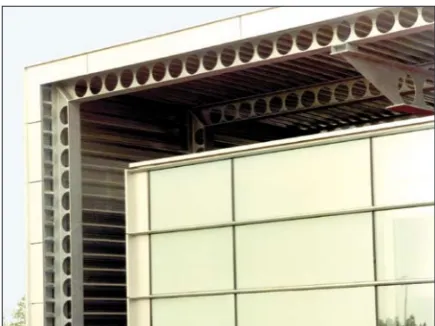
The design of building structures with a relatively vast useable area such as halls, store-rooms and plants is predominantly based on the use of openwork beams to ensure the required strength and load capacity. One example of pop-ular design solutions based on the use of open-work beams as load-carrying structures is shown
in the below figure.
Openwork I-section beams ensure higher operational conditions due to their reduced
sitivity to very high loads resulting from specif-ic weight and the impact of external loads. The popular methods for increasing load capacity of a structure often involve increasing the structure’s
specific weight due to the implemented design modifications. Nowadays, there is a demand for design solutions that ensure that a profile’s weight
is either similar to or – preferably – lower than the
original one, and that the profile has holes with a geometry affecting the concentration of stresses
and increasing its operational properties.
The problems of stability, critical and post-critical behavior have long been investigated by experts on load capacity and strength of
thin-walled profiles [2, 5, 8, 10, 16, 17, 20]. The prob -lems of stability loss and post-critical behavior of thin-walled elements with holes have been described in the publications [6, 19]. Axial com-pression is a common problem in everyday opera-tion of building structures with vast usable areas.
The problem of strength of profiles exposed to
axial compression becomes more serious during heavy snowfall, as snow tends to remain on the roof of a structure for a long time. It is therefore vital to make sure that carrying structures such
as the tested openwork I-section profiles exhibit
higher strength properties because, apart from supporting a considerable part of a structure’s weight, they are additionally exposed to unfavor-able weather conditions in winter. Modern design solutions such as holes described by hexagonal or – more recently – sinusoidal geometry have a
positive effect on decreasing the concentration of
stresses in crucial areas. Given the demand for solutions ensuring higher operational properties
of structures, it is justified to scrutinize both thin-walled profiles characterized by high load-carry -ing capacities and carried critical loads.
This paper presents a numerical analysis of buckling, stress and displacement, as well as
post-buckling states of openwork profiles with varying
lengths and hole diameters.
RESEARCH OBJECT AND METHODOLOGY
The research was made for thin-walled
I-sec-tion profiles with varying length and hole diame -ters with a constant cross section. The tested struc-tures have been assigned the properties of con-structional steel HISTAR® 460 characterized by
high strength, high hardness at low temperatures and excellent weldability. This innovative grade of steel has recently become popular in building industry, which provides new design opportuni-ties for the building and engineering industries.
I-section profiles made of the modern steel grade
and produced by hot rolling enable erecting in-novative and competitive building structures. The material properties of the discussed low-alloy steel with higher properties are listed in a table which is given below [16].
The numerical model was designed using ABAQUS®. The object was modeled as a shell
el-ement with a nominal thickness of 1 mm (the
visu-alization of the profile thickness was disabled dur
-ing the model-ing to enable further definition of the
numerical problem based on the problem of
non-linear statics). The defined thickness of the shell
element served for examination of the buckling of
a sample profile in order to visualize the model’s behavior under the defined loads. The I-section profile had normalized cross sectional dimensions
[24]. In all investigated cases, the cross sections were constant. The variables solely included the diameters of the holes made in the top plate of the
I-section profile. The hole diameters were changed
in a range from 30 mm to 50 mm, at every 10 mm.
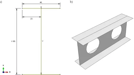
The height of the profile’s cross section was set
to 80 mm, while the length of the lower and
up-per plates was fixed to 46 mm. The simulations
Fig. 1. Example of application for openwork beams
Table 1. Material properties of steel HISTAR® 460
Histar® 460 Steel
Property Unit Value
Young modulus [E] MPa 210000
Poisson’s ratio [v] - 0.3
Yield point [Re] MPa 460
Yield strength [Rm] MPa 540
were performed for three cases of hole diameter variations. The ratio of diameter variations ranged between 37.5% and 62.5% relative to the constant
height of the vertical profile plate. The distance
between the centers of the holes was set to 100 mm. The cross section of the structure and the 3D model of an openwork beam with holes are shown
in the figure below.
The expected result of the first stage of the analysis was to obtain the first buckling mode under the defined unit load. The expected buck -ling mode can be produced after the application of load equal to the critical load which causes a
specific form of deformation in the model. Higher
buckling modes are possible due to model
inaccu-racies, definition of varying boundary conditions, or the occurrence of preliminary deflection.
The objective of the FEM analysis was to obtain
the first buckling mode applying the ideal geometry
of the model and boundary conditions. The possi-bility of shaping elastic properties of structures (via changing the geometry of holes in the model) is vi-tal in terms of correct operation of objects,
particu-larly when the application of openwork profiles de
-pends on a specific purpose. Due to high displace -ments and loads, the analysis examined the
numeri-cal model’s nonlinearity by the Newton-Raphson
method, an iterative algorithm for determination of approximate values of elements of functions de-scribing a given problem [1, 2].
The scope of the numerical computations was initially connected with the phenomenon of buckling as a part of nonlinear disturbance occurring in the process. The analysis involved
obtaining visualization of the first initial buck -ling modes of the tested element depending on its length. The obtained buckling mode was considered in further computations related to the investigation of the post-critical state (due to the highest probability of obtaining this mode). The boundary conditions of FEM models were
defined by articulated mounting in the upper and lower parts of the profile edges. Despite the three different lengths of the numerical models,
the boundary conditions were identical, and the degrees of freedom were blocked to ensure correct modeling of the structure’s behavior at buckling. The displacement due to load of the upper edges of the structure was uniform over the entire length of the model with a gradual
in-crease in the defined unit load. The figure below shows the defined boundary conditions and the unit load for the FEM model of a profile with a
length of 200 mm.
To maintain proper elasticity of the element, the numerical computations were performed only until the moment when the metal exceeded its yield stress at Re=460 MPa. The load of the
model shown in the above figure was applied evenly to all upper edges of the profile. A solu
-Fig. 2. Numerical model: a) cross sectional geometry of the profile, b) 3D object with a length of 200 mm and
with holes with a diameter of 50 mm
tion of the problem of the model’s behavior at
critical state involved a precise definition of dis
-cretization of the numerical element. The dis
-cretization of the model was performed using
four-node reduced integration shell elements, S8R, each having six degrees of freedom at every node. The discussed case involved
com-puting a shape function of first-order finite el -ements. The technique of reduced integration involves removal of false modes of
deforma-tion that occur in computadeforma-tions of higher-order polynomials to yield correct averaged results of stresses and displacements in the nodes [23].
The figure given below shows the generated fi
-nite element mesh for the tested profiles with three different lengths.
The discretization led to obtaining 1846 fi
-nite elements for the shortest profile, 4800 fi-nite elements for the medium profile, and 9415 finite elements for the longest profile. Thereby pre -pared numerical models were used in a prelimi-nary FEM analysis to obtain the buckling mode of the critical state for all tested specimens. The next stage was to determine the critical load for the tested models, for all cases of hole diameter
variations. The final stage involved an analysis
of the post-critical state including the geometri-cal imperfections caused by buckling. This stage involved the examination of displacements and stresses with respect to the critical loads deter-mined as a result of the structure’s buckling.
RESULTS
Based on the correctly defined problems of the buckling process, we determined the first modes of the critical state in the loaded profiles
with a length of 200, 500 and 1000 mm,
respec-Fig. 3. Boundary conditions of the numerical model
Fig. 4. Discrete model: a) profile with a length of 200 mm, b) profile with a length of 500 mm, c) profile with a length of 1000 mm
b)
tively, and with 50 mm diameter holes spaced at regular intervals.
The FEM analysis was performed based on
the first buckling mode, as this mode is the most
likely to be produced due to the ideal boundary conditions and the model’s geometry. The results demonstrate that the buckling mode (deformation in the form of half-waves) is the same despite the varying heights of the structures. The half-waves are located within the holes of the openwork beams. Additionally, it has been found that the critical load can amount to nearly 100%, despite the varying lengths of the thin-walled I-section structures. The results demonstrate that the length
of the profiles has no significant effect on the car -ried critical loads. The range of the car-ried
criti-cal loads for all profiles is between 26 210 N and 26 257 N. Below we present the results of critical loads for the shortest profile (200 mm) obtained at
varying diameters of the holes.
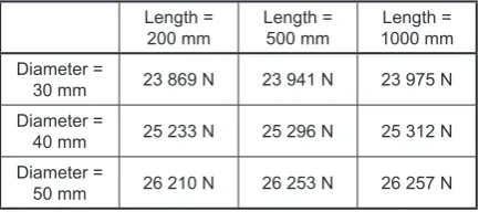
The next stage of the analysis involved
de-termination of the effect of varying the hole di -ameters in a range from 30 mm to 50 mm on the carried critical loads for the other lengths. The re-sults are listed in a table as the obtained values of
the critical loads versus profile lengths and hole
diameters.
The results demonstrate that the increasing
of the diameter of the hole has a significant ef -fect on the capacity of carrying higher critical loads. In addition, it is also observed that
pro-file length does not have any significant effect
on the load results. Given the binding standards and the applied structure design, the maximum diameter of holes should not be higher than 80% of the total height of the beam, while the dis-tance between them can be reduced to the
mini-mum [25]. The profile with a length of 200 mm
and 30 mm diameter holes has a critical load of
23 869 N, while for the profile with a length of
200 mm and a hole diameter of 50 mm the load
increases to 26 210 N, which is by about 10%.
Fig. 5. Visualization of the first buckling mode: a) profile with a length of 200 mm, b) profile
with a length of 500 mm, c) profile
with a length of 1000 mm
Table 2. Critical loads versus profile length and hole
diameter
Length =
200 mm Length = 500 mm 1000 mmLength = Diameter =
30 mm 23 869 N 23 941 N 23 975 N Diameter =
40 mm 25 233 N 25 296 N 25 312 N Diameter =
50 mm 26 210 N 26 253 N 26 257 N
a)
b)
The key advantage of applying larger diameter
holes in openwork profiles is that it entails re
-duced material volume and specific weight along with higher load capacity. The final stage of the
FEM analysis was to produce results describing the post-critical behavior of the structure. The investigation of the post-critical state also in-volved examination of the post-critical
equilibri-um paths of the profiles. The results of loads and
displacements enable determination of rigidity or energy consumption of the structures. The
re-lationships describing profile deflection due to
Z-axis compression and increase in load versus
deflection help describe the behavior of these
structures under load until their yield point. The diagrams given below illustrate the post-critical equilibrium paths which occur at the desired length and varying diameters of the holes.
The results of the post-critical equilibrium
paths describe the behavior of the profiles un -der the applied loads in accordance with the data given in Table 2. The compressive displacement along the Z-axis increases proportionally to the
applied load for the profiles with three different lengths. The profiles with 30 mm diameter holes are more rigid than the profiles with 50 mm di -ameter holes, with the latter being more energy-consuming. Depending on a demand, rigidity or energy-consumption of structures can be
in-creased. The elastic work of the profiles, which
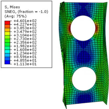
is particularly desired for purposes of the build-ing industry, does not exceed the yield point of the tested material. The highest concentration of stresses is spread symmetrically on the edges of
the holes in each tested type of profile. The figure
below illustrates the crucial spots of a 200 mm
long profile with a 50 mm hole diameter after
exceeding the yield point.
CONCLUSIONS
The paper presented the problem of
nonlin-ear stability of I-section profiles subjected to
axial compression. The numerical results reveal that there are similarities regarding the critical and post-critical behavior of the structures. The FEM analysis results helped determine the
ef-fect of variations in the diameter of the profile
holes on the critical loads of the models
depend-ing on the applied profile height. The essence of
this study was to determine the impact of height
of the thin-walled I-section steel profiles on the
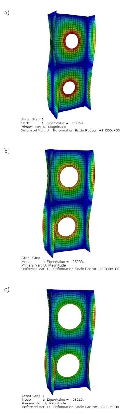
Fig. 6. Buckling mode and values of critical loads:
a) 23869 N, b) 25233 N, c) 26210 N
a)
b)
carried values of critical loads, as well as the im-pact of the variations in diameter of the holes
on load capacity of the profiles. The operational
reliability of thwalled structures can be in-creased thanks to adjusting the diameter of the holes, depending on whether we wish to produce
profiles with higher rigidity or profiles that ab -sorb energy generated by loads. The results led to the formulation of the following conclusions:
• height of thin-walled I-section profiles does not have a significant effect on the magnitude
of critical loads,
• increase in diameter of the holes in openwork beams leads to a desired increase in the mag-nitude of carried critical loads,
• the buckling mode obtained in the tests has the
same form of deformation for all profiles with
varying heights,
• post-critical equilibrium paths of the tested structures are similar for all models despite
varying heights of the profiles,
• maximum stresses described by a yield point Re = 460 MPa are concentrated near the edges of the holes,
• increase in diameter of the holes in the profiles
changes the place of concentration of the high-est strains.
The FEM results demonstrate vast opportu-nities for observation and thorough examination of deformation, as well as determination of cor-rect operational parameters of thin-walled
pro-files for a full range of load. Numerical analysis
is a powerful tool for investigating the load
ca-pacity and effort of thin-walled structures under defined loads.
Fig. 7. Post-critical equilibrium paths versus hole diameter
REFERENCES
1. Abaqus HTML Documentation.
2. Dębski H. Experimental investigation post-buck -ling behaviour of composite column with top-hat
cross section. Eksploatacja i Niezawodnosc –
Maintenance and Reliability, 2, 2013, 106–110. 3. Dębski H, Koszałka G, Ferdynus M. Application
of fem in the analysis of the structure of a trailer supporting frame with variable operation
param-eters. Eksploatacja i Niezawodnosc – Maintenance
and Reliability, 14 (2), 2012, 107–114.
4. Dębski H., Rudawska A. Experimental and nu -merical analysis of adhesively bonded aluminium
alloy sheets joints. Eksploatacja i Niezawodnosc –
Maintenance and Reliability, 1, 2011, 4–10. 5. Dębski H., Teter A., Kubiak T., Samborski S. Local
buckling, post-buckling and collapse of thin-walled channel section composite columns subjected to quasi-static compression. Composite Structures, 136, 2016, 593–601.
6. Falkowicz K., Ferdynus M., Dębski H. Numerical
analysis of compressed plates with a cut-out oper-ating in the geometrically nonlinear range.
Eksp-loatacja i Niezawodność – Maintenance and Reli -ability, 17 (2), 2015, 222–227.
7. Ferdynus M. An energy absorber in the form of a thin-walled column with square cross-section and
dimples. Eksploatacja i Niezawodność – Mainte -nance and Reliability, 15 (3), 2013, 253–258. 8. Koiter W.T. Elastic stability and post-buckling be
-havior. In: Proceedings of the Symposium on Non-linear Problems. Wisconsin: Univ. of Wisconsin
Press, 1963, 257–275.
9. Kołakowski Z., Teter A. Load carrying capacity of
functionally graded columns with open cross-sec-tions under static compression. Composite Struc-tures, 129, 2015, 1–7.
10. Kopecki T., Mazurek P. Problems of numerical bi -furcation reproducing in postcritical deformation states of aircraft structures. Journal of Theoretical and Applied Mechanics, 51 (4), 2013, 969–977. 11. Królak M. and Mania R.J., (eds.), Statics, dynam
-ics and stability of structures. Stability of thin-walled plate structures. Series of monographs.
Łodz: Technical University of Lodz, 2011.
12. Lonkwic P.: Influence of friction drive lift gears
construction on the length of braking distance. Chinese Journal of Mechanical Engineering, 28 (2), 2015, 363–368.
13. Lonkwic P., Różyło P.: Theoretical and experimen -tal analysis of loading impact from the progressive gear on the lift braking distance with the use of the free fall method. Advances in Science and Tech-nology Research Journal, 10(30), 2016, 103–109. 14. Lonkwic P., Różyło P., Dębski H. Numerical and
experimental analysis of the progressive gear body
with the use of finite-element method. Eksploatac
-ja i Niezawodność – Maintenance and Reliability,
17 (4), 2015, 544–550.
15. Mania R.J., Kołakowski Z., Bienias J., Jakubczak P., Majerski K. Comparative study of FML profiles
buckling and post-buckling behavior under axial loading. Composite Structures, 134, 2015, 216–225. 16. Material properties of steel, http://ds.arcelormittal.
com/repo/ArcelorMittal%20Staalhandel/Ru-briek%20Histar/Histar_EN.pdf.
17. Ritchie D., Rhodes J. Buckling and post-buckling behaviour of plates with holes. The Aeronautical Quarterly, 26 (4), 1975, 281–296.
18. Różyło P.: Optimization of I-section profile design by the finite element method. Advances in Science and
Technology Research Journal, 10 (29), 2016, 52–56. 19. Shanmugam N.E. Openings in Thin-walled Steel
Structures. Thin-Walled Structures, 28 (3/4), 1997,
355–372.
20. Teter A., Dębski H., Samborski S. On buckling col -lapse and failure analysis of thin-walled composite lipped-channel columns subjected to uniaxial
com-pression. Thin-Walled Structures, 85, 2014, 324–331.
21. Thompson J.M.T., Hunt G.W. General theory of elastic stability. New York: Wiley, 1973.
22. Van der Heijden A.M.A. (ed.), W.T. Koiter’s Elas -tic Stability of Solids and Structures. Cambridge University Press, 2009.
23. Zienkiewicz O.C., Taylor R.L. Finite Element
Method (5th Edition) Volume 2 – Solid Mechanics. Elsevier, 2000.
24. http://www.dziegielewski.info/Tablice/html/tabli
-ceipe.htm (dostęp: 25.11.2015).