INTRODUCTION
Numerical methods in optimising the con-struction become more and more popular. They are used both to save time and money instead of expensive construction prototyping. The publi-cations referring to the subject of modelling in different fields of science and technology can be found in literature. The results of experimental tests and numerical simulations for braking pro-cess of new CHP 2000 type progressive gear roller were presented in the publication [4]. A commercial packet is used as a numerical tool for calculations using Finite Element Method – ABAQUS program. The results of Finite El-ement Method simulation for C-shaped frame device to install the joints of sheet metal con-structions were presented by the authors of pub-lication [5]. In the analysis of the frame material effort a couple of versions of its geometry includ-ing the mass reduction were taken into account. For this purpose, the ABAQUS program was used by the authors. The program allows per-forming quantitative and qualitative assessment of the frame material effort. In publication [2] the results of numerical analysis for the semitrailer
frame construction of variable length and in-creased load capacity intended to transport over standard loads were presented by the authors. The research aimed at developing reliable FEM numerical models to identify the construction effort and deformation degree under the operat-ing loadoperat-ings conditions. In the publication [7] authors presented A quadrilateral element with smoothed curvatures for Mindlin-Reissner plates with the use of FEM method. The curvature at each point is obtained by a non-local approxima-tion via a smoothing funcapproxima-tion. The bending stiff-ness matrix is calculated by a boundary integral along the boundaries of the smoothing elements (smoothing cells). Numerical results showed that the proposed element is robust, computationally inexpensive and simultaneously very accurate as well as free of locking, even for very thin plates. The most promising feature of our elements is their insensitivity to mesh distortion. In addition to the above-mentioned areas of interest, the FEM method is used in the areas related to magnetism described in publication [6], vibration calcula-tions of various thin-walled structures [8] as well as modelling of liquids, air and thermal loads as well as beams and trusses simulations [10].
Optimisation of the Lift Carrying Frame Construction by Using Finite
Element Method
Paweł Lonkwic
11 The State School of Higher Education in Chełm, ul. Pocztowa 54, 22-100 Chełm, Poland e-mail: [email protected]
ABSTRACT
Numerical analysis of the carrying frame subassemblies strength installed in the friction lift was presented in this article. Two models of the frame loading were introduced. One of them was applied during loading and the other one during regular operation with nominal load capacity. Finite Element Method was used for calculations.
It allows mapping the actual operating conditions by using commercial SolidWorks software. Modifications in
the frame key subassemblies from geometrical point of view were proposed. Due to them, the frame weight was
reduced by 20% and a safety coefficient was maintained at the level of 3.
Keywords: FEM, a friction lift, simulation, modelling, Solid Works
Volume 12, Issue 4, December 2018, pages 207–215
https://doi.org/10.12913/22998624/100499
Research Journal
Accepted: 2018.11.05ings from 70-ties which are commonly called skyscrapers. Therefore, it is needed to optimise the structural elements from geometrical point of view and influence manufacturing and operating costs significantly.
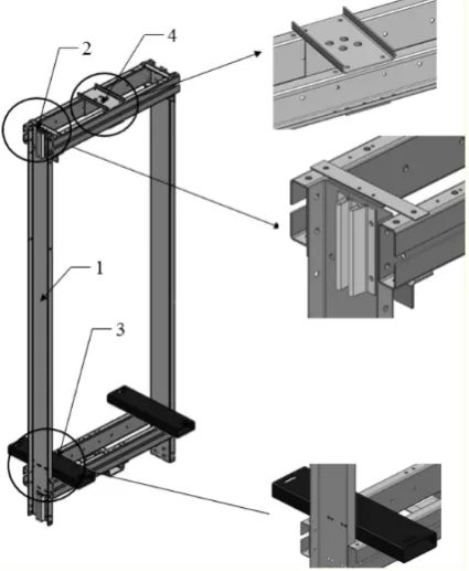
The carrying frame of the friction lift which was also a carrying subassembly of the cabin (3) was analysed and presented in Fig. 1.
The carrying frame has several key subas-semblies: the assembly of the lower beams, the assembly of the upper beams, the vertical beams that join the lower assembly with the upper one and the semi-platforms [11]. Both the assem-bly of the lower and the upper beams is made
the frame (1) to which the guide shoes (2) are in-stalled. The guide shoes move along the lift guides. In the upper assembly of the beams and in its cen-tral part there is a bracket (4), to which carrying lines are attached. The lift cabin rests on the beams of so called semi-platform (3) which is installed to the lower assembly of the beams – see Fig. 3.
The lift carrying frame consists of the ele-ments manufactured by bending and weaving technology. In this condition the frame is 132 kg. Optimisation of the frame construction for its mass with a safety coefficient of the construction maintained has a direct impact on two aspects:
• costs connected with the purchase of a device,
• rating power of the lift engine including the costs of operation.
The lift carrying frame is intended for the modernisation sector so the load capacity is 550 kg. It is connected with the number of persons that can travel in the cabin at the same time. The lift cabin mass varies from 375 to 405 kg, depend-ing on the equipment. Therefore, the lift carrydepend-ing frame in regular operation is loaded with 9550 N. The scheme of the lift frame loading can be di-vided into two stages. The applicable stages are present during the whole period of operation in an alternating way.
The scheme of the frame loading when pas-sengers get into the cabin – see Fig. 4a is recog-nised as the first scheme of loading. In this case, the force that loads the cabin step is assumed as the loading resulting from charging. The force value is calculated with the formula (1) [9]:
𝐹𝐹𝑠𝑠ൌ ͲǡͶ ∙ 𝑔𝑔 ∙ 𝑄𝑄 (1)
where: g – acceleration of gravity, 9.81 [m/s2];
Q – the lift rated load [kg]
Total loading of the carrying frame con-struction is assumed as a sum of loading cal-culated with the formula (1) and the loading resulting from the weight of an empty cabin [9] which is 2160 N.
The second scheme of loading is the effect of the lift operation. The frame is loaded with the maximum loading connected with its surface
area, Fig. 4b. In this case, the loading of the lift frame is the sum of masses resulting from a rated load and the mass of an empty cabin. The appli-cable loading is 9550 N.
With respect to the above, each present-ed scheme of the frame loading requirpresent-ed a separate analysis, individual conditions of mounting and the application of forces that load the frame construction.
The purpose and the scope of numerical analysis
The numerical analysis was performed to optimise the frame construction with respect to its mass and with the resistance of its component
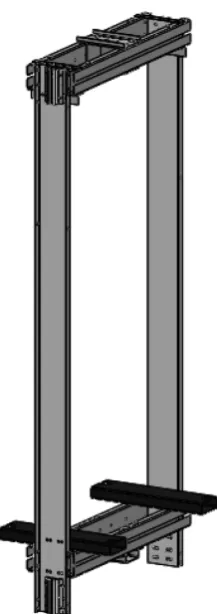
elements maintained. Geometrical model of the analysed object before optimisation (Fig. 5) was prepared in a form of the composition by using Solid Works CAD 2016 software, based on the drawing documentation.
The geometrical model of the carrying frame was the basis to develop a discrete model of the analysed object. This model was used to perform numerical calculations by using Finite Element Method. Geometrical model digitization was con-ducted by using volumetric finite elements of a global dimension of the mesh element 5 and with tolerance of 0.25.
For the purpose of optimising the carrying frame construction, the attention was paid to three component elements of the frame: trans-versal profiles located in the upper and the lower part of the frame and the semi-platform pro-files. A new shape of the frame transversal beam (Fig. 6a) with the thickness reduced by 3 mm and the semi-platform cross section profile (Fig. 6b) were proposed.
The optimised cross sections of structural elements of the carrying frame improved the frame unladen weight which was 105.4 kg. Thus, it was reduced by 26.6 kg, which consti-tutes 80% of the frame unladen weight before modifications introduced.
Linear and elastic characteristic for the mate-rial was used in numerical calculations due to the fact that there are no permanent deformations of the carrying frame component elements when the frame is operated. All component elements of the frame were made of steel with the following me-chanical properties :
• Young model E = 210 GPa,
• Poisson ratio ν = 0.3,
• Material density ρ = 7860 kg/m3,
• yield point Re = 230 MPa
Fig. 2. Crosswise dimensions of the frame carrying beam a) and the semi-platform b).
It was assumed that huge displacements can appear in the optimized model caused by the loading. That is why the concept can be nonlear from the geometrical point of view. The in-cremental and iteration Newton-Raphson method was used for the calculations [1, 3].
The results of numerical calculations
A numerical analysis was conducted for two design options of the carrying frame: be-fore and after modifications of the structure in two versions of the load. Detailed properties of
the carrying frame with FEM mesh applied are presented in Fig. 7.
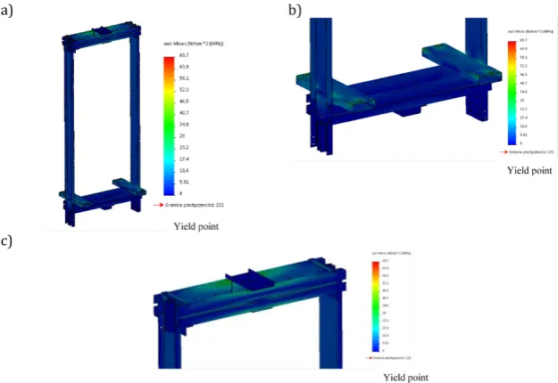
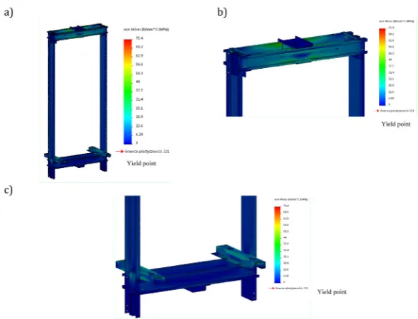
The results of numerical simulation for the stresses generated in the structural element of the frame in the second version of loading are present-ed in Fig. 8. In order to reflect the frame working conditions, the fixed mounting of the frame on the lines was used. The sliding mounting was used on the shoe guides. The loading of a total value of 9550 N was applied to four positions where the lift cabin presses together with the weight-carrying on the semi-platform profiles. The nu-merical analysis in the scope of stresses received in simulation proved that the semi-platform pro-files are the most critically stressed elements of the frame. The value of stresses generated in places where the loading is applied, approximates 70 Mpa. In the profiles located in the upper part of the frame, the generated stresses are close to the value of 55 MPa . The maximum stresses gener-ated in the structural elements of the frame are presented in Fig. 8.
The numerical analysis results for the 1st
version of loading are presented in Fig. 10 and Fig. 11. In order to reflect the frame operating conditions, the fixed mounting of the frame on the lines and on the shoe guides was used. The loading of a total value of 2160 N was applied in 2 places where the lift cabin threshold is pressed during the cabin loading.
Figure 12 presents the comparison of the obtained results for the stresses of the lift carrying frame elements before the profile op-timization due to the numerical analysis in two versions of loading.
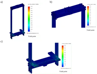
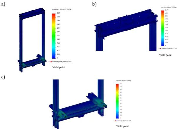
Analogous numerical simulation was con-ducted for the carrying frame with design modi-fications proposed the results of which are pre-sented in Figures 13, 14 and 15.
The values of stresses in respective as-semblies of the frame in relation to the loading scheme applied are presented in Fig. 16. Both,
Fig. 4. The loading scheme of the lift carrying frame: a) during loading, b) when operated.
in the first and in the second case, the values of stresses are below the values that are acceptable for the assumed material.
The simulation results show that depend-ing on the loaddepend-ing scheme the greatest effort is made by the upper assembly of the beams in the second scheme of loading. It is due to the fact that the frame is hung on the lines when the lift
is operated. Regardless of the loading scheme, the semi-platform profiles are the second most strenuous element of the frame. However, due to the values of stresses received for the respec-tive elements of the frame, the construction op-timisation was possible in terms of the profiles modification, maintaining a safety coefficient at least at the level of 3.
Fig. 6. Transversal dimensions of the frame carrying beam a) and semi-platform b).
Fig. 7. Discrete model of the carrying frame before design modifications:
a) the frame shoe guide, b) the carrying lines mounting, c) a semi-platfrom.
Fig. 8. The numerical analysis results for the lift carrying frame before the design optimisation:
Fig. 9. The numerical analysis results for the lift carrying frame before the construction optimisation in the scope of displacements: a) the frame model, b) semi-platform profile
Fig. 10. The numerical analysis results for the lift carrying frame before the construction optimisation: a) the
frame model, b) semi-platform profiles, c) the carrying lines mounting
Fig. 12. The values comparison of the stresses generated in the lift carrying frame subassemblies before design
modifications due to the loadings present in regular operation
Fig. 13. The numerical analysis results for the lift carrying frame stresses after the construction optimization with the 2nd scheme of loading: a) the frame model, b) the semi-platform profile, c) the carrying lines mounting
CONCLUSIONS
1. The method of modelling the carrying systems presented in this research paper by using Finite Element Method allows conducting the analy-sis of deformation degree and the level of car-rying elements effort under complex external loadings applied. The possibility to carry out the analysis at the stage of virtual prototyping is important when new design solutions are sought and when there are too many unknown design parameters while designing some com-plicated elements of machines and mecha-nisms. The knowledge on the stresses distribu-tion in the elements belonging to the carrying
system is a significant issue which allows eval-uating the adopted concept. A numerical analy-sis allows optimising the model parameters in order to design the most favourable solution to transmit specific operation loadings. The con-ducted analysis was used to evaluate the neces-sary modifications of design details to receive optimum solution.
2. The numerical calculations conducted with Fi-nite Element Method for the friction lift carry-ing frame proved that it is possible to reduce the frame mass at the expense of its resistance. 3. The carrying frame modification enabled to
reduce its mass by 20% and to maintain the construction stiffness and functionality. The
Fig. 15. The numerical analysis results for the lift carrying frame stresses after the construction optimization with the 1st scheme of loading: a) the frame model, b) semi-platform profile, c) the carrying lines mounting
Fig. 16. The comparison of the stresses values generated in the lift carrying frame subassemblies after design
presented modification is significant from the operational and economical point of view. 4. The prepared solid model of the friction lift
car-rying frame reflects the operating conditions of the structure under a fixed loading very well. The conducted analysis allowed evaluating the proposed design solution. It constitutes the ba-sis for implementing necessary manufacturing changes.
5. The proposed modifications for the frame channel bars profiles and the semi-platform profiles were introduced to production. They reduced the manufacturing costs and eventu-ally the final costs.
Acknowledgements
The research study was financed within coop-eration with LIFT POL company in the scope of the company development in the passenger lifts modernization market in Poland.
REFERENCES
1. Czmochowski J., Smolnicki T., Rusiński E.: Ad -vanced Finite Element Method in the support-ing structures. Of. Wydawnicza Politechniki
Wrocławskiej, Wrocław 2000.
2. Dębski H., Koszałka G., Ferdynus M.: Application
of FEM in the analysis of the structure of a trailer supporting frame with variable operation
param-eters. Eksploatacja i Niezawodność – Maintenance
and reliability 2012; 14 (2): 107–114.
3. Kacprzyk Z., Rakowski G.: Finite Element Method
in the structures mechanics. Of. Wydawnicza Po-litechniki Warszawskiej, Warszawa 2005.
4. Lonkwic P., Różyło P., Dębski H.: Numerical and
experimental analysis of the progressive gear body
with the use of finite-element method. Eksploatacja i Niezawodność–Maintenance and Reliability 2015; 17 (4): 544–550, http://dx.doi.org/10.17531/
ein.2015.4.9.
5. Markowski T., Mucha J., Witkowski W.: FEM analysis of clinching joint machine’s c-frame
rigid-ity. Eksploatacja i Niezawodność – Maintenance and reliability 2013; 15 (1): 51–57.
6. Meeker D.: Finite Element Method Magnetics. USA 2015
7. Nguyen-Xuan N., Rabczuk T., Stéphane B.,
Debongnie F. A smoothed finite element method
for plate analysis. Computer Methods in Applied
Mechanics and Engineering 2008; 197 (13–16),
https://doi.org/10.1016/j.cma.2007.10.008
8. Ping Zhua Z., Leiabc X., Liewab K., M.: Static
and free vibration analyses of carbon
nanotube-reinforced composite plates using finite ele
-ment method with first order shear deformation
plate theory. Composite Structures 2012; 94 (4), https://doi.org/10.1016/j.compstruct.2011.11.010 9. PN EN 81–20 Standard, Safety rules for the
con-struction and installation of lifts. Part 20: Passen-ger and goods-passenPassen-ger lifts, Warszawa 2017 10. Rao S. Singiresu: The Finite Element Method in
Engi-neering. Butterworth-Heiner of Elsevier, USA 2018 11. Szydło K., Longwic R.: Diagnostics of the passen -ger lift gear. Advances in Science and Technology
![Fig. 1. The cross section through the modernised lift shaft and the engine room [11].](https://thumb-us.123doks.com/thumbv2/123dok_us/8806006.1774590/2.595.107.248.377.742/fig-cross-section-modernised-lift-shaft-engine-room.webp)