INTRODUCTION
The comfort of a car is assessed in various ways, such as according to the softness of a seat, the type of the body, automatic or mechanical gearbox, electronic devices and so on. However, the key criteria for choosing a comfortable vehi-cle should be the absorption of the road inequali-ties, an intensity of the sensible vibrations and a perceptibility of the vehicle body oscillations.
Drivers or passengers of vehicles do not wish to feel any additional vibrations caused by the road irregularities. Comfort influences the psy -chological thinking of a person as well. If driving is comfortable, a person is calm and duly con-centrates their attention on driving the vehicle. Vibrations are the oscillations with amplitude that is considerably lesser than the geometrical parameters of the oscillating object. This physi-cal phenomenon may predetermine the mood and emotional outbursts of a person, so the influence
of the vehicle suspension characteristics on the driving comfort was assessed herein.
THE INFLUENCE OF SEMI-ACTIVE
SUSPENSION ON DRIVING COMFORT
The vehicle suspension reduces the influence of the road inequalities transferred to the vehicle body while driving on the roads of various lev-els of quality. Therefore, the shock absorbing and damping characteristics of suspensions should ensure safe and comfortable conditions for the transportation of passengers. While analysing the operation of a vehicle suspension, a certain assessment criterion that would define the qual -ity of the suspensions and enable comparing various versions, is required. Meanwhile, no uni-form parameter that would fully characterise the vehicle movement softness is accepted. The us-able assessment criteria include the displacement
Influence of Semi-Active Suspension Characteristics
on the Driving Comfort
Robertas Pečeliūnas
1*1 Vilnius Gediminas Technical University, Faculty of Transport Engineering, J. Basanavičiaus 28, 03224 Vilnius,
Lithuania
* Corresponding author’s e-mail: [email protected]
ABSTRACT
The article analyzes the influence of modern-day vehicle suspension characteristics on the passenger’s comfort
sensation. The cars with air suspension were selected for the experiments and the suspension was equipped with mode selection options – “Comfort” and “Sport” . A sinusoidal manoeuvre was ensured with a steering wheel rotation robot. The experimental tests were carried out by changing car suspension modes and wheel sizes. The experiments and data processing were carried out in accordance with the provisions of the ISO 2631–1 interna-tional standard. In the experimental test, the longitudinal and lateral acceleration projections captured by the sensor and roll rate of the vehicle were set to provide the most comfortable adjustment of the car suspension mode. After
filtering the measured vertical acceleration values, the comfort sensation was expressed as the root mean square (RMS) of vibration acceleration value. After evaluating the passenger’s sense of comfort, a summary of the effect
of the car suspension-driving mode was provided.
Keywords: driving comfort, semi-active suspension, steering wheel robot, root mean square, sinusoidal manoeuvre
Volume 14, Issue 1, March 2020, pages 18–25
https://doi.org/10.12913/22998624/113282
Research Journal
Accepted: 2020.02.04velocity, acceleration, body oscillations and so on. The problem of criterion choosing is intracta-ble because the task of describing the influence of vibrations on a human body by a single parameter is complicated [1, 9, 14, 16].
While describing the interaction between a human body and a source of vibrations, the sys-tem of coordinates ISO 2631–1 [5] with its origin in zone of the human heart was used. The direc-tions of the axes of coordinates conform to the stance of the person (Fig. 1). Establishing such a position of the point of origin of coordinates is rather difficult; in addition, provision of a precise description of the place where the oscillations should be measured is a complicated task as well. For a more precise analysis, the oscillations that
affect the main parts of the human body were as -sessed, i.e. individual points of origin of coordi-nates were established in the principal points be-tween the vibrating surface and the relevant part of the body. In such a case, the following points of origin of coordinates are foreseen for a sitting person: on the seat, in the point of the support of the feet and in the point of support of the back [4].
The problem of passengers’ comfort sensa -tion in modern vehicles was discussed upo by Dertimanis et al. In the study, the passive (Fig. 2) and active (Fig. 3) types of suspension systems as well as their influence on the travelling comfort were described [3].
In their studies, many researchers analysed: the response of the vehicle suspension to the road inequalities dependent on the vehicle wheelbase, the changes in the vehicle velocity dependent on the road surface, the passenger’s comfort sen -sation on different vibrations of the suspension caused by the road inequalities as well as different stiffness and dampness characteristics [2, 7, 11, 17]. The method accomplishing the test includes establishing the coefficients of displacement be -tween the rear axle and the front axle as well as the average values of the displacement between the rear axle and the front axle. Then, the road profiles (sinusoidal, highway or an urban street) are chosen. The coefficients of displacement be -tween the rear axle and the front axle as well as the averages of the coefficients of displacement between the rear axle and the front axle are insert-ed in the motion equation. According to the ob-tained displacements, the diagrams of oscillations Fig. 1. The system of coordinates usable for assessing
and accelerations are formed. The obtained re-sults were compared to the values presented in the provisions of the ISO 1520 standard [13].
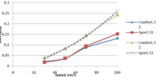
The ride comfort of a vehicle equipped with a semi-active suspension may be established ac-cording to the automatic suspension versions set-ting inside the vehicle. Žuraulis et al. carried out the tests on modern vehicles in “Comfort” and “Sport” suspension control modes. The benefit gained by the driver, when two different modes of driving are used, was analysed in the article. In the tests, two E class vehicles “Mercedes Benz” and “Opel Insignia” were involved. They are ve-hicles of quite different types. They were used for driving on two different 350 m long fragments of a motorway at different velocities: 30, 50, 70 and 100 km/h. During the experiment, the suspension settings were varied, whereas on movement with different velocities and on different road surfaces, the vertical acceleration in the zone of the pas-senger’s seat was fixed. For the test, a “Corrsys-Datron DAS-3” accelerometer, one of the key devices usable for travel comfort assessing, was used. In the course of varying the settings of the suspension and the whole chassis during the ex-periment, it was found that vibration affecting the passenger (the passenger’s vibration dose value) is lower at lower driving velocities (30 or 50 km/h). At higher velocities, the amplitudes of the vibrations increase; in the “Sport” mode, the amplitudes of vibrations were lower, as com-pared to “Comfort” mode. On movement upon
“Comfort” mode, the vehicle body was prone to vibrations of higher intensity [18, 19].
In the paper by Wang et al., the higher sup-port of the shock absorber (a mechanical element of a vehicle suspension), otherwise referred to as a shock damper, was analysed. The scientists had raised the question, whether a small detail in-tended to accept and mitigate the shocks from the shock absorber is able to influence the travelling comfort. The experiments were accomplished by driving on uneven roads, including protruding islands, corrugations and so on. During the ex-periment, it was proven to be important for the ride comfort, because a larger share of a shock absorbed by the shock absorber causes lower am-plitudes of the vibrations transferred to the body. While driving on protruding bumps, the absorb-ing materials of the relevant height and softness were chosen. Shock absorbers only move the body to the relevant direction; however, they do not transfer vibrations and oscillations to the driv-er’s and passengdriv-er’s seats [15].
In terms of braking and accelerating, the principle applicable for driving on bumps is ap-plied as well: on braking, the front shock damp-ers pull the shock absorber arm to the lower posi-tion, whereas while accelerating – the rear shock dampers press the shock absorber. The scientists tested this theory on several different models of vehicles; however, one negative factor had been observed: an attrition of shock dampers is much faster, because they are softer [10, 12, 15].
The key parameters of lateral dynamics include:
• lateral acceleration; • roll rate;
• body tilt angle in respect of longitudinal axis; • projection of the roll rate;
• projection of the pitch rate; • side-slip angle;
• yaw rate.
THE METHODOLOGY OF THE
EXPERIMENTAL RESEARCH
During the experimental research, a sinusoi-dal manoeuvre was carried out: the vehicle was moving with constant velocity of 40 km/h and its steering wheel was rotated at a certain angle on a certain moment. The type of the manoeuvre and the steering wheel rotating angle are shown in Fig. 4 below.
The conditions for an accomplishment of the experimental research:
• The vehicle under the research:“Mercedes Benz E” car.
• The equipment of the vehicle under the re-search is intended for measuring the vehicle body displacements and the accelerations in the lateral and vertical direction.
• Rotation of the vehicle steering wheel is con-trolled by the installed robot; the robot, in turn, is controlled via a controlling code pro-grammed by “Arduino” software.
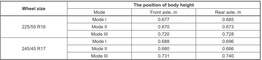
• The tests were carried while driving on asphalt pavement upon three different suspension control modes (the mode I – the minimum height of the body over the ground; the mode II – the middle height of the body over the ground; the mode III – the maximum height of the body over the ground (the measure-ment is performed between the road surface and the lowest point of the front and rear wing arc at the wheel centre) and different sizes of wheels: 225/55 R16 (hereinafter – 16ʺ) and 245/45 R17 (hereinafter – 17ʺ). The impact of different suspension modes on the distance be -tween the body and the road surface is shown in Table 1 below.
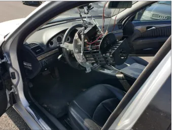
Upon striving to avoid considerable errors and those caused by the human factor during the ac-complishment of the manoeuvre, a rotating robot
Table 1. The distance of the vehicle from the road surface upon different suspension control mode
Wheel size Mode The position of body heightFront axle, m Rear axle, m
225/55 R16
Mode I 0.677 0.685
Mode II 0.670 0.673
Mode III 0.720 0.728
Mode I 0.688 0.696
had been fixed on the steering wheel (Fig. 5). The said robot is controlled by “Arduino” software where a programming code for the robot control-ling was developed.
The robot for the steering wheel rotation control is, in turn, controlled upon applying “Ar-duino” software. In the programming window, the key parameters of the sinusoidal movement foreseen for the experiment are shown: the rota-tion angle of the steering wheel – 80°, the time interval between its rotating actions – 1 second, the rate of the steering wheel rotatio – 2π/s, the reduction gear ratio – 3.64, the number of seg-ments of the manoeuvre – 5.
THE RESULTS OF THE EXPERIMENTAL
RESEARCH AND THEIR ANALYSIS
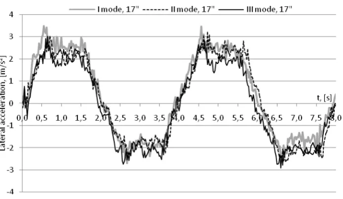
During the experiments, the total information obtained by the sensors was fixed; however, more attention was paid to observing the body tilt angle and the lateral acceleration. UIn order to establish the maximum values of the said parameters as well as their distribution and changes, the results of the experiments and their comparison were presented in diagrams (Figs. 6 and 7).
The summarised results of the experimental research are provided in Table 2 below.
Fig. 5. The robot for controlling the steering wheel turning used in the experimental research
The maximum lateral acceleration (3.67 m/s2)
was fixed for driving in mode I, with 16ʺ wheels, and the maximum body tilt angle (7.8º) was fixed for driving in mode II, with 16ʺ wheels. The min -imum lateral acceleration (3.02 m/s2) was fixed
for driving in mode III, with 17ʺ wheels and the minimum body tilt angle (6.05º) – for in II and 17ʺ wheels.
Root mean square (RMS) m/s2 shall be
calcu-lated as follows [6]:
( )
1 2 2
0
1T
w
RMS a t dt
T
æ ö
= ç ÷
è
ò
ø(1) where: T – duration of measurement (integration)
(s);
aw(t) – instantaneous weighted value of the vibration acceleration on the moment t in the direction of vertical axis (m/s2).
The weighted value of vibration acceleration aw(t) (m/s2) defines the different impact of fre
-quency on the response of human body to vibra-tion and is expressed as follows [8]:
( )
(
)
1 2 2
w n n
n
a t =æç W a× ö÷
è
å
ø (1)where: Wn – weighting factor applicable to the n-th frequency range;
an – the measured root mean square (RMS) of the vibration acceleration in the n-th frequency range (m/s2).
For a primary evaluation of a passenger’s comfort sensation, the methodology described in the ISO 2631–1 international standard [5] was chosen. According to the said methodology, the root mean square (RMS) was established. The calculations showed more considerable impact of the “Comfort” mode for speeds up to 50 km/h only. Higher differences between the values es -tablished for the “Comfort” and “Sport” modes were found for driving on asphalt pavement frag-ment with considerable road inequalities.
If the values of vertical accelerations caused by road inequalities are transferred from the time domain to the frequency domain, it becomes pos-sible to assess the amplitudes of the accelerations Fig. 7. Fluctuations of the lateral acceleration for different heights of the vehicle body
Table 2. Comparison of values of the lateral acceleration and the body tilt angle
Test Lateral acceleration, (m/s2)
Body tilt angle (in respect of longitudinal axis), (°) Maximum Average Maximum Average
Mode I, 16ʺ 3.67 2.88 6.48 4.42
Mode II, 16ʺ 3.36 2.51 7.68 4.53
Mode III, 16ʺ 3.24 2.34 7.12 5.01
affecting the passenger more objectively. At the minimum velocity, the “Sport” mode caused higher accelerations, as compared to the “Com-fort” mode; however, on increasing the velocity, the changes of the results were contrary. At higher velocities, higher limits of affected acceleration were achieved in the “Comfort” mode. This re-sult does not mean that the “Comfort” mode does not cause any additional sense of comfort. It was found that the maximum values of acceleration both in the “Sport” and “Comfort” mode take place at the frequency of 1.5 Hz, so it may be stated that the “Comfort” mode causes a higher sense of comfort, as compared to the “Sport” mode: the intensity of vibrations is the same, only the amplitudes are higher in the first case, i.e. in the “Comfort” mode.
CONCLUSIONS
• In the course of the experimental research, it was found that the maximum lateral acceler-ation of the vehicle is 3.67 m/s2 (on driving
upon the mode I with 16ʺ wheels), and the minimum lateral acceleration is 3.02 m/s2 (on
driving upon the mode III with 17ʺ wheels). The manufacturer points out that upon the latter suspension control mode, the velocity should not exceed 45 km/h, because the said mode is not applicable to higher velocities (they may cause too intensive vibrations of the body which, in turn, may reduce the grip of tyres on the road.
• While comparing the differences between the values of lateral acceleration of the vehicle body obtained in course of the experimental
research for different suspension modes, it was found that the maximum difference (21.5%) was fixed between the mode I with 16ʺ wheels and the mode III with 17ʺ wheels, and the minimum difference (1.5%) – between the mode III with 16ʺ wheels and the mode II with 17ʺ wheels.
• The difference between the maximum and minimum values of body tilt angle about the longitudinal axis found during the experimen-tal research was 1.63°, or 30%.
• While comparing the impact of the wheel size on the lateral acceleration of the body, it was found that the minimum impact was caused on driving in mode II with 16ʺ and 17ʺ wheels (2.1 %) and the maximum impact – on driving in mode III with 16ʺ and 17ʺ wheels (7.28 %). • Similar modern-day semi-active suspension
systems with different suspension-driving options show that even the “Comfort” mode can act as a sporty, stiff suspension in order to keep up with road irregularities and suppress the vertical occupant seat accelerations, hence maintaining optimal tire-road contact and en-suring traffic safety.
REFERENCES
1. Celko J., Decky M., Kovas M. An analysis of
ve-hicle – road surface interaction for classification of
IRI in the of Slovak PMS, Maintenance and Reli-ability, 1, 2009, 15–21.
2. Dąbrowski K., Ślaski G. Method and algorithm of
automatic estimation of road surface type for
vari-able damping control, Scientific Conference on Au -tomotive Vehicles and Combustion Engine, 2016, 1–10.
3. Dertimanis V.K., Chatzi E.N. LQR – UKF active comfort control of passenger vehicles with uncertain Dynamics. IFAC-PapersOnLine, 2018, 120–125. 4. Ikenaga S., Lewis F.L. Campos J. Active suspension
control of ground vehicle based on a full-vehicle model. Automation & Robotics Research Institute the University of Texas at Arlington, 2006.
5. ISO 2631–1:Mechanical Vibration and Shock – Evaluation of Human Exposure to Whole Body Vi-bration – Part International Organization for
Stan-dardization. Geneva, 1997.
6. Mansfield N. J. Human Response to Vibrations.
CRC Press, 2005.
7. Pikosz H., Ślaski G. Charakterystyki elementów sprężystych i tłumiących zawieszenia samocho
-du osobowego oraz zastępcze charakterystyki
ich modeli, Logistyka, systemy transportowe,
bezpieczeństwo w transporcie – LOGITRANS,
2010, 1–10.
8. Rimell A.N., Mansfield N.J. Design of digital filters
for frequency weightings required for risk assess-ments of workers exposed to vibration. Industrial
Health, 45, 2007, 512–519.
9. Sayers M.G.L., Tweddle A.L., Every J., Wiegand A.
Changes in drive phase lower limb kinematics dur-ing a 60 min cycldur-ing time trial. Journal of Science
and Medicine in Sport, 2012, 169–174.
10. Sande T.P.J., Besselink I.J.M., Nijmeijer H. Rule-based control of a semi-active suspension for mini-mal sprung mass acceleration: design and mea-surement. Vehicle System Dynamics, 54(3), 2016, 281–300.
11. Ślaski G. The influence of adaptive damping level
on vehicle vibration comfort–passenger car
ex-perimental tests results. Proc. of 7th International
Conference “Transbaltica 2011”, 2011, 200–205. 12. Sugai H., Buma S., Kanda R., Yoshioka K.,
Hasega-wa M. Preview Ride Comfort Control for Electric Active Suspension, Proceedings of the FISITA 2012 World Automo-tive Congress, Lecture Notes in
Electrical Engineering, 198, 2012, 147–161.
13. Tamboli D., Barter S., Jones R. On the growth of cracks from etch pits and the scatter associated with them under a miniTWIST spectrum. International Journal of Fatigue, 2018, 10–16.
14. Wang H.P., Ghazally I.Y.M., Tian Y. Model-free
fractional-order sliding mode control for an active vehicle suspension system. Advances in Engineer-ing Software, 115, 2018, 452–461.
15. Wang Y., Zhao W., Zhou G., Gao Q., Wang C. Sus -pension mechanical performance and vehicle ride comfort applying a novel jounce bumper based on
negative Poisson’s ratio structure. Advances in En
-gineering Software 122(October 2017), 2018, 1–12.
16. Wang W., Hou Z. Physical Parametric Model of an Automotive Electrohydraulic Semiactive Damper. IEEE Transactions on Vehicular Technology, 2019, 1–10.
17. Więckowski D., Dąbrowski K., Ślaski G. Adjustable
shock absorber characteris-tics testing and model-ling. In IOP Conf. Series: Materials Science and Engineering, 421, 2018, 1–10.
18. Žuraulis V., Pečeliūnas R., Jakutis G. Semi-active suspension influence on comfort sensation of ve -hicle occupant, 2014, 116–124.
![Fig. 1. The system of coordinates usable for assessing the vibrations that affect a human body [5]](https://thumb-us.123doks.com/thumbv2/123dok_us/8804513.1773827/2.595.138.462.542.753/fig-coordinates-usable-assessing-vibrations-affect-human-body.webp)
![Fig. 3. A kinematic model of an active suspension [3]](https://thumb-us.123doks.com/thumbv2/123dok_us/8804513.1773827/3.595.130.463.72.292/fig-kinematic-model-active-suspension.webp)