ORIGINAL ARTICLE
Personalization for Massive Product
Innovation Using Open Architecture
Qing‑Jin Peng
1,2*, Yun‑Hui Liu
1, Jian Zhang
2and Pei‑Hua Gu
2Abstract
Product innovation is creation of new concepts to plan and realize technological and functional details in the product to satisfy market and customer needs. One of the key drivers to product innovation is reactions of the product to users’ needs. Product innovation needs a cognitive design method based on needs of variant users for the product personalization. In this paper, an open concept is introduced to provide ways to meet user’s individual need in prod‑ uct lifespan. It is for industries to propose product concepts based on open sources, develop and support the product on the public capability. Using the open concept in the product architecture, called open‑architecture product (OAP), can improve the product personalization leading to massive product innovation. To promote this promise of the OAP, effective methods are discussed for the OAP development. This paper introduces research on OAPs using adaptable design methods to meet product personalization. Adaptable design is based on the modular structure for product adaptability using function modules and adaptable interfaces. The proposed method provides solutions for planning modules and implementation of OAPs. Methods of OAP module planning, detail and interface design are described for transformation of product concepts into physical structures. A multiple‑purpose electrical car is developed in a case study to show effectiveness of the proposed method.
Keywords: Product design, Personalization, Massive innovation, Open architecture, Adaptable design
© The Author(s) 2018. This article is distributed under the terms of the Creative Commons Attribution 4.0 International License (http://creativecommons.org/licenses/by/4.0/), which permits unrestricted use, distribution, and reproduction in any medium, provided you give appropriate credit to the original author(s) and the source, provide a link to the Creative Commons license, and indicate if changes were made.
1 Introduction
Product can be defined as a technical system satisfying specific needs [1]. Product innovation is the creation of new concepts in product design and manufacture. The potential of product innovation is from the creativity in design [2]. Despite the known importance of innovative design, there is a lack of effective approaches to creative design activities for the product innovation [3]. Brem et al. analyzed more than 2.6 million patents filed from 1978 to 2013 and found that the innovation is negatively influenced by dominant design methods in industry [4].
Integrating problem analysis and idea generation into product design can lead to the product innovation [2]. Product innovation is a process for planning and realiz-ing new technological details with necessary functions to satisfy users’ needs [1]. One of the key drivers to product
innovation is the interaction between the way of users to use the product and the way of designers to respond to the users [5]. As there is a verity of users with differ-ent needs for a product, personalization becomes an emerging trend in the product development. Innovation needs an effective and cognitive design method for prod-uct personalization based on user requirements [6]. The best practice to know user’s needs is to involve the user in product design, manufacturing and maintenance pro-cesses [7]. It was found that the failure rate of new prod-uct development can be reduced between 20% and 96% by integrating users in the product development [8].
Design by users was proposed to open the maximum possible channel for the users to involve in product design to specify their own needs to increase satisfactions [9]. Open innovation is a direction of the user involvement in product development [3]. Open concept provides ways to involve users in massive product innovation. The innova-tion should be the work done not only by product design-ers and manufacturdesign-ers, but also by usdesign-ers. The massive innovation, therefore, has to be open to public, or called
Open Access
*Correspondence: [email protected]
1 Department of Mechanical Engineering, University of Manitoba,
Winnipeg, MB R3T 5V6, Canada
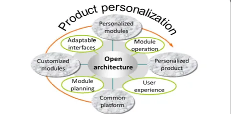
the open innovation. Open innovation is a relatively new concept. The basic premise of open innovation is opening up the innovation process, where an industry proposes product concepts based on open sources, and then devel-ops and supports the product on the public capability [3]. Open innovation requires the support from the prod-uct scheme or architecture to allocate the prodprod-uct func-tion to its physical components. Product architecture normally dominates the innovative process to form the product detail [1]. Therefore, the architecture approach provides a very important perspective for massive inno-vative research. Product architecture is an interactive pattern of functional modules in the product to form a technical system, which allows components of a product to interact and correlate with each other [1]. Therefore, using open concept in the product architecture, called open-architecture product (OAP), will form a bridge to link product developers and users for the massive inno-vation of products.
The OAP was proposed to provide a special manufac-turing mode to create flexible product structure using functional modules and adaptable interfaces [10]. Open-architecture products (OAPs) can support massive innovation by facilitating the involvement of users and third-party vendors in product development. The supe-riority of an OAP is to construct a personalized prod-uct to support particular functional needs with the ease of replacement of personalized modules in the original product [11]. This requires not only the modularization of products, but also the compatibility of product inter-faces and structures.
Adaptable design (AD) proposes a concept using the modular design to build products’ architecture for inter-actions of functional modules to meet user requirements [12]. AD meets function requirements using product lifecycle parameters. Product configurations, parameters and functions can be changed in the product lifespan to satisfy user changeable requirements [13]. A product design using AD is featured by the extendibility of func-tions, upgradeability of modules, and customizability of components [14].
OAPs can be designed using the AD method to imple-ment the modular structure. An OAP consists of three types of function modules including common platform modules made by manufacturers using the mass produc-tion, customized modules provided by manufacturers for customers choice, and personalized modules designed and supplied by customers or the third-party suppliers [15]. AD enables users to select different configurations in the OAP design stage, and to change product configu-rations in opeconfigu-rations with various options based on the need.
Different methods have also been discussed recently to meet change requirements in product design. These methods include a design change model based on ana-lyzing and searching change propagation paths [16], a synthesized multidisciplinary modeling method for understanding customer requirements [17], a math-ematical programming model to predict the change propagation impact [18], a grey rough model for fuzzi-ness and uncertainty of customer requirements [19], and a data driven uncertainty evaluation approach to support the design [20]. However, there is a lack of the general approach for designers to deal with the product person-alization in the product development.
In summary, the massive product innovation can be initiated by introducing the open concept to involve users in the product lifespan. Using OAP is a promise direc-tion of the massive product innovadirec-tion. Currently, there is a lack of research to provide effective methods for the OAP development. Following parts of the paper will first review the related research. Methods of the OAP devel-opment are then proposed as shown in Figure 1. Function module planning, design and interfaces will be discussed in detail. A multiple-purpose electrical car development is introduced to apply the proposed method.
2 Related Research 2.1 Product Structure
Product structure is the interactive pattern of physical components to implement product functions. Common product structures include integral structure and modu-lar structure. The integral structure is a single product block to implement function requirements. There is not a clear boundary of function components in the product. The demanded performance of an intended design can affect the choice of product structure [21, 22]. The inte-gral structure is often used for some key performance characteristics, such as the volume and efficiency related to the product size, shape and weight [23].
Design techniques of the integral structure are mainly for function sharing and geometric nesting. Function sharing integrates several parts or components into a
Personalized product
Common plaorm Module planning Adaptable
interfaces operaonModule
User experience Personalized
modules
Open architecture
Customized modules
single physical unit so that redundant physical parts and components can be eliminated to minimize the size and mass of a product [24]. Geometric nesting arranges the geometric profiles of components for the minimum volume with a desired shape. Function sharing and geo-metric nesting can help forming a highly compact design with the desired profile and interface. However, geomet-ric nesting inevitably incurs the interface coupling among components. It makes the integral structure hard to adjust for the function variety [22].
The modular structure breaks a product structure into discrete modules so that the product can fully function with interchangeable modules through well-defined interfaces [25]. The modular structure can increase product feasibility, variety, and durability by replacing, upgrading using add-on modules without affecting other parts of the product [15].
Therefore, the architecture, module and interface are three basic characteristics of the modular structure. The architecture is the combination pattern of modules. The module is an independent physical block correspond-ing to its function elements based on the physical and functional similarity. Modules are connected using a set of interfaces [26]. Miller and Elgard [27] defined that the difference between a simple block and a module is if they can realize a specific function. The interface is physi-cal connections between modules to achieve functional interactions [14], or a port that logically or physically integrates boundaries between systems or boundaries between systems and their environments [28].
Comparing with the integral structure, the modu-lar structure decreases function sharing, incurring the redundant physical expense, such as the interface, more parts and suboptimal use of the space, mass and energy. The performance based standardization also causes the excessive capability for each individual application. In short, the integral architecture gains the technical per-formance, and the modular architecture favours the busi-ness performance [22].
Most existing products use a somewhat hybrid struc-ture. Fixson and Park [29] used two dimensions of the function-component allocation and interface to measure difference between the integral and modular structure. Hölttä et al. [22] used Singular Value Modularity Index (SMI) to analyze the trade-off between the integral and modular architecture by analyzing three typical architec-tures including the fully integral, bus-modular, and fully modular. Their research shows that restrict technical constraints lead to a high degree of the integral structure, otherwise products tend to the modularization. Yin et al. [21] analyzed the cost and possible benefits from the integration of function modules by taking account of Sys-tem Integrator (SI) and Heavy SysSys-tem Integrator (HSI)
considering the product performance. They concluded three corollaries as 1) there is no single structure that is optimal in all cases, whereas there are always sub-optimal architectures; 2) for the global performance, the modular structure is a sub-optimal choice; 3) to obtain the global performance, the integral architecture is an optimal option. Open architecture has not been fully discussed to take advantages of the existing product structure in the development of mechanical products.
2.2 Adaptable Design
Adaptable design (AD) was proposed for product adapta-bility [12]. Axiomatic design has the similar consideration to deal with flexible requirements of different functions with corresponding design characteristics, where only a subset of functions with their physical characteristics is required at any time or circumstance so that the system has adaptability [30]. However, the AD does not mention how to form such systems. Current research shows that the product adaptability comes from the adaptable archi-tecture, modules and interfaces.
There are mainly four factors that influence product architecture, including the market variance, usage vari-ance, technology change and design method [31]. The architecture may relate to the task definition of a firm and industry structure. An interface of the product also affects the architecture [1]. The AD considers these fac-tors when forming the adaptable product.
Since the AD is based on the modular structure, the adaptable product architecture will follow a manner of the modular combination. Hölttä et al. [22] suggested two typical combination modes of modules depending on the spatial sequence and interface conditions. One is the fully modular where each module only connects to its direct neighbors; the other is the bus-modular where all modules are connected to a common platform. Two combination modes can grow and blend to form more complex modular combinations.
Specific to the AD, an important requirement is that when a module is adjusted, it only affects its ward sub-functions. With the architecture, any down-ward functional elements only interact with its updown-ward functional elements without affecting other parts of a product. Peng et al. [15] proposed an OAP using pub-lic interfaces to expand the product variety. The OAP is characterized as the common platform, customized modules and personalized components. Therefore, the OAP is essentially the modular structure. It emphasizes the product personalization.
personalization is also an effective way if the content for personalization is not enough to provide personalized offers [32]. An adaptable interface supports modules replaceable, upgradeable, and functionally variable abili-ties in OAPs.
Modules are connected through interfaces to form a modular product. The independence axiom of Axiomatic Design can guide the modularization of formed modules to be functional and physical uncoupled. In this aspect, Chen and Liu [1] used a concept of openness to evalu-ate the interface for the sharing level of resources. Their research shows that the standardization of interfaces can benefit products improvement. Interfaces are analyzed in terms of physical interface interaction factors to evaluate the general product adaptability. Hu et al. [26] proposed Interface Efficacy to evaluate the interface efficiency by integrating the interface graph representation, criteria matrix, and House of Quality.
2.3 Product Personalization
Product personalization can be measured based on dif-ferent factors. One factor considers the product adapt-ability for personalized needs as specific adaptadapt-ability and general adaptability. The specific adaptability is the product adaptability predicted under the design con-sideration. It can be evaluated by the comparison of the effort of product adaption with respect to the effort of new product creation [12]. Li et al. [14] evaluated the specific adaptability through the extendibility of func-tions, upgradeability of modules, and customizability of components. The extendibility of functions considers the potential function extension; upgradeability of modules considers the product improvement; and the customiza-bility of components considers the personal convenience of product adaption. Measurements of three aspects are then normalized and combined as the specific adaptabil-ity. The general adaptability is the product adaptability that is not considered initially. It is evaluated by compar-ing the actual or full architecture of a product with its ideal form of the segregated architecture, and quantita-tively measured based on characteristic parameters of interfaces and interactions.
Recently, Cheng et al. [33] defined the product adapt-ability for personalized needs using the essential adaptability and behaviour adaptability. The essential adaptability reflects the effort such as time, resource and energy to modify a current product for new func-tion requirements. An easy modificafunc-tion of funcfunc-tions will bring a good adaptability of the product. The behaviour adaptability reflects customers’ satisfactions of adapted products. It shows the cost-effective level of the adapta-tion activity. Their research is suitable to determine if an adaptation is proper for a product or not. An adaptation
should be implemented when both essential adaptability and behaviour adaptability are high. At three adaptable levels of the product, modules and parts for personal-ized needs, Peng proposed the design efficiency to eval-uate the implementation of adaptability considering three major factors of product architecture, complexity of interface, and operation ability [34]. Zhang et al. [35] applied the robustness to evaluate adaptability consider-ing adaptable activities that may happen at three levels: the parameter, configuration and architecture. For each level, methods were proposed to model design candi-dates and calculate the robustness so that an optimal design candidate can be identified with the best robust-ness. These research solutions have made a significant progress in the product personalization. But a general design method of the personalized product is overlooked.
In summary, a product can be designed using integral or modular structures. The integral structure uses func-tion sharing and geometric nesting to form highly com-pact products. Modular structure uses modules and interfaces to improve the product flexibility. Adaptable Design is based on the modular structure for product adaptability using the adaptable architecture, modules and interfaces. OAPs can effectively support the imple-mentation of product personalization. However, methods to form the open- architecture product including prod-uct module planning, forming and connection is still under research. Following parts of the paper introduce the proposed methods and applications for the design of personalized products.
3 Proposed Methods 3.1 Module Planning for OAPs
Module types of OAPs can be planned by the integration of extended quality function deployment (QFD) and axi-omatic design methods [36]. The degree of variety (DV) is expanded as a quantitative measure for various com-ponents to decide the difference of OAP function mod-ules. The weighted coefficient of variance index is used as a quantitative description of the variance measure to decide the module type. The index of weighted coeffi-cients of variances is used as a quantitative description of the variance measure as follows:
where i is a component number in the design matrix; VCi is the variance coefficient of technical requirements; (1) VCi=
n
j=1TCRj×ECj
,
(2)
rTIWi%=TIWi/
m
i=1TIWi×
100%,
(3)
TCRj is the correlation coefficient between the
cus-tomer requirement and technical requirement; ECj is
the expected requirement change; TIWi is the
techni-cal importance weight; rTIW is the relative importance of the average of technical requirements; wCOV is the weighted coefficient of variance.
The function variance is then decided by values of wCOVs for OAPs’ modules either meeting constant or variant function needs (FNs). The constant FNs form common platform modules. Variant FNs determine customized and personalized modules. Designers can specify FNs based on the function variant in product applications. DVi is used to assess components’
contribu-tions in different OAPs’ modules as follows:
Where xci is constant target values TVs; xvi is variant TVs; RW is the weight of technical requirements; Cqi is
rela-tionship values between components and FNs decided by TVs(C); lc are numbers of the total constant TVs (C); Cri is relationship values between components and FNs
decided by TVs(V); lv are numbers of the total variant TVs (V).
The design structure matrix (DSM) is finally formed to cluster product components to indicate degrees of the component variable. According to DVs, components are divided into three types of modules based on two thresh-olds of the variant. Threshthresh-olds are set based on variant FNs over constant FNs. From the assumption of need changes, different values of thresholds can be applied using manufacturers’ data and user requirement changes. Following relationships of components and their DV val-ues, components can be clustered into modules for an OAP.
3.2 Detail Design of the OAP
The detail design transforms module concepts into physi-cal structures of an OAP, which is conducted by convert-ing engineerconvert-ing recourses into physical utilizable formats. Mechanical components are designed to support energy/ force operations. For example, an electric vehicle can be driven by electrical power through energy/force opera-tions as shown in Figure 2.
Therefore, finding mechanical components for the energy/force action is critical in the OAP detail design. Therefore, a process is suggested in this research to transform the design concept into detailed mechanical
(4)
xci=
lc
q=1(RWq×Cqi), for constantTVs,
(5) xvi =
lv
r=1(RWr×Cri
), for variantTVs,
(6) DVi(%)=XVi/XCi×100(%).
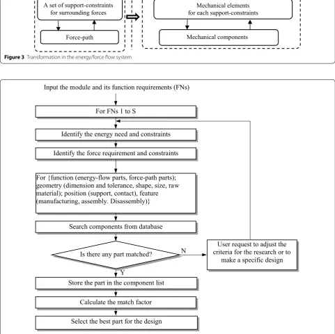
elements through the energy/force transforma-tion. Figure 3 shows the process of the energy/force transformation.
Design for the transformation first searches available components to meet function needs from the part data-base formed data-based on data in handbooks of engineering design. The component search uses criteria including functions to transfer energy and force; geometry to meet needs of the component shape, size, dimension and tol-erance, raw material; position to support and link other parts; features in manufacturing, assembly, and disas-sembly. The special design is considered only if there is no required component available to reduce manufactur-ing cost. A flow chart of the search process is shown in Figure 4.
Therefore, in the detail design, mechanical components are first searched based on the need transferring energy/ force to generate the power/motion required in the con-ceptual design. These components are then combined to form the function module. When integrating compo-nents together, limitations of materials and manufactur-ing methods may cause conflicts, such as the interference and un-matching. Two methods are applied to enable such combinations as follows:
(1) Each energy-force operation may have different mechanical components. It is possible to select a proper one so that all mechanical components can fit together. For example, a bearing seat can have dif-ferent profiles for difdif-ferent fixtures.
(2) Energy flows and force paths can be adjusted to enlarge the selection of mechanical components. For example, a straight tube can be bent to avoid a spatial interference.
In both situations, an initial structure is adjusted to best meet the overall solution of a product.
Electric motor (Electricity-rotation conversion)
Reducer (Rotation reduction)
Wheels (Rotations on the road) Electricity
Differential (Rotation distribution)
Car motion
Energy input Mechanical element to accept input energy
Energy output Mechanical element toprovide output energy
Mechanical components Energy-flow
Force-path A set of support-constraints
for surrounding forces for each support-constraintsMechanical elements
Mechanical components
Figure 3 Transformation in the energy/force flow system
Is there any part matched?
For {function (energy-flow parts, force-path parts); geometry (dimension and tolerance, shape, size, raw material); position (support, contact), feature (manufacturing, assembly. Disassembly)}
Search components from database Identify the energy need and constraints
Store the part in the component list
Calculate the match factor
Identify the force requirement and constraints
Select the best part for the design
N
Y For FNs 1 to S
Input the module and its function requirements (FNs)
User request to adjust the criteria for the research or to
make a specific design
3.3 Product Personalization
Product functions are normally processed as constant fac-tors in the product design. However, they can vary signifi-cantly for an OAP that will be adjusted by product users in the product lifespan. This requires multiple configura-tions of product funcconfigura-tions when customer’s requirement changes. As an OAP, some of its functions are commonly required, some are alternatively selected, and some are personalized options. These functions are met using com-mon, customized, and personalized functional modules connected by interfaces [11]. Therefore, following criteria are considered for OAPs to meet product personalization.
(1) Adaptability: customized and personalized function modules are designed to satisfy different require-ments of customers. The impact of customized and personalized functional modules on the common function modules should be reduced to the mini-mum.
(2) Openness: personalized function modules are designed to open to third-party vendors through open interfaces.
The personalization is the product change ability opened to the public to meet customers’ requirement changes. The product openness relies on the product interface efficiency [26]. Interface Efficacy (IE) is used as a measure based on key factors in interface design and operations. It evaluates the effectiveness of interfaces for connecting modules considering the product structure, interface connection and module handling in the opera-tion based on the design for assembly and disassembly. IE suggests that the interface should be designed simply in structure and easy in operation for the product function and reliability.
IE is proposed based on the geometrical and opera-tional complex of the connection operation for modules and interfaces. Criteria are measuring factors including interface connector attributes, such as the number, size, and weight; positioning attributes, such as the ease of position, and easy of handling; and operation attributes, such as accessibility, ease of assembly, tool applications. Geometry complexity includes parts’ size, shape and weight. Operation complexity considers fasteners’ opera-tion and posiopera-tion. Values of these elements are assigned by weighting factors for their importance in interface operations, including parts connected, connectors used, geometry complexity, operation complexity, tools used in the operation, and operation accessibility. For commonly used various fasteners, including bolt-nut-washer, screw, screw-washer, pin fit, taper fit, key-key way, and spline fit, their weighting factors are assigned considering the number of parts and tools used in the operation.
4 Case Study
A multiple-purpose electrical car (MEC) was developed for personalization using the proposed method in a case study. MEC is used by small businesses or families for commuting or shopping of a short distance transporta-tion. The user investigation found the need in different steering wheel options and trunks for different loads. MEC is designed as an OAP to meet a variety of user personalized requirements in the product lifespan. MEC development steps using the proposed method are as follows.
(1) MEC modules planning for the OAP based on cus-tomer requirements.
(2) Detailed modules and interfaces formation. (3) Design solutions for personalization.
4.1 Module Planning
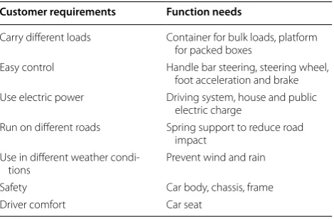
Customer requirements for MEC are collected from the user survey. The mapping from customer requirements (CRs) to product function needs (FNs) is summarized in Table 1.
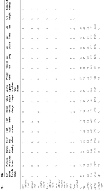
An extended QFD is built to plan MEC modules. The variant of customer requirements is identified based on MEC applications in the lifespan. Possible changes of the requirements are called expected changes or ECs that are in the last column of the matrix shown in Table 2 for the estimated values of user requirement changes. The extended QFD of MEC contains the current function needs (FNs) and future requirement changes (ECs). Using Eqs. (1)‒(3), the variance coefficient of technical require-ments (VC), the technical importance weight (TIW), rela-tive importance of technical importance weight (rTIW), and weighted coefficient of variances (wCOV) are calcu-lated as listed in Table 2 to plan function modules.
DV is decided using Eqs. (4)‒(6) to identify the variation of FNs. The greater the DV, the more likely the FN to perform
Table 1 Customer requirements (CRs) and product func-tion needs (FNs)
Customer requirements Function needs
Carry different loads Container for bulk loads, platform for packed boxes
Easy control Handle bar steering, steering wheel, foot acceleration and brake Use electric power Driving system, house and public
electric charge
Run on different roads Spring support to reduce road impact
Use in different weather condi‑
tions Prevent wind and rain
Safety Car body, chassis, frame
Table
2
Ex
tended QFD f
or
MEC modules planning
C or rela tion c oefficien t (Str
ong 6, M
edium 3,
W
eak 1, None 0 . Expec
ted changes of cust
omer need (high (H
=
3), medium (M
= 2), lo w (L = 1)) CRs
FNs Con
-tainer for
bulk loads Pla tf orm for pack ed b oxe s
Handle bar steering
St
eer
-ing wheel Foot acce
l-er
ation
Foot brak
e
House elec
tric
char
ge
Public elec
tric
char
ge
Spring suppor
t
to
reduc
e
road impac
t Pr ev en t wind Pr ev en t rain C
ar body
C
ar chassis
C
ar frame
C
ar seat CRs weigh
t
Expec
ted
change
Car
ry differ
ent loads 6 6 1 1 0 0 0 0 1 0 0 3 3 1 0 5 3 Easy con ‑ tr ol 0 0 6 6 6 6 1 1 0 1 1 0 0 0 0 5 1
Use elec
tr ic po w er 0 0 0 0 0 0 6 6 0 0 0 0 0 0 0 5 1
Run on diff
er ent roads 3 3 1 1 1 1 1 1 6 1 1 1 1 1 3 3 1
Use in diff
er ent w eather condi ‑ tions 3 3 1 1 1 1 1 1 1 6 6 1 1 1 1 3 3 Saf et y 1 1 3 3 1 1 3 3 1 3 3 3 3 6 3 5 1 Dr iv er comf or t 0 0 3 3 1 1 0 0 3 6 6 3 3 3 6 3 2 VC 31 31 22 22 13 13 14 14 19 35 35 22 22 19 21 TIW 53 53 65 65 44 44 56 56 40 59 59 45 45 50 45 rTIW (%) 6.8 6.8 8.3 8.3 5.6 5.6 7.2 7.2 5.1 7.6 7.6 5.8 5.8 6.4 5.8 w CO V 2.11 2.11 1.84 1.84 0.73 0.73 1.01 1.01 0.98 2.65 2.65 1.27 1.27 1.22 1.21 DV (%) 79.59 79.59 69.27 69.27 27.71 27.71 37.98 37.98 36.82 100 100 47.96 47.96 46.02 45.78 M
odule type
as a personalized module. The common platform is decided for FNs with less than 60% variation. Personalized modules are decided to conduct FNs with more than 70% variation. Customized modules are for FNs variations in between 60% and 70%. Therefore, seven modules are decided to build the MEC for different function requirements.
4.2 Detailed Modules Formation
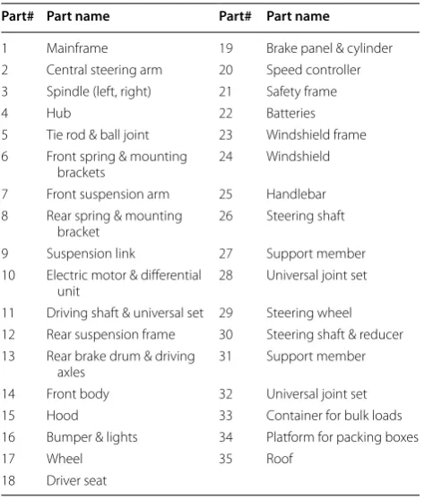
Using methods proposed in Section 3.2. The product conceptual modules are transferred into physical com-ponents. Thirty-five mechanical components are decided to form the physical structure of seven function modules based on search of mechanical components from the part database and common practice of the vehicle design, as shown in Table 3 and Figure 5. The relation of the com-ponents and modules are listed in Table 4.
Following discussion takes the common platform mod-ule as an example for the detail design. The modmod-ule per-forms functions of the steering, driving, chassis, body, safety frame and wheels. It is the most complicated struc-ture in the seven modules. The design develops the detail structure of the module using following search processes.
The steering system is an energy-flow system that can use a spline steering shaft for the input rotation. Wheel deflections are for steering. Other mechanical elements include ball joints and spindles. For the two motion link-ages and a rotation distribution, tie rods and a central
steering arm are applied to form the Ackerman steering geometry as illustrated in Figure 6(a).
The driving device is an energy-flow system that con-sists of batteries, a speed controller for foot acceleration, a brake panel unit for the foot brake, and two wheels to drive and brake as shown in Figure 6(b). An electric motor/differential unit is used for the electric-motion conversion and motion distribution.
The chassis is a force-path subsystem. By comparing different classic automotive structures for technical fea-sibility and cost, a chassis frame is designed using swing arm and leaf spring suspensions as shown in Figure 6(c). The combination of the steering subsystem with the chassis is shown as Figure 6(d) and 6(e). The chassis links the steering system using interface E. The rotation is per-formed by the steering shaft and bearings.
Combination of the driving system and chassis is shown in Figure 6(f) and 6(g). To avoid the transmission confliction between the fixed electric motor/differential unit and two vibrating wheels, straight rotation transmis-sions are adjusted as two-universal-joint transmistransmis-sions. Table 3 Physical Components
Part# Part name Part# Part name
1 Mainframe 19 Brake panel & cylinder
2 Central steering arm 20 Speed controller 3 Spindle (left, right) 21 Safety frame
4 Hub 22 Batteries
5 Tie rod & ball joint 23 Windshield frame 6 Front spring & mounting
brackets 24 Windshield
7 Front suspension arm 25 Handlebar 8 Rear spring & mounting
bracket 26 Steering shaft
9 Suspension link 27 Support member
10 Electric motor & differential
unit 28 Universal joint set
11 Driving shaft & universal set 29 Steering wheel 12 Rear suspension frame 30 Steering shaft & reducer 13 Rear brake drum & driving
axles 31 Support member
14 Front body 32 Universal joint set
15 Hood 33 Container for bulk loads
16 Bumper & lights 34 Platform for packing boxes
17 Wheel 35 Roof
18 Driver seat
Figure 5 Components of the MEC
Table 4 Components and Modules
Part# Module Type
1–22 1‑MEC platform Common
23–24 6‑Windshield Personalized
25–28 2‑Handlebar steering Customized
29–32 3‑Steering wheel steering Customized
33 4‑Container Personalized
34 5‑Loading platform Personalized
Two mounting brackets are used. The two-universal-joint transmissions are implemented using two driving shafts and universal joints. The electrical motor and differential unit are fixed on the chassis to transmit power to wheels.
These mechanical components are combined into a complete module, the chassis, to support steering and driving systems as shown in Figure 6(h). Figure 6(j) is the final formed platform module with added front body and seat units shown in Figure 6(i).
Finally, seven modules are formed for different MEC models to meet different user requirements. The com-mon platform module is required by all configurations of MEC models. Interfaces are required to connect the common platform module and other function modules. The attention is paid to the link between the common platform module and personalized modules that are to be easily replaced by users in the MEC application.
4.3 Interface Design
For bulk loads and packed boxes, interface A is designed considering the spatial need and loading weight as shown in Figure 7. Where Case A is for bulk loads, B is for packed boxes. For windshield and roof modules to pre-vent the airflow and rain drops, interfaces B, C and D are designed to connect them to the common platform mod-ule as shown in Figure 8. Interface E is used to connect two modules for the steering option.
Since modules’ functions are considered indepen-dently to meet requirements of the open architecture, these modules can be added or replaced by the user in the product lifespan. Considering the interface align-ment, fastening, interaction, and assembly/disassembly, mechanical structures of each interface are designed as follows:
(1) Interface A supports the loading weight from the container module for bulk loads, or the platform module for packed boxes. The preferred form is a set of flat planes with side profile constraints fastened to limit the six-degree freedom. This can also make the module a flat bottom to support loads.
(2) Interfaces B and C are used to connect the wind-shield module. Each of them adopts two fastening points so that total four fastening points to limit the six-degree freedom of the module.
(3) Interface D connects modules 3 and 7. The pre-ferred form is a set of flat planes with side profile constraints fastened to limit the six-degree free-dom.
Figure 6 Formation of the common platform module. a Acker‑
man steering geometry, b the driving device, c the chassis frame, d front view of the steering subsystem with the chassis, e side view of the steering subsystem with the chassis, f front view of the driving system and chassis, g side view of the driving system and chassis, h the complete chassis module, i front body and seat units, j the final formed platform module
Bulk loads
Interface A
Case A Box
loads
Interface A Case B
(4) Interface E is used to connect the roof module. The preferred form for connection/disconnection is a set of flat planes.
(5) Screws and nuts involved in the interfaces are same type and size so that all assembly/disassembly can be handled by users using a screw driver and wrench.
Therefore, the seven modules can be combined through interfaces to form more than ten different MEC models. Figure 9 shows these modules, and two models formed by the platform and selected customized and personal-ized modules.
5 Personalization Analysis
Product personalization results from advantages of OAPs to support variations of the product function. Per-sonalization applications are implemented by adding or replacing personalized modules in the product common platform. Therefore, the open architecture and inter-face commonality are important features of the product personalization. The architecture openness requires the allowance of a product to accept personalized function modules. Levels to meet this requirement are classified as follows:
(1) A product has enough space to add or replace a module without any obstacle. Users can handle the module adding and replacing easily.
(2) A product has space for a module, but the module adding or replacing will cause the disassembly of the product. Users can still handle module adding and replacing.
(3) There is not enough space in the product for the module, users cannot handle module adding and replacing.
The interface commonality shows the ability of an interface to connect different function modules, which is affected by its geometric shape and interactions. The sim-ple and standard interfaces are preferred. Levels to meet this requirement are as follows:
(1) An interface uses the connection or disconnection with a flat plane or stripe plane, or the standardized professional connection, such as hydraulic hoses and electric inserts.
(2) An interface uses a specialized connection or disconnection developed by manufacturers, or requires an connecting device such as a connector to connect two modules.
(3) There is no means to connect two modules.
These levels form criteria to evaluate the effectiveness of an OAP.
The architecture openness and interface commonality of the MEC are carefully implemented in the design pro-cess. The product personalization is ensured by following above suggested high levels of the architecture open-ness and interface commonality. Therefore, the designed MEC can form more than 10 different models by func-tion module combinafunc-tions to meet user personalizafunc-tion requirements. The future needs can be met by adding more personalized modules either provided by users or developed by the third-party industries.
MEC modules
1. Common platform 2. Handlebar (customized)
3. Steering wheel (customized) 4. Container (Personalized)
5. Rear Platform (Personalized) 6. Windshield (Personalized)
7. Roof (Personalized)
Different models can be formed based on customer needs, two examples are as follows.
Model A(Modules 1+3+4+6+7) Model B(Modules 1+2+5)
6 Conclusions and Remarks
Open architecture has the potential to support massive product innovation in following two aspects:
(1) As different users and industries can involve in product development, new designs can be devel-oped to satisfy various market segments, leading to massive innovation in product developments. (2) Product modules are developed with
technolo-gies from different sources that can be integrated through adaptable interfaces to lead massive inno-vations in technology integration. Therefore, the open architecture can address the challenge of mas-sive product innovation with following solutions.
• Better functionality: it allows product design to incorporate new technological advancements, • High quality: It utilizes the proven modules and
associated processes and knowledge,
• Lower costs: It reuses designs, common modules and components,
• Short delivery time: It reuses the existing design and manufacturing processes,
• Personalization: It uses personalized modules to meet change requirements,
• Environment friendly: It extends the product life and reduces wastes.
However, OAPs research is still in its early stage. As a concept, it is clear with certain advantages. As a method, although is incomplete, it had been used for various product development. As a theory, it needs the scientific foundation. Significant efforts are required to establish its theoretical foundation for a cost-effective method. In order to apply the open architecture to the product design in industry, a tool should be developed so that engineers can use it in the daily design work. We are working in this direction.
Authors’ Contributions
Q‑JP, JZ and P‑HG were in charge of the whole trial; Q‑JP wrote the manu‑ script; Y‑HL assisted with sampling and laboratory analyses. All authors read and approved the final manuscript.
Author details
1 Department of Mechanical Engineering, University of Manitoba, Winnipeg,
MB R3T 5V6, Canada. 2 Department of Mechatronics Engineering, Shantou
University, Shantou 515063, China.
Authors’ Information
Qing‑Jin Peng is a professor at Department of Mechanical Engineering at Uni-versity of Manitoba, Canada. He received his BSc and MSc Degrees from Xian Jiaotong University, China, and Doctorate from University of Birmingham, UK. His research interests are digital manufacturing systems, design for sustainability, system modeling and simulation. He is a visiting professor at Shantou Univer‑ sity. Tel: +1‑204‑4746843; E‑mail: [email protected].
Yun‑Hui Liu received his master’s degree from University of Manitoba, Canada. He has been extensively involved in new product development in dif‑ ferent industries including utility vehicles, tractors, furniture and manufacture equipment. He is currently a mechanical engineer at Scojet Inc., Brunswick, GA, USA. E‑mail: [email protected].
Jian Zhang is an associate professor at Shantou University, China. He received his PhD degree from University of Calgary, Canada. His research interests include adaptable design, interface design, and robust design. E‑mail: [email protected].
Pei‑Hua Gu is a professor at Department of Mechatronics Engineering at Shantou University, China. Professor Gu was the Head of Mechanical and Manufacturing Engineering and holder of NSERC Chair in Life Cycle Design Engineering at University of Calgary, Canada. He is Fellow of the Canadian Academy of Engineering and International Academy of Production Engineering (CIRP). His research interests include adaptable design, robust design, and CAD/CAM. E‑mail: [email protected].
Competing Interests
The authors declare that they have no competing interests.
Ethics Approval and Consent to Participate Not applicable.
Funding
Supported by Discovery Grants (Grant No. RGPIN‑2015‑04173) of the Natural Sciences and Engineering Research Council (NSERC) of Canada, and National Natural Science Foundation of China (Grant Nos. 51375287, 51505269).
Publisher’s Note
Springer Nature remains neutral with regard to jurisdictional claims in pub‑ lished maps and institutional affiliations.
Received: 26 June 2017 Accepted: 16 April 2018
References
1. K M Chen, R J Liu. Interface strategies in modular product innovation.
Technovation, 2005, 25: 771–782.
2. Y T Ko. Modeling a hybrid‑compact design matrix for new product inno‑ vation. Computers & Industrial Engineering, 2017, 107: 345–359. https://doi. org/10.1016/j.cie.2016.04.016.
3. E K R E Huizingh. Open innovation: State of the art and future perspec‑ tives. Technovation, 2011, 31: 2–9.
4. A Brem, P A Nylund, G Schuster. Innovation and de facto standardization: The influence of dominant design on innovative performance, radical innovation, and process innovation. Technovation, 2016, 50–51, 79–88. https://doi.org/10.1016/j.technovation.2015.11.002
5. M Orihata, C Watanabe. Evolutional dynamics of product innovation: the case of consumer electronics. Technovation, 2000, 20: 437–449. 6. F Zhou, Y Ji, R J Jiao. Affective and cognitive design for mass personaliza‑
tion: status and prospect. J. Intell. Manuf., 2013, 24: 1047–1069. 7. C Berry, H Wang, S J Hu. Product architecting for personalization. Journal
of Manufacturing Systems, 2013, 32: 404–411.
8. K Backhaus, J Jasper, K Westhoff, et al. Virtual reality based conjoint analysis for early customer integration in industrial product development.
Procedia CIRP, 2014, 25: 61–68.
9. K P Risdiyono. Design by customer: concept and applications. J. Intell. Manuf., 2013, 24: 295–311.
10. Y Koren, S J Hu, P Gu, et al. Open‑architecture products. CIRP Annals‑
Manufacturing Technology, 2013, 62(2): 719–729.
11. C Hu, Q Peng, P Gu. Adaptable interface design for open‑architecture products. Journal of Computer‑Aided Design and Applications, 2015, 12(2): 1–10.
13. D Xue, G Hua, V Mehrad, et al. Optimal adaptable design for creating the changeable product based on changeable requirements considering the whole product life‑cycle. Journal of Manufacturing Systems, 2012, 31: 59–68.
14. Y Li, D Xue, P Gu. Design for product adaptability. Concurrent Engineering: Research and Applications, 2008, 16(3): 221–232.
15. Q Peng, Y Liu, P Gu, et al. Development of an open‑architecture electric vehicle using adaptable design. Lecture Notes in Mechanical Engineering, Springer International Publishing, Switzerland, 2013: 79–90.
16. H Z Zhang, G F Ding, R Li, et al. Design change model for effective scheduling change propagation paths. Chin. J. Mech. Eng., 2017, 30(5): 1081–1090. https://doi.org/10.1007/s10033‑017‑0169‑2.
17. X J Ma, G F Ding, S F Qin, et al. Transforming multidisciplinary customer requirements to product design specifications. Chin. J. Mech. Eng., 2017, 30(5): 1069–1080. https://doi.org/10.1007/s10033‑017‑0181‑6. 18. S Ma, Z Jiang, W Liu, et al. Design property network‑based change
propagation prediction approach for mechanical product develop‑ ment. Chin. J. Mech. Eng., 2017, 30(3): 676–688. https://doi.org/10.1007/ s10033‑017‑0099‑z.
19. P Wang, Y Gong, H Xie, et al. Applying CBR to machine tool product configuration design oriented to customer requirements. Chin. J. Mech. Eng., 2017, 30(1): 60–76. https://doi.org/10.3901/cjme.2016.0113.007. 20. B Liu, S Huang, W Fan, et al. Data driven uncertainty evaluation for com‑
plex engineered system design. Chin. J. Mech. Eng., 2016, 29(5): 889–900. https://doi.org/10.3901/cjme.2016.0422.058.
21. Y Yin, I Kaku, C G Liu. Product architecture product development process system integrator and product global performance. Product Planning & Control, 2014, 25(3): 203–219.
22. K Hölttä, E S Suh, O Weck. Trade‑off between modularity and perfor‑ mance for engineering systems and products. International Conference on Engineering Design, ICED 05, Melbourne, August 15–18, 2005.
23. C C Huang. Overview of modular product development. Proc. Natl. Sci. Counc. ROC (A), 2000, 24(3): 149–165.
24. K Ulrich. The role of product architecture in the manufacture firm.
Research Policy, 1995, 24: 419–440.
25. T W Simpson, J Jiao, Z Siddique, K Hölttä‑Otto. Advances in product family and product platform design: Methods & applications. Springer, New York, 2013.
26. C Hu, Q Peng, P Gu. Interface adaptability for an industrial painting machine. Journal of Computer‑Aided Design and Applications, 2013, 11(2): 182–192.
27. T D Miller, P Eldard. Defining modules, modularity and modularization.
Design for Integration in Manufacturing, Proceedings of the 13th IPS Research Seminar, Fuglsoe 1998, ISBN 87‑89867‑60‑2.
28. R Keyvan, T Vincent. Ontology based interface design and control meth‑ odology for collaborative product development. Computer‑Aided Design, 2012, 44: 432–444.
29. S K Fixson, J K Park. The power of integrality: Linkages between product architecture innovation and industry structure. Research Policy, 2008, 37: 1296–1316.
30. N P Suh. Axiomatic design advances and applications. Oxford University Press, 2001.
31. J B Dahmus, J P Gonzalez‑Zugasti, K N Otto. Modular product architec‑ ture. Design Studies, 2001, 22(5): 409–424.
32. K Kwon, C Kim. How to design personalization in a context of customer retention: Who personalizes what and to what extent? Electronic Com-merce Research and Applications, 2012, 11: 101–116.
33. Q Cheng, G J Zhang, Z F Liu, et al. A structure‑based approach to evalu‑ ation product adaptability in adaptable design. Journal of Mechanical Science and Technology, 2011, 25(5): 1081–1094.
34. Q Peng, Y Liu, P Gu. Improvement of product adaptability by efficient module interactions. IDETC/CIE 2014, August 17‑20, 2014, Buffalo, New York, USA. DETC2014‑35183.
35. J Zhang, D Xue, P Gu. Adaptable design of open architecture products with robust performance. Journal of Engineering Design, 2015, 26(1‑3): 1–23.