O R I G I N A L A R T I C L E
Shape Error Analysis of Functional Surface Based
on Isogeometrical Approach
Pei YUAN1•Zhenyu LIU1•Jianrong TAN1
Received: 4 May 2016 / Revised: 14 February 2017 / Accepted: 2 April 2017 / Published online: 13 April 2017 The Author(s) 2017. This article is an open access publication
Abstract The construction of traditional finite element geometry (i.e., the meshing procedure) is time consuming and creates geometric errors. The drawbacks can be over-came by the Isogeometric Analysis (IGA), which integrates the computer aided design and structural analysis in a unified way. A new IGA beam element is developed by integrating the displacement field of the element, which is approximated by the NURBS basis, with the internal work formula of Euler-Bernoulli beam theory with the small deformation and elastic assumptions. Two cases of the strong coupling of IGA elements, ‘‘beam to beam’’ and ‘‘beam to shell’’, are also discussed. The maximum relative errors of the deformation in the three directions of can-tilever beam benchmark problem between analytical solu-tions and IGA solusolu-tions are less than 0.1%, which illustrate the good performance of the developed IGA beam element. In addition, the application of the developed IGA beam element in the Root Mean Square (RMS) error analysis of reflector antenna surface, which is a kind of typical func-tional surface whose precision is closely related to the product’s performance, indicates that no matter how coarse the discretization is, the IGA method is able to achieve the accurate solution with less degrees of freedom than stan-dard Finite Element Analysis (FEA). The proposed research provides an effective alternative to standard FEA for shape error analysis of functional surface.
Keywords RMS errorIsogeometric analysis Euler-Bernoulli beam
1 Introduction
Functional surface is a type of complex surface, which is ubiquity in mechanical and electrical equipment, realizes specific physical performances, such as electric, magnetic, optic and thermodynamic performance. The accuracy of functional surface, which is the critical function structure of a product, has a significant impact on the product’s performance. Antenna surface is a kind of typical func-tional surface, which realizes transmitting and receiving of electromagnetic signal. As in the case of reflector antenna where the reflector surface is such a functional surface, the influences on reflector surface precision from external loads, manufacturing and assembling errors [1–5] are considerable in changing the amplitude and phase dis-tribute of antenna aperture to affect the far electric field of antenna. And the surface root mean square (RMS) of half-path-length error is always adopted to estimate the gain degradation according to the Ruze equation [6]. In recent years, more and more large reflector antennas are equipped with shape control systems to estimate the surface errors. TANAKA [7] added intentional deformations on an antenna surface using the surface adjustment mechanisms to estimate the surface errors. And a dynamic shape control strategy of deployable mesh reflectors via feedback approaches was proposed by XIE, et al [8]. Other adjust-ment strategies have been investigated by several researchers [9–11]. In order to get the control inputs to actively adjust the surface shape, measurement methods and numerical simulations are adopted to estimate the surface error. The phase-retrieval holographic analysis Supported by National Natural Science Foundation of China (Grant
Nos. 51490663, 51475418, 51521064), and Zhejiang Provincal Key Development Program of China (Grant No. 2017C01045). & Zhenyu LIU
1 State Key Lab of CAD&CG, Zhejiang University,
[12, 13], photogrammetry measurements [14], etc. are widely used to measure shapes of reflector antennas. Although measurement methods could easily acquire the surface displacement distribution, the measure accuracies rely on the special equipment and the antenna’s wave-length. The numerical simulations, Finite Element Analy-sis(FEA), are good alternates in shape error analysis due to the advantage in optimization of the initial prototype designs. YOON [15] formulated a shape error minimiza-tion problem for a mechanically deformable reflector antenna structure in the frame work of the FEA. YOU, et al [16], used a 3-nodes laminated shell element based on Lagrange’s equations to study the characteristics of the reflector. DU, et al [17], employed the FEA to calculate the sensitivity matrix of the nodal displacement to deal with the worst-case optimization problem of cable mesh reflector antenna. However, only the displacements of the elements nodes can be applied to calculate the RMS error since the points in the element have inherent discretization errors which are especially bad for surfaces with a rela-tively coarse mesh. Refined mesh is required to improve the simulation accuracy, which would in turn makes the calculation more time consuming.
Isogeometric analysis (IGA) [18] is a method aimed at avoiding the discretization errors by using the same basis for analysis as is used to describe the geometry, thus enabling IGA to discretize the analysis models exactly. The necessary continuities between elements,C1continuity for Kirchhoff-Love element as an example, can be easily achieved by the high-order geometric basis functions. The method is now further developed in many areas including structural analysis [19–21], fluid-structure interaction [22], shape optimization [23, 24], topology optimization [25, 26], electromagnetic analysis [27], etc.. New IGA elements [28,29] are developed by researches. However, the non-interpolatory nature of the geometric basis func-tions makes the imposition of even the simple boundary conditions more difficult. Weak and strong methods are studied to the coupling [30–32] and boundary condition imposition issues [33,34] to perfect the novel method. The method is now capable to deal with the majority of engi-neering issues. The exact geometric discretization of IGA enables us to achieve more accurate solutions by much less degrees of freedom than that of traditional FEA.
The paper is organized as follows. In section2, a brief introduction of the surface error estimation is presented, include the relationship between the RMS half-path-length error and antenna gains, the normal deviation, etc. In sec-tion3, a rotation-free three-dimensional IGA beam ele-ment combined with Be´zier extraction is developed, and a Kirchhoff-Love shell element is also introduced in brief. Then the coupling of the two elements is presented. Moreover, at the end of the section, the RMS error is
written in the form of IGA. In section4, several examples are presented to verify the effectiveness of the developed beam element and its application in the RMS error analysis of antenna reflector. Finally, concluding remarks are given in section5.
2 Surface Error Estimation
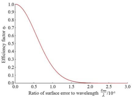
The impact of antenna surface errors on antenna gains can be derived from the Ruze equation [35], the reflector aperture efficiency is multiplied by an exponential factor
gs¼
G G0
¼exp 4perms k
2
" #
; ð1Þ
wheregsis an efficiency factor known as surface tolerance
efficiency,G0is the gain of the antenna in the absence of surface errors,Gis that of the deformed surface,ermsis the surface error, or RMS half-path-length error, k is the wavelength.
As shown in Fig.1, the efficiency factor decreases rapidly with the increase of the surface error, and the aperture efficiencygs=54.1% whenerms=k/16.
As a result, severe surface accuracy is demanded by the microwave antennas which work on the wavelength between 3 to 150 mm. The half-path-length errors are obtained from the geometrical deviations between the actual and ideal surfaces
ei¼
Di ffiffiffiffiffiffiffiffiffiffiffiffiffiffiffiffiffiffiffi
1þ ri 2f
2
r ; ð2Þ
where subscript i denotes the arbitrary pointi on the sur-face,ridenotes the radius ofith point on the reflector,fthe
focus length, and Diis the normal deviation:
Di¼
1 2 ffiffiffiffiffiffiffiffiffiffiffiffiffiffiffiffiffif fð þziÞ
p ½xiðuiuAÞ þyiðvivAÞþziðwiwAÞ
2hziyiuxðziþ2fÞ þxiuyðziþ2fÞ
¼Y uð i;vi;wiÞ;
ð3Þ
where the unkownsuA,vA,wA,h,ux,uyare the parameters
of the best-fit surface,ui,vi,widenote the distortion ofith
point (xi, yi, zi) on the reflector. The RMS error can be
written as
erms¼
ffiffiffiffiffiffiffiffiffiffiffiffiffiffiffiffiffiffi R
ei
ð Þ2dA A
s
; ð4Þ
whereAis the area of the aperture. For a FEA model, the equation can be rewritten as
eFrms¼
ffiffiffiffiffiffiffiffiffiffiffiffiffiffiffiffiffiffiffiffi Pn
i¼1ð Þei 2
n
s
; ð5Þ
subscriptihere denotes theith finite element node, andnis the total number of the element nodes.
3 Isogeometric Analysis for Surface Error
Analysis
The geometric approximation inherent in the mesh of the traditional FEA can lead to accuracy problems [18], especially for surfaces. As a result, the value of eF
rms is notoriously sensitive to geometric discretization. Contrar-ily, the IGA is geometrically exact no matter how coarse the discretization is by using the functions from the geometry description as basis functions for the analysis. The displacement field of the IGA element e can be described as
~ ueð Þ ¼n
Xn
a¼1
Reað Þn uae¼ð Þue TRe; ð6Þ
whereRa
eð Þn denotes the basis function of theath control
point of elemente, andua
edenotes the displacement of the
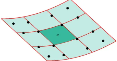
control point. Fig.2. shows the IGA element as knot spans,
where the red lines denote the knot spans and the black dots the control points of elemente.
Unlike the Lagrange elements, the IGA elements are taken to be knot spans, namely, [ni-1,ni]9[gi-1,gi], and
the control points are not always located in the element.
3.1 Element formulation for NURBS-based IGA
Shell and beam elements are required for the surface error analysis of the antenna reflector. A brief introduction of the rotation-free Kirchhoff-Love shell element based on NURBS is presented in this section. In addition, a Euler-Bernoulli beam element of three degrees of freedom based on Be´zier extraction, which maps the Bernstein polynomial basis on Be´zier elements to the NURBS basis, is developed.
3.1.1 Kirchhoff-Love Shell element
Kirchhoff-Love shell based on NURBS has been presented by KIENDL, et al [28]. The variation of the internal work formula of Kirchhoff-Love theory
dWint¼ Z
X
tecdCabcddeabþ
t3 12jcdC
abcddj
ab
dX;
eab¼
1
2 aau;bþabu;aþu;au;b
;
jab¼aa;ba3aa;ba3¼aa;ba3aa;ba3u;aba3; ð7Þ
where Cabcd denotes the elasticity tensor, eabdenotes the membrane strain, jab denotes the bending strain, aa
denotes the basis vector of middle surface in the reference configuration,uis the displacement of middle surface, and the subscript ‘,a’ denotes the derivative with respect tona, a=1, 2.
The stiffness matrix of the thin-shell element can be written as
K¼X
e
Ke¼ X
e Z
A
Et 1v2 D
m e
T
FDm e
þ Et
3
12 1ð v2Þ D
b e
T
FDbe
dA
;
ð8Þ
whereFis the transformation matrix which links the reference configuration to the deformed configuration, Dm
e and D
b e
denote the matrix for membrane and bending strains respec-tively, for details we refer the reader to BEER, et al [36].
3.1.2 Euler-Bernoulli Beam element
deflection at any point on the beam is simply the sum of the deflections caused by each of the individual loads. We developed an IGA beam loaded in such a manner that the resultant force passes through the longitudinal shear center axis, i.e. no torsion will occur.
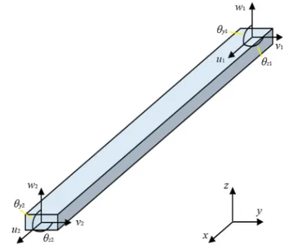
As shown in Fig.3, each node has five parameters {u,v, w, hy, hz}, where the slope h can be eliminated by
adopting standard structural-mechanics notations
hy¼
dw dx¼ w
0;
hz¼
dv dx¼ v
0;
8 > < >
: ð9Þ
where the prime symbol (•)0indicates a derivative with respect tox. The geometric equations of strains can be written as
e1ð Þ ¼x u xð Þ
0
;
e2ð Þ ¼ x yv x^ð Þ00; e3ð Þ ¼ x ^zw xð Þ00; 8
> < >
: ð10Þ
wheree1is the tensile strain and the others bending strains. The variation of the internal work formula of the beam can be obtained by using the superposition method
dWint¼ X3
a¼1 Z
Edeað Þxeað Þx
¼E A
Z l
0
du xð Þ0u xð Þ0dxþ
Iz Z l
0
dv xð Þ00v xð Þ00dx
þIy Z l
0
dw xð Þ00w xð Þ00dx
;
ð11Þ
where E denotes the Young’s modulus, A the cross-sec-tional area, Iy and Iz the second moment of inertia.
Sub-stituting Eq.6 into the internal work formula, we can obtain the stiffness matrixKin the local coordinates
K¼X
e Ke
¼EX e
AR0l R0e
T
R0edx
IzR l
0 R
00 e
T
R00edx
Iy Rl 0 R 00 e T
R00edx
0 B B @ 1 C C A:
ð12Þ
The NURBS domain can be rewritten in terms of the Bernstein basis by extracting the linear operator which maps the Bernstein polynomial basis on Be´zier elements to the NURBS basis
Reð Þ ¼n
weCeB n ð Þ
Ce ð ÞTw
h iT
Bð Þn
; ð13Þ
whereCedenotes the Be´zier extraction operator of element e[37],n=(n,g) the parametric coordinates defined over the interval [-1, 1],B(n) the Bernstein polynomial basis,w andweare two expressions for the weights of control points
w¼ w1 w2 .. . wn 0 B B B @ 1 C C C A; w
e¼
w1 0 0 0
0 w2 0 0
0 0 .. . 0
0 0 0 wn
0 B B B @ 1 C C C
A: ð14Þ
Additionally, transformation of coordinates to a com-mon global system, which will be denoted byxyzwith the local system xyz, will be necessary to assemble the ele-ments. For an element contains n control points, a trans-formation matrix Te is given to transform the forces and displacements from the global to the local system
Te 3n3n
ð Þ¼
k 0 k . . . 0 k 0 B B @ 1 C C
A; ð15Þ
withkbeing a 393 matrix of direction cosines between the two sets of axes
k¼
cosðx;xÞ cosðx;yÞ cosðx;zÞ cosðy;xÞ cosðy;yÞ cosðy;zÞ cosðz;xÞ cosðz;yÞ cosðz;zÞ 0
@
1
A: ð16Þ
Apparently, Te is an orthogonal matrix which permits the stiffness matrix of an element in the global coordinates to be computed as
Ke¼TeTKeTe: ð17Þ
3.2 Strong Coupling of the Elements
Two cases of coupling, ‘‘beam to beam’’ and ‘‘beam to shell’’, are discussed in this section. Due to the endpoint interpolation, i.e. C(-1)=P1, C(1) =Pn, of the beam
curves based on NURBS and the coincide exactly with curvature between the beam curve and the connected reflector surface shell, the strong coupling method is suit-able for the IGA-based surface error analysis.
3.2.1 Beam to beam coupling
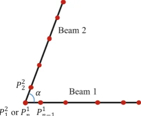
Beams join to each other with aC0-continuous connection, the angleabetween the beams is assumed unchangeable in the deformed configuration.
As shown in Fig.4,Pci denotes the ith control point of cth beam. The angle can be described by using the scalar product formula
a¼arccos P 1
nP
1
n1
P22P1n
P1
nP1n1
P2
2P1n
!
: ð18Þ
KIENDL, et al [38], proposed a bending strip method in which strips of fictitious material with unidirectional bending stiffness and zero membrane stiffness are added at patch interfaces to maintain the angle constraint. The method is efficient, simple to implement, and is applied to the coupling of ‘‘beam to beam’’ in this paper.
3.2.2 Beam to shell coupling
There are mainly two types of the ‘‘beam to shell’’ con-nection in geometrically, intersection and tangency, as shown in Fig.5. The latter one is the only type used in the surface error analysis.
As shown in Fig.6, the beam curve is equivalent to a curve on the surface shell, it’s convenient to make the control points of the beam curve coincident with that of the shell by modifying the surface. The constraint function can be described as
uCa ¼uSa; ð19Þ
where the superscriptCandS denote the displacement of theath point of beam curve and surface respectively.
3.3 RMS error analysis based on IGA shells
The IGA shell element is geometrically exact while the Langrage element is an approximation of the geometry as shown in Fig.7, the red dots denote the nodes of the Langrage element. As a result, only the nodes are available to calculate the RMS error as described in Eq.5since the pointGLin the element have inherent discretization errors. The point GI in the IGA shell element, however, is con-sidered the exact point on the surface. Thus, the arbitrary point in the IGA element is available for the calculation of the RMS error following the Eq.4.
The four vertices of the IGA shell element, i.e.n =(-1, 1), (-1, 1), (1, -1), (1, 1), are adopted to determine the unknowns of the best-fit surface by the least square method. The normal deviation of the arbitrary point on the surface can be written as
Dið Þ ¼n Y uð ið Þn ;við Þn ;wið Þn Þ: ð20Þ
The RMS error can then be described as
Fig. 4 ‘‘Beam to beam’’ coupling
Fig. 5 Two types of ‘‘beam to shell’’ coupling, intersection (left) and tangency (right)
Fig. 6 Red dots denote the control points of beam and shell
erms¼
ffiffiffiffiffiffiffiffiffiffiffiffiffiffiffiffiffiffiffiffiffiffiffiffiffiffiffiffiffiffiffiffiffiffiffiffiffiffiffiffiffiffiffiffiffiffiffiffiffiffiffiffiffiffiffiffiffiffi P
e R
e Y ue
ið Þn;veið Þn;weið Þn
ð Þ
½ 2
1þ reið Þn
2f
2 dA
" #
A
v u u u u t
:
ð21Þ
The Gauss quadrature is adopted to solve the equation
erms¼
ffiffiffiffiffiffiffiffiffiffiffiffiffiffiffiffiffiffiffiffiffiffiffiffiffiffiffiffiffiffiffiffiffiffiffiffi P
e Pgp
j¼1Qe nj
jj
A
s
; ð22Þ
where
Qe nj
¼ Y u
e i nj
;ve i nj
;we i nj
2
1þ reið Þnj 2f
2 ;
jjis the weight of the gauss point. The equation is similar
with Eq.5, but however they are different in essence.
4 Numerical Examples
In the following, two numerical examples are presented to reveal the overall performance of the three dimensional Euler-Bernoulli Beam IGA element and the application of
IGA in RMS error analysis. First, a Cantilever beam sub-jected to a point force is introduced to verify the accuracy of the beam element with the analytical solution. And then a parabolic antenna modeled by the Kirchhoff-Love shell and Euler-Bernoulli Beam IGA element is prepared for the RMS error analysis.
4.1 Cantilever beam
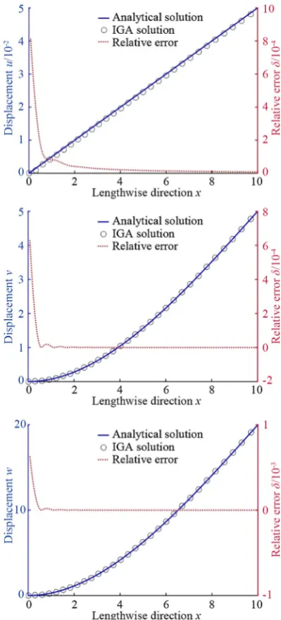
The Cantilever beam is subjected to a point force ofF= (1, 1, 1)Ton the right end point, and is fixed on the left end point, as shown in Fig.8. The problem is often used as a benchmark to verify the accuracy of the developed beam element.
Fig. 8 Cantilever beam problem description
Fig. 9 Discretization of the cantilever beam and its control points (blue dots)
In our calculations, the geometric and material param-eters are assumed as follows: the lengthL=10; the thick-nesst=1; the widthb=2; the Young’s modulusE=100. The analytical solution can be obtained from
u xð Þ ¼ Fx EAx; v xð Þ ¼ Fy
6EIz
3Lx2x3
;
w xð Þ ¼ Fz 6EIy
3Lx2x3
;
8 > > > > > > < > > > > > > :
ð23Þ
where A=bt, Iy=t3b/12, Iz =b3t/12. The cantilever
beam is then discretized by 16 IGA Euler-Bernoulli beam elements as shown in Fig.9, the blue dots denote the control points. For a cubic basis function, each element contains 4 control points (The red diamonds denote the control points of element 1 and the red squares the control points of element 9).
The results comparisons between analytical solutions and IGA solutions are shown in Fig.10. The maximum relative errorsdof the deformation in the three directions are less than 0.1%, which means the IGA beam element exhibits a high accuracy.
4.2 Surface error analysis of a reflector antenna
The IGA shell and beam elements are now applied to the
RMS error analysis of the reflector. In this analysis the antenna is subjected to a gravity load and a wind load corresponding toc= 20 m/s wind at a working angle of 45 degrees, as shown in Fig. 11.
The assembly is composed of a main reflector and a bracket, and is discretized by the IGA shell and beam elements respectively. The ‘‘beam to shell’’ method is applied to couple the reflector surface and the bracket while the ‘‘beam to beam’’ method is applied to couple the beams of the bracket. Three types of beam are adopted to con-struct the bracket as shown in Fig.12.
The IGA model and traditional finite element model are shown in Fig. 13.
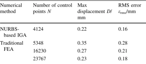
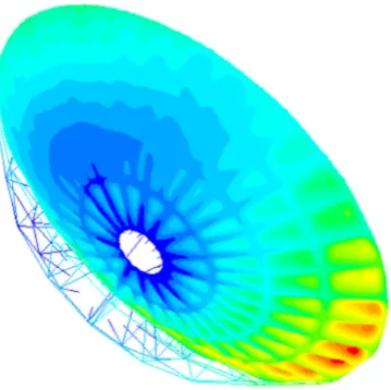
As listed in Table1, NURBS-based IGA and traditional FEA are employed in convergence analysis by calculating the max displacement and the RMS error of the model with a different number of control points or nodes under the gravity and wind load. Here, N denotes the number of control points in IGA and nodes in ANSYS. It is clear that the IGA approach rapidly converges at about N=4124 while the traditional FEA simulation reaches the same convergence value until the nodes increase to 23767 both for the value of the maximum displacement and RMS error. The deformation result of IGA is presented in Fig.14. The surface distortion along the radius of the reflector at the angle of 0and 90are presented in Fig.15. Fig. 11 Main reflector (yellow) and bracket (blue) of a reflector
antenna. Problem description
Fig. 12 Three types of beam
Fig. 13 IGA model with 4124 control points (left) and FEA model with 23767 nodes (right)
Table 1 Convergence analysis of max displacement and RMS error Numerical
method
Number of control pointsN
Max
displacementD/ mm
RMS error erms/mm
NURBS-based IGA
4124 0.22 0.16
Traditional FEA
5348 0.35 0.28
16230 0.27 0.21
5 Conclusions
(1) A new IGA beam element is developed by inte-grating the displacement field of the element, which is approximated by the NURBS basis, with the internal work formula of Euler-Bernoulli beam the-ory with the small deformation and elastic assumptions.
(2) Two cases of coupling, ‘‘beam to beam’’ and ‘‘beam to shell’’, are discussed. Due to the endpoint interpolation of the beam curves based on NURBS and the coincide exactly with curvature between the beam curve and the connected reflector surface shell, the strong coupling method is suitable for the IGA-based surface error analysis.
(3) Due to the geometrically exact no matter how coarse the discretization is and the higher-order basis func-tions, the IGA method is able to achieve the accurate solution with less degrees of freedom than traditional FEA and the arbitrary point in the IGA element is available for the calculation of the RMS error.
(4) The cantilever beam benchmark problem was chosen to demonstrate the good performance of the devel-oped IGA beam element. The maximum relative errors of the deformation in the three directions between analytical solutions and IGA solutions are less than 0.1%.
(5) An antenna model, which is composed of a main reflector and a bracket, is discretized by the IGA shell and beam elements respectively. By coupling the elements strongly, the IGA method is applied in the functional surface error analysis of the antenna reflector successfully. It is clear that the IGA approach reaches the convergence precision with much less control points than traditional FEA.
Open Access This article is distributed under the terms of the Creative Commons Attribution 4.0 International License (http://crea tivecommons.org/licenses/by/4.0/), which permits unrestricted use, distribution, and reproduction in any medium, provided you give appropriate credit to the original author(s) and the source, provide a link to the Creative Commons license, and indicate if changes were made.
References
1. UKITA N, EZAWA H, IKENOUE B, et al. Thermal and wind effects on the azimuth axis tilt of the ASTE 10-m antenna[J]. Publ. Natl. Astron. Obs. Japan, 2007, 10: 25–33.
2. XIA Xintao, WANG Zhongyu. Grey relation between nonlinear characteristic and dynamic uncertainty of rolling bearing friction torque[J]. Chinese Journal of Mechanical Engineering, 2009, 22(2): 244–249.
3. LIU Zhenyu, TAN Jianrong, DUAN Guifang, et al. Force feed-back coupling with dynamics for physical simulation of product assembly and operation performance[J]. Chinese Journal of Mechanical Engineering, 2015, 28(1): 161–172.
4. YI Wei, JIANG Zhaoliang, SHAO Weixian, et al. Error com-pensation of thin plate-shape part with prebending method in face milling[J]. Chinese Journal of Mechanical Engineering, 2015, 28(1): 88–95.
5. WANG M, WANG W, WANG C S, et al. A practical approach to evaluate the effects of machining errors on the electrical perfor-mance of reflector antennas based on paneled forms[J]. IEEE Antennas & Wireless Propagation Letters, 2014, 13(13): 1341–1344.
6. ROY L. Structural engineering of microwave antennas: for electrical, mechanical and civil engineers[M]. 1th edition. New York: I.E.E.E. Press, 1996.
7. TANAKA H. Surface error estimation and correction of a space antenna based on antenna gain analyses[J]. Acta Astronautica, 2011, 68(7): 1062–1069.
8. XIE Y M, SHI H, ALLEYNE A, et al. Feedback shape control for deployable mesh reflectors using gain scheduling method[J].Acta Astronautica, 2016, 121: 241–255.
9. SMITH I A. JCMT active surface control system: implementa-tion[J].Proceeding of SPIE-The International Society for Optical Engineering, 1998, 3351: 190–196.
10. TANAKA H, NATORI M C. Shape control of space antennas consisting of cable networks[J]. Acta Astronaut, 2004, 55(3): 519–527.
Fig. 14 Deformation result under the gravity and wind load calcu-lated by IGA
11. WANG W, DUAN B Y, LI P, et al. Optimal surface adjustment by the error-transformation matrix for a segmented-reflector antenna[J]. IEEE Antennas and Propagation Magazine, 2010, 52(3): 80–87.
12. LIU K K, YE Q, MENG G X. Surface error diagnosis of large reflector antenna with microwave holography based on active deformation[J].Electronics Letters, 2016, 52(1): 12–13. 13. ELDAR Y C, MENDELSON S. Phase retrieval: stability and
recovery guarantees[J]. Appl. Comput. Harmon. Anal., 2014, 36(3): 473–494.
14. JENNINGS A, MAGREE D, BRIGGS G, et al. Texture-based photogrammetry accuracy on curved surfaces[C]// Structural Dynamics and Materials Conference, Orlando, USA, APRIL 12–15, 2010: 1060–1071.
15. YOON H-S. An optimal method of shape control for deformable structures with an application to a mechanically reconfigurable reflector antenna[J].Smart Materials & Structures, 2010, 19(10): 533–536.
16. YOU B D, WEN J M, ZHAO Y. Nonlinear analysis and vibration suppression control for a rigid–flexible coupling satellite antenna system composed of laminated shell reflector [J]. Acta Astro-nautica, 2014, 96(1): 269–279.
17. DU J L, BAO H, CUI C Z. Shape adjustment of cable mesh reflector antennas considering modeling uncertainties[J]. Acta Astronautica, 2014, 97(2): 164–171.
18. HUGHES T J R, COTTRELL J A, BAZILEVS Y. Isogeometric analysis: CAD, finite elements, NURBS, exact geometry and mesh refinement[J]. Comput. Methods Appl. Mech. Eng., 2005, 194: 4135–4195.
19. COTTRELL J A, REALI A, BAZILEVS Y, et al. Isogeometric analysis of structural vibrations[J].Comput.Methods Appl.Mech. Engrg., 2006, 195(41): 5257–5296.
20. DO¨ RFEL M R, JU¨TTLER B, SIMEON B. Adaptive isogeometric analysis by local h-refinement with T-splines[J].Comput. Meth-ods Appl.Mech.Engrg., 2010, 199(5): 264–275.
21. CHEN L, NGUYEN-THANH N, NGUYEN-XUAN H. Explicit finite deformation analysis of isogeometric membranes[J]. Com-put.Methods Appl.Mech.Engrg., 2014, 277(277): 104–130. 22. BAZILEVS Y, HSU M C, SCOTT M A. Isogeometric fluid–
structure interaction analysis with emphasis on non-matching discretizations, and with application to wind turbines[J].Comput. Methods Appl.Mech.Engrg., 2012, 249–252(249): 28–41. 23. WALL W A, FRENZEL M A, CYRON C. Isogeometric
struc-tural shape optimization[J]. Comput. Methods Appl.Mech. En-grg., 2008, 197(33–40): 2976–2988.
24. SEO Y-D, KIM H-J, YOUN S-K. Shape optimization and its extension to topological design based on isogeometric analy-sis[J]. International Journal of Solids and Structures, 2010, 47(11–12): 1618–1640.
25. HASSANI B, KHANZADI M, TAVAKKOLI S M. An isogeo-metrical approach to structural topology optimization by opti-mality criteria[J].Struct Multidisc Optim., 2012, 45(2): 223–233. 26. TAVAKKOLI S M, HASSANI B. Isogeometric topology opti-mization by using optimality criteria and implicit function[J].Int. J.Optim.Civil Eng., 2014, 4(2): 151–163.
27. BUFFA A, SANGALLI G, VA´ ZQUEZ R. Isogeometric methods for computational electromagnetics: B-spline and T-spline dis-cretizations[J].Journal of Computational Physics, 2014, 257(2): 1291–1320.
28. KIENDL J, BLETZINGER K-U, LINHARD J, et al. Isogeo-metric shell analysis with Kirchhoff–Love elements[J].Comput. Methods Appl.Mech.Engrg., 2009, 198(49–52): 3902–3914 29. DORNISCH W, KLINKEL S, SIMEON B. Isogeometric Reissner–
Mindlin shell analysis with exactly calculated director vectors[J]. Comput.Methods Appl.Mech.Engrg., 2013, 253(1): 491–504. 30. GRECO L, CUOMO M. An implicit G1 multi patch B-spline
interpolation for Kirchhoff–Love space rod[J].Comput.Methods Appl.Mech.Engrg., 2014, 269(1): 173–197.
31. RUESS M, SCHILLINGER D, O¨ ZCAN A I, et al. Weak cou-pling for isogeometric analysis of non-matching and trimmed multi-patch geometries[J].Comput.Methods Appl.Mech.Engrg., 2014, 269(2): 46–71.
32. GUO Y, RUESS M. Nitsche’s method for a coupling of isoge-ometric thin shells and blended shell structures[J]. Comput. Methods Appl.Mech.Engrg., 2015, 284: 881–905.
33. WANG D, XUAN J. An improved NURBS-based isogeometric analysis with enhanced treatment of essential boundary condi-tions[J]. Comput. Methods Appl. Mech. Engrg., 2010, 199 (37–40): 2425–2436.
34. EMBAR A, DOLBOW J, HARARI I. Imposing dirichlet boundary conditions with nitsche’s method and spline-based finite elements[J]. Int. J. Numer. Meth. Engng., 2010, 83(7): 877–898.
35. RUZE J. Antenna tolerance theory-A review[J]. Proc. IEEE., 1996, 54(4): 633–640.
36. BEER G, BORDAS S. Isogeometric methods for numerical simulation[M]. Springer Vienna, 2015.
37. BORDEN M J, SCOTT M A, EVANS J A, et al. Isogeometric finite element data structures based on Be´zier extraction of NURBS[J].Int.J.Numer.Meth.Engng., 2011, 87: 15–47. 38. KIENDL J, BAZILEVS Y, HSU M-C, et al. The bending strip
method for isogeometric analysis of Kirchhoff–Love shell structures comprised of multiple patches[J]. Comput. Methods Appl.Mech.Engrg., 2010, 199(37–40): 2403–2416.
Pei YUAN,is currently a doctoral candidate atState Key Laboratory of CAD&CG,Zhejiang University,China. His interests include CAD, sensitivity analysis and isogeometric analysis. E-mail: [email protected]
Zhenyu LIU, is currently a professor at State Key Laboratory of CAD&CG,Zhejiang University,China. His research interests include CAD, virtual prototyping, virtual-reality-based simulation, and robotics. E-mail: [email protected]