Construction of virtual mulch film model based on discrete element
method and simulation of its physical mechanical properties
Wensong Guo
1,2,
Can Hu
1*,
Xiaowei He
1,
Long Wang
1,
Shulin Hou
2,
Xufeng Wang
1* (1. College of Mechanical and Electrical Engineering, Tarim University, Alar 843300, Xinjiang, China;2. College of Engineering, China Agricultural University, Beijing 100083, China)
Abstract: In China, especially in Xinjiang Region, mulch film remaining in the soil has severely jeopardized the safety of soil resources. To numerically simulate the residual film-soil-recovery implementation system, a virtual mulch film model with consistent physical and mechanical properties with real mulch film needs to be established. In this study, a flexible deformable virtual mulch film model was constructed using YADE software based on the Minkowski Sum principle and the ball-ball force-displacement constitutive rule, as well as the contact failure rule were established. The deformation behaviors of cylinders and PFacet elements, such as stretching, bending, and torsion, were described. By splicing the basic PFacet elements, a virtual mulch model was established. The mechanical model of a virtual mulch film under tension was established and the axial tensile stiffness coefficient kn was determined to be 43.30 N·m. To verify the physical and mechanical properties
of this virtual mulch film, both real and virtual stretching and tearing tests were conducted. The experimental results showed that: in the process of stretching and tearing of real and virtual films, the properties of morphological features of both are basically identical; however, they clearly differ in force-displacement. The viscoelastic constitutive model between balls and yield judgment conditions requires further study.
Keywords: discrete element method, mulching film, physical and mechanical properties, virtual test DOI: 10.25165/j.ijabe.20201304.5525
Citation: Guo W S, Hu C, He X W, Wang L, Hou S L, Wang X F. Construction of virtual mulch film model based on discrete element method and simulation of its physical mechanical properties. Int J Agric & Biol Eng, 2020; 13(4): 211–218.
1 Introduction
China has introduced under-film drip irrigation technology since the 1970s, which has greatly increased the utilization efficiency of water resources and crop output. Because of the high labor intensity, high recycling costs, immaturity of the required recycling equipment, and farmers' lack of attention for the recycling of plastic mulch film, a large amount of mulch film is not recycled and has been buried in the tillage soil layer. According to a survey conducted by the Agriculture Department of Xinjiang Uygur Autonomous Region, China, the average residual mulch film in the soil in Xinjiang has reached 268.65 kg/hm2. This severely jeopardizes the safety of agricultural soil resources in Xinjiang Region[1-5].
The Chinese Government has paid much attention to residual-film pollution in tillage soil. At present, the recycling methods for this type of pollution are mainly via rotary tiller, chain sieve, excavation screening, shovel, chain rake, and other instruments[6-11]. The process of recycling residual film from
Received date: 2019-11-17 Accepted date: 2020-05-18
Biographies: Wensong Guo, PhD candidate, Associate Professor, research
interests: intelligent agricultural equipment, Email: [email protected]; Xiaowei He, PhD candidate, Lecturer, research interests: agricultural equipment, Email: [email protected]; Long Wang, PhD candidate, Lecturer, research interests: soil machinery, Email: [email protected]; Shulin Hou, Professor, interests: agricultural equipment, [email protected].
*Corresponding author: Can Hu, PhD candidate, Lecturer, research interests:
intelligent agricultural equipment, detailed address, telephone number, Email: [email protected]; Xufeng Wang, PhD, Professor, research interests: agricultural equipment. College of Engineering, Tarim University, 843300, Alar, Xinjiang, China. Tel: +86-13779803762, Email: [email protected].
tillage soil involves interaction with residual film-soil-recycling machinery. To conduct numerical simulation research on this type of interaction, the first important task is to construct a virtual plastic mulch film and ensure that the virtual model has the same physical and mechanical properties with real mulch film[12,13].
In China, most scholars used the finite element method to construct membranes. Wenet al.[14] used the software ANSYS to analyze the natural vibration characteristics of cable-membranes. Han et al.[15] performed a finite element simulation of an inflatable membrane, based on LS-DYNA. Jin[16] used ADINA software to perform a finite element simulation of tensile membranes.
Lobo-Guerrero et al.[17] constructed a flexible film using the discrete element method (DEM). Tran et al.[18] studied geogrid-soil interaction using the finite-discrete coupling method. Effeindzourou et al.[19] proposed a general method for the building of deformable and arbitrarily shaped object models under the DEM framework. Thoeni[20] used the Minkowski sums method to establish a discrete element model of geotextile.
Both geotextiles and mulch films are flexible, but their features are significantly different in thickness, strength, and structural composition. Therefore, the construction of virtual mulch differs from geotextile construction. In this paper a physical model of mulch film was established based on the Minkowski sums method under the framework of DEM. For this, virtual stretching and tearing simulation were used to verify the physical and mechanical properties of the virtual mulch film.
2 Methods for virtual mulch film construction
2.1 Particle cluster method
Figure 1 shows the particle clustering method in which a multitude of spherical particles are added and joined to form a flexible film. Spherical particles are allowed to move relative to each other, thus enabling flexible deformation. However, adjacent spherical particles are in point contact, and there is a gap between them. The existence of the resulting pores results in the surface of a flexible membrane to not be smooth, i.e., producing artificial surface roughness. Therefore, virtual mulch constructed by particle clustering is significantly different from a real smooth mulch film.
Figure 1 Virtual film structure using the particle cluster method
2.2 Minkowski sums method
The Minkowski sums theory superimposes two arbitrary spatial bodies in Euler coordinates and forms a new space body. In the extended particle model, a space body can adopt a straight line, a disk, a rectangle, or a polyhedron. The base unit can be simplified as a sphere. The expansion unit can be regarded as covering a surface of the base unit with a layer of an expanding sphere, the center of gravity of which is located on the surface of the basic unit body. Since the basic unit can be set to any shape, the extended sphere can be of any size and can be expanded into units of any shape based on this method.
A membrane constructed by the Minkowski sums method has a smooth surface, no artificial surface roughness, and has a more similar appearance to the real film. Therefore, this method was chosen in this study. YADE is the only discrete element software that enables the creation of a film structure using the Minkowski sums method. Therefore, YADE was used.
3 Discrete element method based on ball-ball contact
rule
The ball-ball contact constitutive rule is the basic constitutive rule for the construction of the virtual mulch film model by the DEM. The types of spherical particles that currently constitute the DEM are classified into rigid-ball and soft-ball model. This paper adopts the rigid-ball model, which does not allow deformation. The ball-ball contact constitutive rule is mainly composed of the force-displacement rule and the contact failure rule.
3.1 Force-displacement rule
The force-displacement rule of ball-ball contact is shown in Figure 2. Only an axial remote virtual contact force is considered, while mutual torsion, friction, and scroll are ignored.
The contact force F was only considered between adjacent
balls, and the direction F is the direction of the line that connects the center of ball A and B, as shown in Equation (1):
( AB AB)
n eq
Fk d D n (1)
where, kn represents the equivalent normal contact stiffness
coefficient; dAB represents the actual distance between the centers of ball A and B; DeqAB represents the equilibrium distance between
the centers of ball A and B; n represents a unit vector with the direction from the center of ball A to that of ball B.
When dABDeqAB , the axial contact force is zero; when
AB AB eq
d D , the contact force is tensile; when dABDeqAB, the
contact force is compressive. Because of the flexible physical properties of mulch film, the compression phenomenon was not
considered, i.e., only the cases of dABDeqAB and
AB AB eq
d D
were considered.
Because the thickness of mulch film is typically 0.01 mm, the flexibility of mulch film is particularly high; therefore, the contact torque of mulch film was ignored.
Figure 2 Force-displacement constitutive model of ball-ball contact
3.2 Contact failure rule
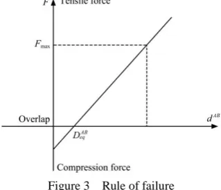
The damage modes of mulch film were mainly tensile failure and tear failure, regardless of bending and torsion damage. The same failure rule was adopted for tensile failure and tear failure, i.e., when the tensile force between particles exceeds the ultimate connection force, the connection between particles fails and the membrane unit breaks. The rule of failure is shown in Figure 3.
max
||Fn||AFn (2) where, σ represents the tensile strength, and A represents the equivalent contact area.
When the tensile force exceeds the tensile limit, this results in tensile failure, the virtual mulch film breaks, the tensile force becomes zero, and the bending and torsional moment also become zero.
Figure 3 Rule of failure
4 Virtual mulch film construction
4.1 Cylinder element
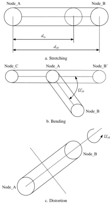
A cylinder corresponds to Minkowski sums of a ball and a line segment; therefore, it does not introduce any numerical roughness compared with a bounded particle model. It can withstand tensile, shear, bending, and torsional loads. The deformability of a cylinder is defined by the position and orientation of its two nodes. Figure 4 shows the stretching, bending, and torsion of a cylinder element.
As shown in Figure 4a, when the distance dAB between both
ends of the cylinder exceeds the equilibrium distance deq, tensile
force, equivalent to the tensile deformation of a cylinder, is generated in the axial direction. As shown in Figure 4b, when
node B rotates around node A, bending deformation occurs, b AB
represents the bending angle; as shown in Figure 4c, when node B rotates around the normal of nodes A and B, a torsional
deformation occurs, t AB
represents the torsion angle.
a. Stretching
b. Bending
c. Distortion
Figure 4 Deformation behaviors of a cylindrical unit
4.2 PFacet element
PFacet element is represented by a triangle line segment and a sphere through Minkowski sums. As shown in Figure 5, PFacet element consists of three nodes and three interconnected cylinders. The mechanical behavior can be represented by three cylinders. PFacet is similar to three connected cylinders. The difference is that a PFacet element has two contact surfaces (top surface and bottom surface), and the contact between these surfaces and other particles is defined by two contact surfaces; the thickness of PFacet depends on the diameter of spherical particles at the node.
The deformation behavior of a PFacet element is defined by changes in the coordinates and orientation of the three nodes. The mechanical behavior of a PFacet element is calculated by the constitutive law between the balls at the joint.
Figure 5 Triangle face unit
Figure 6 shows the deformation behavior of the PFacet element. Figure 6a shows tensile deformation, and when the PFacet element is subjected to tensile force, tensile deformation occurs. Figure 6b shows fracture failure, in which two PFacet elements are connected, and when the connection of the two PFacets is subjected to a force that exceeds the ultimate joint force, the joint fails and breaks into two PFacet elements. This is equivalent to the fracture failure of the film. Figure 6c shows bending and distortion deformations, when node C is subjected to forces in the non-AC and BC directions, while node D is subjected to forces in the non-AD and BD directions. Consequently, the PFacet unit will be subject to bending and distortion deformation.
a. Tensile deformation
b. Fracture failure
c. Bending and distortion deformation
Figure 6 Deformation behavior of PFacet elements
4.3 Establishment of a virtual mulch film model
structures. The topology shown in Figure 7a is asymmetric, Figure 7b shows a symmetric topology. Therefore, the mechanical properties of the topology shown in Figure 7b in all directions are consistent and continuous. In the end, the topology shown in Figure 7b was used to construct the virtual mulch film model.
At present, because of the requirements of the manufacturing process, polyethylene mulch has different mechanical properties in lateral and longitudinal directions. Because of topology, the virtual mulch with Topology 2 structure has the same mechanical properties in lateral and longitudinal directions. Many research tasks are still required to build a more realistic virtual mulch film.
a. Topology 1 b. Topology 2 Figure 7 Topological mechanism of virtual mulch film
It is required following a number of assumptions to splice discrete PFacet elements into a virtual mulch film model:
1) The quality of virtual mulch film is concentrated on the nodes;
2) Force and moment only exist in adjacent nodes;
3) The node-node distance is very large with respect to the diameter of the balls, independent of the friction between adjacent particles;
4) The diameter of the balls (0.01 mm) is equivalent to the thickness of the virtual mulch film.
The virtual mulch film is finally constructed as shown in Figure 8.
a. Topology b. Virtual model
c. Real mulch film
Figure 8 Discrete element model of mulch film
5 Verification test of the physical and mechanical
properties of the virtual film
5.1 Determination of the axial stiffness coefficient
Figure 9 shows a schematic diagram of stretching real mulch film and virtual mulch film model.
a. Real stretching b. Virtual stretching Figure 9 Schematic diagram of real and virtual stretching
Figure 9 shows that the virtual mulch film mode is equivalent to a simple truss mechanism, where only adjacent nodes can withstand the tensile force; however, the real mulch film is a continuous body, and can thus withstand continuous tension. Therefore, the axial stiffness coefficient of the virtual mulch film model cannot be simply transformed by the elastic modulus of real mulch film. To ensure consistent tensile performance between virtual and real plastic mulch films, the following assumptions are made.
1) At the initial stretching stage, the virtual film is only displaced in the XOY plane, and does not undergo any prestress;
2) The gravity of the virtual film model is ignored;
3) Moments between particles in the XOY plane are ignored; 4) For small tensile displacement, transverse shrinkage deformation is ignored.
As shown in Figure 9, the initial distance between adjacent lateral and longitudinal nodes is defined as u (unit: mm), d
represents the radius of the ball, D=2d is the equivalent thickness of virtual mulch. When real and virtual mulch film both stretch for a length of ∆l, the tensile forces are F1 and F2, respectively.
F1=F2 should be satisfied when stretching for the same length.
The relationship between tensile force and displacement of real mulch film is as follows:
1 . . . .
l l
F A E W D E
L L
(3)
where, A represents the cross-sectional area of real film, A=W.D,
W represents the width of real mulch film, D represents the thickness of real and virtual mulch film; E represents the elastic modulus of real mulch film; ∆l represents the stretch length of real and virtual mulch film, and L represents the length of real and virtual mulch film.
FS3= FS0S3+FS2S3+FS4S3 (4)
FS3= F
X S3+F
Y
S3 (5)
where, FS0S3 represents the force of node 0 to node 3; FS2S3
represents the force of node 2 to node 3; FS4S3 represents the force
of node 4 to node 3; FXS3 represents the resultant force in the
horizontal direction, and FYS3 represents the resultant force in a
vertical direction.
Figure 10 Basic primitives of the discrete model of mulch film
Because of the symmetry of the basic primitive, the resultant force FYS2 of particle 2 is equal to F
Y S3.
FYS3= F
Y
S2 (6)
Then, when the base primitive is stretched Δl′ in the vertical direction.
Fu=F Y S3+F
Y S2=2F
Y
S2 (7)
where, Fu represents the resultant pulling force of the base
primitive.
According to the constitutive law of the discrete element method, Equation (8) can be obtained.
0 3 4 3 2 3 1 1 2 2 ( )
( ) cos
0 Y
S S n eq
Y
S S n eq
Y S S
F K D D
F K D D
F (8)
where, D1 represents the distance between nodes 0 and 3; D 1
eq
represents the equilibrium distance between nodes 0 and 3; D2
represents the distance between nodes 4 and 3; D2eq represents the
equilibrium distance between nodes 4 and 3, and θ represents the angle between the line direction of nodes 4 and 3 and horizontal direction.
According to initial conditions, Deq1 u, 2 2 2 eq
D u, and
4 I
. The following Equations can be obtained when the
stretching length is Δl′:
1
1 eq
D D l (9)
2 2
2 ( / 2) ( 1/ 2)
D u D (10)
1 1 / 2 arctan arctan / 2 u u D D
(11)
Then, the resultant force FYS3 can be calculated.
3 0 3 4 3 2 3
2 2
1
1
2
( / 2) ( / 2)
2
cos(arctan )
Y Y Y Y
S S S S S S S n n
F F F F k l k u D u
u D (12) According to the relationship between the base primitive and virtual mulch film stretching model, the following Equations can be
obtained:
L
l l
u
(13)
3 2 1 Y S W F F u
(14)
where, F2 represents the virtual stretching force.
Combining and simplifying the above Equations yields the following:
2 2
2 1
1
2
1 ( / 2) ( / 2)
2
cos(arctan )
n n
W
F k l k u D u
u u D (15)
When Δl′ is very small,
4
, 2 2 1
( / 2)u (D / 2)
2 2
1 1 1
2
( / 2) ( / 2)
2
D D D.
Equation (16) can be obtained by simplifying Equation (15).
2 1
2 2 2
( 1) ( 1)
2 2 2
1 3
( 1)
2 2
n n
n n n
W W
F k l k D u
u u
W l u
k l k l k
u L (16)
Therefore, F1=F2 can be converted into the following
Equation:
3
( 1)
2 n
l W l u
WDE k
L u L
(17)
Equation (18) can be obtained by simplifying Equation (16).
(18)
The following conclusion can be obtained from Equation (18): The tensile stiffness coefficient of the virtual model is related to the elastic modulus E, initial adjacent node distance u, length W, and thickness D of the real mulch. Therefore, when setting the axial stiffness of the virtual mulch film, all the above-mentioned parameters should be considered comprehensively.
From the tensile test of mulch film, the elastic modulus of real mulch film is E=6.82 MPa. The thickness of the mulch film is
D=1e−5 m. The width of the test mulch is W=2e−2 m. The equilibrium distance between adjacent particles is D1eq=1 mm. By
calculating Equation (18), the value of the axial stiffness coefficient
Kn is 43.3 N·m.
6 Results of the virtual simulation test
To verify whether virtual mulch film has similar physical and mechanical properties to real mulch film, stretching and tear contrast tests of virtual and real mulch film were conducted. 6.1 Stretching test
(1) Test method
was 50±5 mm/min.
The method of virtual stretching is shown in Figure 9b. At the fixed end, the six degrees of freedom of the spherical particles are completely restricted and therefore cannot be moved. At the stretched end, only one translational freedom of the stretching directions is retained. Other particles do not impose any constraints. Finally, the spherical particles at the stretched end are subjected to the same constant speed as caused by real stretching in the stretching direction.
(2) Tensile results
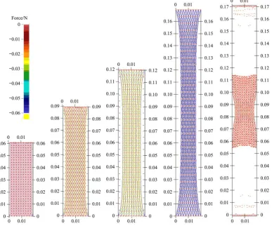
Figure 11 shows the results of real film stretching, Figure 12 shows the simulation results of virtual film stretching, and Figure 13 shows the relationship between tensile displacement and tensile force.
A comparison between Figure 11 and Figure 12 shows 1) Elongation change: the tensile elongation of real mulch film was 183%, and the tensile elongation of the virtual mulch film was 200%. The elongation changes of both are basically identical. 2) Morphological changes: Before tensile fracture, the longitudinal shrinkage morphology of both are basically identical; after tensile fracture, the real residual film has yielded to deformation and the deformed residual film cannot be recovered. Virtual mulch film did not yield to deformation after fracture, and the fractured residual membrane recovered rapidly. 3) Fracture position: The fracture position of the real mulch film sample was the middle part; the fracture position of the virtual mulch film sample was at approximately the tensile clamping end.
Figure 15 shows that the tensile force-displacement curve of real mulch film indicates the process of elastic deformation-yield-fracture; the virtual mulch film model indicates the process of elastic deformation-fracture. The difference
between the force-displacement laws of both during the stretching process is obvious.
Analysis of the reasons: The current particle contact law is an ideal spring model; therefore, the deformation of the virtual mulch is equivalent to a linear deformation. The deformation of the real mulch film is plastic deformation. To describe the plastic deformation behavior, the viscoelastic model should be further studied. The existing particle contact constitutive rules have not set the yield judgment conditions, i.e., when the deformation of the PFacet element reaches the set value, the deformation cannot be recovered. Further work is needed to establish and verify the yield rule.
Figure 11 Results of physical stretching (length units: m)
Figure 13 Force-displacement curves of virtual and actual tensile
6.2 Tearing test (1) Tearing method
The real tearing test is shown in Figure 14a. This method adopts the Chinese national standard GB/T16578-2008 “Test method for tear resistance of plastic film and sheet-pants tearing method”. The tearing sample was prepared by cutting a slit of a certain length into the middle of a rectangular mulch film, resulting in the final sample akin to a pair of pants; therefore, this method is called the pants-shaped tearing method. The film tearing force was defined as the force required to tear the crack along the slit at a constant tear speed. The test speed was 200±20 mm/min, and the length of clamping was 30 mm.
The virtual tearing method is shown in Figure 14b. The five degrees of freedom of spherical particles of the upper and lower end are limited, and all particles have only one translational degree of freedom in the tear direction. Other particles do not limit any degree of freedom. Under the virtual stretching, the spherical particles at both the upper and lower end are moved in the upper and lower tearing directions, respectively, and the velocity value is the same as in the real tearing test.
a. Real tear
b. Virtual tear
Figure 14 Schematic diagram of real and virtual tearing
(2) Tearing results
Figure 15 shows the tearing results of real mulch film, Figure 16 shows the tearing results of virtual mulch film, and Figure 17 shows the relationship between tearing force and displacement of both virtual and real mulch films.
Figure 15 Results of physical tear (length units: m)
Figure 16 Results of virtual tear (length units: m)
Figure 17 Virtual and actual tear force-displacement curves
Figure 17 shows that during real tearing, the tearing force first gradually increases, then gradually decreases when the tearing force increases to the maximum until tearing is completed. During virtual tearing, the tearing force gradually increases, then, suddenly becomes smaller, and then gradually increases again; this process reciprocates until the tear is complete.
Analysis of the reason: the virtual mulch model is a discrete structure, similar to a truss, rather than a continuous surface structure, when a node breaks, the tearing force changes suddenly.
7 Conclusions
(1) A flexible and deformable virtual mulch film model was constructed based on the Minkowski sums principle. The ball-ball particle force-displacement contact constitutive rule and the contact failure rule are established. Deformation behaviors such as stretching, bending, and torsion of the flexible cylinder and PFacet element were defined. The virtual mulch film model was finally established by programming and splicing of PFacet elements.
(2) To ensure that the established virtual mulch model has the same physical and mechanical properties as real mulch film, and to determine the physical parameters of virtual mulch film, a mechanical model of virtual mulch film was established by mathematical analysis during stretching. When the elastic modulus value of the real mulch film is 6.82 MPa, the thickness D is 1e−5 m, the width W is 2e−2 m, and the equilibrium distance between adjacent particles D1eq is 1 mm. By solving the
mathematical model, the axial tensile stiffness coefficient k was identified as 43.3 N·m.
(3) The real and virtual stretching results are as follows:
① The tensile elongations of real and virtual mulch films were 183% and 200%, respectively. ② Real mulch film has yield deformation and the deformed residual film cannot be recovered. For virtual mulch film, there was no yield deformation after a fracture. ③ The fracture position of real and virtual mulch film samples is at the middle and around the tensile clamping end, respectively. ④ The tensile force-displacement curve of real and virtual mulch films show the process of elastic deformation-yield- fracture and elastic deformation-fracture, respectively.
(4) The real and virtual tear test results were as followsthat the tear elongations of virtual and real mulch film were 230.8% and 217.7%, respectively; The morphological characteristics of virtual and real mulch film during the tearing process are basically identical; The tear force-displacement curves of both differ completely.
(5) In the process of stretching and tearing of real and virtual films, the properties of morphological features of both are basically identical; however, the difference in force-displacement is apparent. The viscoelastic constitutive model between balls and yield judgment conditions requires further study.
Acknowledgements
This work was financially supported by the Xinjiang Production and Construction Corps Major Technology Project (2018AA001/03), the China 13th Five-Year Key Research and Development Plan (2017YFD0701102-1), the Corps Key R&D Projects (2019AB007), and the China National Natural Science Foundation Project (11562019).
[References]
[1] Hu C, Wang X F, Wang S G, Lu B, Guo W S, Liu C J. Impact of agricultural residual plastic film on the growth and yield of drip-irrigated cotton in arid region of Xinjiang, China. Int J Agric & Biol Eng, 2020; 13(1):160–169.
[2] Yan C R, Liu E K, Shu F, Liu Q, Liu S, He W Q. Review of agricultural plastic mulching and its residual pollution and prevention measures in china. Journal of Agricultural Resources and Environment, 2014; 31(2): 95–102. (in Chinese)
[3] Zhao Y, Chen X G, Wen H J, Zheng X, Niu Q, Kang J M. Research status and prospect of control technology for residual plastic film pollution in farmland. Transactions of the CSAM, 2017; 48(6): 1–12. (in Chinese) [4] Li Y Q, He W Q, Yan C R, Guo R, Zhao C X. Effects of agricultural
plastic residual films on morphologic and physiological characteristics of root system of cotton and maize in seedling stage. Journal of Agricultural Resources and Environment, 2017; 34(2): 108–114. (in Chinese)
[5] Tang W X, Ma Z M, Wei T. Effects of adopting different kinds of collecting method for years on film residual coefficient and maize yields. Journal of Agricultural Resources and Environment, 2017; 34(2): 102–107. (in Chinese)
[6] Guo W S, Jian J M, San Y L, Li G, Gao M Q, Hou S L. Design and experimental optimization of 4CML-1000 type chain rake film recycling machine. Transactions of the CSAM, 2018; 49(2): 66–73. (in Chinese)
[7] Wang X F, Hu C, Lu B, Yi X K, Hou S L. Design and Experiment of Sprocket Conveying Residual Film Recycling Machine of Casting Film. Transactions of the CSAM, 2018; 49(3):122–129.
[8] Hou S L, Hu S Y, Kong J M, Zhang H Y, Na M J, Dong X. Present situation of research on plastic film residue collector in China. Transactions of the CSAE, 2002;18(3):186–190. (in Chinese)
[9] Zhang P F, Hu C, Wang X F, Lu B, Liu C J. Kinetic analysis of rotary tillage nail tooth plastic film recycling machine hook film unit. Journal of Agricultural Mechanization Research, 2018; 40(4): 14–18, 25. (in Chinese)
[10] Chen F, Shi J X, Wang X N, Zhao H J. Study on collecting principle of arc-type tooth roller for collecting plastic residue. Transactions of the CSAM, 2006; 37(6): 36–41. (in Chinese)
[11] Dai F, Zhao W Y, Sun W, Wu Z W, Song X F, Li Y. Design and experiment of combined operation machine for potato harvesting and plastic film pneumatic auxiliary collecting. Transactions of the CSAM, 2017; 48(1): 64–72. (in Chinese)
[12] Na M J, Dong X, Hou S L, Li Y Q, Yang X L. Research on main components of the machine for retrieving the used plastic film after harvesting. Transactions of the CSAE, 1999; 15(2): 112–115. (in Chinese)
[13] Xie J H, Hou S L, Fu Y, Na M J, Zhang H Y. Motion analysis and experiment on spring-tooth mulching plastic film collector. Transactions of the CSAM, 2013; 44 (S1): 94–99. (in Chinese)
[14] Wen S F, Xu H L, Zhi X Z. Simulation of free vibration characteristics of cable-membrane structure. Computer Simulation, 2009; 26(4): 328–330, 334. (in Chinese)
[15] Han K L, Guan F L, Cao L, Fu A J. Deployment simulation analysis of inflatable membrane structures. Journal of building structures, 2010; 31(S1): 288–292. (in Chinese)
[16] Jin X. Numerical simulation of fluid structure interaction on tensioned membrane structure. MS dissertation: Harbin Institute of Technology, 2012; 72p. (in Chinese)
[17] Lobo-Guerrero S, Vallejo L E. Fiber-reinforcement of granular materials: Dem visualization and analysis. Geomechanics and Geoengineering Geoengin, 2010; 5(2): 79–89.
[18] Tran V D H, Meguid M A, Chouinard L E. A finite-discrete element framework for the 3D modeling of geogrid-soil interaction under pullout loading conditions. Geotextiles and Geomembranes, 2013; 37: 1–9. [19] Effeindzourou A, Chareyre B, Thoeni K, Giacomini A, Kneib F.
Modelling of deformable structures in the general framework of the discrete element method. Geotextiles and Geomembranes, 2016; 44(2): 143–156.