A manually operated coiled tube pump using plastic drum as a
coil supporting structure
M.A. Basunia
*, Nora Shafitri Binti Abdul Wahid, Maziri Bin D. H. Morsidi,
Ahmed S. Bin H. A. Rahman
(Mechanical Engineering Programme Area, Universiti Teknologi Brunei (UTB), Jalan Tungku Link, Gadong BE1410, Negara Brunei
Darussalam)
Abstract: This paper describes the development of an inclined axis manually operated coiled tube pump using plastic drum as a coil supporting structure. This pump could be used in small scale irrigation where it is difficult to transport water from lowland to highland area. A physical model of the prototype was fabricated using a small cylindrical plastic container to understand the pumping action of the pump. The prototype of the pump was then constructed considering the availability of material and size in the local hardware. The tests were carried out to collect the amount of water discharged at different angles. The maximum discharge was found 9.0 liter per minute at angle of inclination 20 degrees by the discharge pipe. The human power calculated to manually rotate the pump was approximately 11.36 W (0.15 HP) within five minutes of rotation. The maximum human power is 75 W within eight hours of working hours. Therefore the pump could be manually operated to collect 500 Liters of water per hour by using manual power. Further improvement can be done by using large diameter coiled pipe.
Keywords: inclined axis, coiled pump, plastic drum
Citation: Basunia, M. A., N. S. B. A. Wahid, M. B. D. H. Morsidi, and A. S. B. H. A. Rahman. 2016. A manually operated coiled tube pump using plastic drum as a coil supporting structure. Agricultural Engineering International: CIGR Journal, 18(4):81-86.
1 Introduction
1Manually coiled tube pump is purposely invented to
deliver or transfer the water from a river or pond or
reservoir to those plantations that are difficult to make
irrigation. Apart for irrigation, it can also be used to
relieve the burden on the people who live at high and
difficult to fetch water at lowland area. Furthermore, this
invention is also be used for small scale irrigation. There
are a lot of designs were already invented and been used
from around the world, but three of them are commonly
used such as Water wheel pump, Spiral pump and
Archimedes screw pump. In such a developing country as
Brunei Darussalam, manually coiled tube pump was not
used because most of the farmers were already have
automated water pump and most of the irrigation
Received date: 2016-08-13 Accepted date: 2016-09-06
*Corresponding author: M. A. Basunia Mechanical Engineering Programme Area, Universiti Teknologi Brunei (UTB), Jalan Tungku Link, Gadong BE1410, Negara Brunei Darussalam. Telephone: + 6732223060, Email address: [email protected]
plantations in Brunei were lowland.
The inclined axis coiled tube pump is not
well-known though its operation is simple. It works by
picking up air and water alternately. The pockets of air
become compressed and a monomeric pressure is set up
between each adjacent coil when added together, the
individual pressure differentials are sufficient to force the
slugs of water to the top of the discharge pipe.
A variety of names being used for this type of pump
namely monomeric pump, spiral pump and hydrostatic
pump (Reimer, 1986). For this experiment it was called
as inclined axis coiled tube pump.
A significant development in the design and
manufacture of the pump was brought about by inclining
the axis of the coil (Basunia et al., 1991; Reimer, 1986;
Stucky and Wilson, 1981). The earlier design of the pump
was incorporated with lower bearing and coil was
supported by sprocket real. This feature represented a
significant shortcoming in design and the manufacture of
82 December, 2016 AgricEngInt: CIGR Journal Open access at http://www.cigrjournal.org Vol. 18, No.4
A significant development in the design and manufacture
of the pump was done by inclining the axis of the pump
(Basunia et al., 1991; Morgan, 1979; Mortimer and
Annable, 1984) using metallic drum as a coil supporting
structure without using lower bearing to fix axis of the
pump.
The objective of this research was to design and
develop a manually operated internally wound coiled tube
pump for small scale irrigation where it is difficult to use
power operated pump and it may not be feasible. The
features must be achieved in fabricating this coiled tube
pump such as less maintenance needed, the design of the
pump must be simpler and easy to operate, not using any
electrical appliances and more water will be collected in
lesser time and more efficient. This study was an attempt
to replace the metallic drum with plastic drum in order to
reduce power consumption and the operator would fell
less tired while operating the pump for a long time.
2 Materials and methods
2.1 Conceptual design for the model of the prototype
First, a model of the prototype was fabricated (Figure
1) to observe the pumping action. The materials used to
fabricate the model of the prototype were mostly from
recycled materials, inexpensive and easily found in the
market. A plastic container of cylindrical shape about 2 liter
capacities was used as the coil supporting structure for the
model of the prototype. Reinforced plastic tube of about 10
mm diameter was used for the making the coil inside the
plastic container (Figure 2). Meanwhile the discharge pipe
and handle for rotation were made from PVC pipe of the
same diameter. There were no heavy fabrication works
being done when fabricate this model of the prototype. One
side of the coil was ended at the bottom of the drum keeping
an opening on surface of the plastic drum which was
considered at the inlet of the coil. The other end of the coil
was connected to lower end of a PVC pipe. The upper end
of the PVC pipe was bended to act as both the discharge
pipe and at the same time it was provided good grip to rotate.
The plastic container with coiled tube inside almost 50%
submerged when it was allowed floating on a large water
container whiles the discharge pipe making an angle 15-25
degrees with the horizontal.
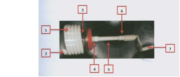
Figure 2 shows the complete assembly looks of the
model of the prototype design. The model being assemble
using PVC glue and can be dismantle easily without
creating any damage to the design.
This model of prototype design then immediately
tested at different lift angles: 0
°
to 40°
in a containercontaining water. As the handle of the discharge pipe was
rotate manually using hand, the one third of plastic
container easily submerged. As the drum rotates at
constant manual speed, it collects both water and air
repeatedly. The pocket of water becomes compressed and
manometric pressure was set up. Based on the data taken
during the testing, the model of prototype worked best at
lift angle of 15-25°. Then the actual prototype of the
design was started to fabricate.
Figure 1 Model of Prototype to understand the pumping action of the pump.
2.2 Fabrication of the prototype
Since the size of the prototype was relative big and
long, hence the fabrication process was divided into
several categories i.e. fabrication of cylindrical drum with
steel frames (Figure 2), fabrication of support, fabrication
of coiled tube, fabrication of aluminum pipe with rotating
handle, fabrication of guide and assemble the pump.
In the fabrication of cylindrical drum, a 38 mm hole
was drilled by using hole-saw at centered top surface of
the drum. This hole was used for water outlet. Another
hole was drilled at the bottom edge of the drum for water
inlet. Moreover, there should be an easy access to coil the
tube inside the drum, therefore the top and bottom
surfaces of the drum were cut by using electrical jig-saw.
The eight holes were then drilled using hand drill
machine around the top edge of the circumference of the
drum. A complete view of the pump is shown in Figure 3.
Mild steel material frame was used to attach the
drum with the discharge pipe so that drum should rotate
as rigid body with the drum. A 25.5 mm metal strip was
cut using cutting machine. This strip was rolled by using
rolling machine to ensure that it secured around the
circumference of the drum. The drum would easily
produce wear and tear when more loads are applied to the
drum as it is made of plastic. Hence, the strip was Figure 2 Illustrate the design of the prototype
(1-Mild steel pipe, 2-Angle iron bar, 3-Mild steel metal strip, 4-Plastic drum, 5-Aluminium pipe, 6-Hole for water discharge, 7-Bolt and nut, 8-Water Inlet opening.)
Figure 3 Major components of the pump
84 December, 2016 AgricEngInt: CIGR Journal Open access at http://www.cigrjournal.org Vol. 18, No.4
designed to easily reassemble and dismantle from the
drum. A draw catch was used to join the end connections
of the strip. Eight holes were then drilled using drill
machine along the strip. Furthermore, 25.5 mm angle iron
bar was then cut into four pieces which was used to
connect the strip with 51 mm shaft. The angle iron bar
needed to be bent to follow the diameter of the shaft.
Then the angle iron bars were welded by using arc
welding and MIG welding machine.
A ten meter long flexible plastic tube was coiled
inside the drum. The cable ties were used to tighten the
tube around the wall of the drum. Any holes on the drum
were covered using epoxy glue to ensure no water leaked
into the drum. Two sockets were used for the inlet and
outlet to ensure that the tube was in placed when rotating
the drum.
Aluminum pipe was cut using cutting machine to
five meters. Water outlet was drilled using milling
machine at the aluminum pipe. High temperature sealant
was applied just above the water outlet to prevent the
water flow up to the handle. A 25.4 mm PVC pipe was
connected to the end of the aluminum pipe by using rivet.
This PVC pipe was shaped into L-shaped.
For assembling the pump, first the metal strip was
tightened to the drum using draw catch, then eight pieces
of bolt and nuts were used to fasten the support to the
drum. One end of the aluminum pipe was inserted into
the steel shaft and secured it using epoxy glue. The tube
was then tightened by using hose clamp to the aluminum
pipe.
3 Results and discussion
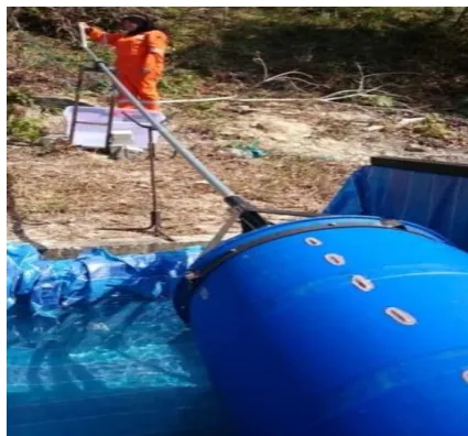
The pump was tested (Figure 4) after the fabrication
and assembly process were completed. There was an
open area at the back of the UTB’s workshop and also a
small hill that was suitable to carry out the test. A
manmade pool was made for this testing. The test was
carried out to determine the amount of water flow at
different angles. Note that the angle of the hill itself was
already at angle 15, therefore the initial test was at angle
15.
Tables 1-3 show the result of the operation of the
pump at angles 15, 20 and 25 degrees, respectively. If the
angles of inclination of the discharge pipe with the
horizontal surface were more or less than 15-25 degrees,
then the pumping action of the coiled tube pump was
reduced as a result discharge reduced drastically. So the
optimum angle of operation was found to be within 15-25
degrees.
Figure 4 A set up to carry out the testing
Table 1 Water discharged at an angle of 15 degrees
No
Time, t
s No. of turn, n
Total discharge Discharge,
Q
x 10-4 (m3 s-1)
Speed, N r/min
x 10-3 (m3) Liter,
L
1 300 130 28.90 28.90 0.963 26
2 300 135 44.795 44.795 1.493 27
3 300 133 40.460 40.460 1.344 26
Tables 1-3 show that more water was collected when
the angle of operation was 20 and less water collected at
angle of operation 15. At angle 15, since it was almost
horizontal to the water level, less water was collected due
the water inlet had less contact with the water. The speed
at angle 15 was faster than the other two angles.
However, when the angle was at 25, the water did not
flow continuously because the water inside the coiled
tube faced difficulty to move up to the water outlet. The
highest discharge was obtained at angle of operation of
20 degrees.
The water power pumping in the inlet (input) and
outlet (output) were calculated to determine the human
power that was used and compared them with given
average maximum human power. The pump efficiency
was based on 5 minutes of rotation only. Basunia and
Gee-Clough (1999) mentioned that the efficiency could
be 50%-60% at lower speed range. The efficiency
calculated in this project however was within 10%-21.6%.
The efficiency of the present design could be raised by
further improvement using relatively large diameter
reinforced plastic pipe for making the coil. However,
when the testing was carried out, few limitations on the
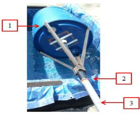
design had been discovered as shown in Figure 5 below.
At point 1, bolt and nut was used to connect the support
and the drum. Since the weight of the drum was heavier
and it was made of plastic, it may create wear and tear to
the drum. At point 2, epoxy glue was used to secure the
aluminum pipe to the support. However the epoxy glue
may easily break when more force is applied to the pump.
At point 3, as aluminum pipe has low modulus of rigidity,
it bents when rotating the pump even though two supports
were applied along the aluminum pipe. Table 2 Water discharged at an angle of 20 degrees
No
Time, t
s No. of turn, n
Total discharge Discharge, Q
x 10-4 (m3 s-1) Speed, N
r/min
x 10-3 (m3) Liter,
L
1 300 120 46.240 46.240 1.541 24.2
2 300 123 57.800 57.800 1.927 25.0
3 300 127 62.135 62.135 2.072 24.6
Average 300 123 55.317 55.317 1.847 24.63
Table 3 Water discharged at an angle of 25 degrees
No
Time, t
s No. of turn, n
Total discharge Discharge, Q
x 10-4 (m3 s-1) Speed, N
r/min
x 10-3 (m3) Liter,
L
1 300 121 34.68 34.68 1.156 24.0
2 300 125 46.24 46.24 1.541 24.5
3 300 123 49.91 49.91 1.664 25.4
Average 300 123 43.61 43.61 1.454 24.7
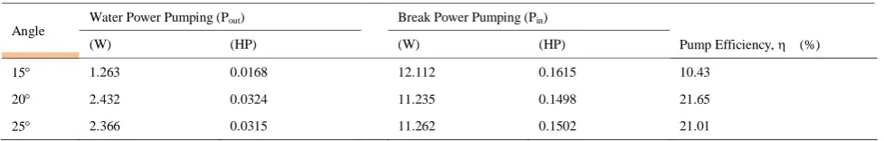
Table 4 Power in pumping and pump efficiency at different angle
Angle
Water Power Pumping (Pout) Break Power Pumping (Pin)
(W) (HP) (W) (HP) Pump Efficiency, (%)
15 1.263 0.0168 12.112 0.1615 10.43
20 2.432 0.0324 11.235 0.1498 21.65
86 December, 2016 AgricEngInt: CIGR Journal Open access at http://www.cigrjournal.org Vol. 18, No.4
Figure 5 Critical analysis of the pump
(1-Metalic frames attaching with drum, 2-Connection of metallic frames with discharge pipe, 3- Rotating shaft)
4 Conclusions
Some difficulties were occurred during the
construction of this coiled tube using plastic drum as coil
supporting structure. It the critical analysis the rust
formation was observed at the connection of the metal
strip and angle iron bars because that areas were
continuously in contact with water. As the connection of
the support and aluminum pipe was secured by epoxy
glue only, when there was more force applied during the
rotation, the glue might easily break due to greater torsion
in between the connections.
Furthermore, the maximum human power that a
person can handle in a day is around 75 W. During the
testing, only approximately 12 W of human power was
used which was around 16% of human power. However,
human power of a woman and a man is different. For this
test, the manual power was calculated based on the power
availability of a woman to rotate the pump.
The advantages of this internally coiled tube pump
are that the coiled tube was secured from sharp or foreign
object since it was inside the drum and also the coiled
tube would never misalignment. Since the diameter of the
tube is 38 mm, larger size of tube diameter will give more
water flow than collected. As the design of this pump is
simple and the material used is easy to get, less
maintenance is needed except for the bearing itself.
However, in term of manufacturing, it was little bit
difficult to assemble or coil the tube inside the drum. So it
can be assembled outer circumference of the drum
The purpose of this project was to collect more
water flow in less time. From this experiment, the
average amount of water flow collected was
approximately 9.0 liters per minute. Hence, the expected
daily usage for the water flow collected would be
approximately around 500 liters per hour. The manual
operation of the pump was relatively easy because the
working mechanism was just by rotating the
half-submerged drum in water.
Acknowledgments
The authors are very grateful to the Universiti
Teknologi Brunei (UTB) for financial support and allow
us to complete the project in the departmental workshop
of the University.
References
Basunia, M. A., D. J. Hilton, and S. Ahmed. 1992. The manually operated coiled tube pump: a new design, Bangladesh Journal of Agricultural Research, 17(2):133-141.
Basunia, M. A., and D. Gee-Clough. 1999. Performance evaluation of a manually operated inclined axis coiled tube pump. Agricultural Mechanization in Asia, Africa and Latin America, 30(4):44-49.
Morgan, P. R. 1979. A new water pump: spiral tube, Zimbabwe Science News, 13(18):179-180.
Mortimer, G. H., and R. Annable. 1984. The Coil tube Theory and Practice. Journal of Hydraulic Research, 22(1):9-22.
Reimer, M. 1986. The stream – driven coil pump, Waterlines, 5(1):13-19.