Vol.9 (2019) No. 6
ISSN: 2088-5334
Identify the Object’s Shape using Augmented Reality Marker-based
Technique.
Charlee Kaewrat
#1, Poonpong Boonbrahm
#2 #School of Informatics, Walailak University, 222 Thasala, Nakhon sri thammarat, 80160, Thailand E-mail: [email protected], [email protected]
Abstract— At present, new technology affects daily life in both direct and indirect ways. Internet technology can connect people
around the world through social networks. It can facilitate online shopping or e-commerce, which is the popular culture of today business. Contents provided in the online shopping must be in the form that customer can interact with, i.e., it must be converted from analog data to digital information. For apparel or clothing business, only picture and information of the dresses, such as size, color, etc., may not be enough, since the customer did not know whether it will fit their bodies or not. To make sure that the dress they wanted to buy fit their body, the body size of the customers must be known. With the known body size, generating the 3D model of the customer to try on the 3D virtual model of the dress is possible, and the decision to buy is possible. There are many ways to find the exact body size and generate a 3D model of the customers i.e. using 3D scanner, using Photogrammetry technique (merging many photographs of the customers’ bodies to create the 3d model) or generating 3D model with known information using 3d computer graphic software such as Autodesk Maya, 3D max. The techniques mentioned above have some drawback because it required either an expensive device or expert to create a 3D model which may take a long time. Therefore in this research, we present the technique using marker-based Augmented Reality to acquire the shape of the objects. By wrapping the markers around the surface of the object that we want to measure, each marker’s position can be identified, and when combined, the shape and sizes of the object can be created. This technique takes a shorter time than other method and does not require any sophisticated device but still give good results. We separate the experiment into three groups, group one, testing the concept with five objects with different sizes and shapes with one row markers and group two, testing cylindrical objects with four row markers, and group three, testing with a mannequin to find the shape of human’s body. we have found that the shape and size of the objects that we have created are very close to the real one with the maximum error of less than 5%. It possible to generate the whole 3D object which can be adjusted to support virtual fitting room.
Keywords— augmented reality; marker-base technique; measurement.
I. INTRODUCTION
At present, the advancement in digital technologies, not only create many innovations for supporting the facilities in humans’ daily life but also change the way we live and do business. It connects people around the world by social media through devices such as computer and smartphone. These digital transformations have changed the real world into the digital world. The conversion from hardcopy or photo to digital files are some of the examples. Process in doing business is also changed by this transformation, as can be seen in e-commerce and e-marketing. With the popularity of e-business, almost everything is available for buying online, and one of the top five that are selling well is clothing. For selling on the internet, a seller has to post a product’s details. The basic way for presenting a product is showing the 2D picture of the product, and specify a size to make a buyer understand the real size of a product. Usually,
measuring tape. Besides that, the VFR can display the virtual cloth superimposed on a real body making it possible for the user to see how they look with the clothes that they have selected, which will certainly improve buyer’s confidence before buying it. With the Kinect, the only 2D image of the cloths will superimpose on the body image. If we can have a 3D model of the virtual cloth, then the buyer can see how the virtual clothes fit them even when they move. There are three popular methods for identifying an object’s shape and create a 3d model, i.e., using a 3D scanner, using photogrammetry technique and using 3d computer graphic applications. For 3D Scanner, the device uses a laser signal or infrared signal for detecting the object. When the released signal impact on the surface of an object, it reflects the signal back which from the calculation, can tell the position of the surface, and then the system will generate the 3d model that replicates the real one. At this time, the device is expensive, so it is not practical for use. For photogrammetry, this technique uses many photos of an object in several views and then merged all photo to 3d model using the software such as Autodesk Recap. The quality of the 3D object depends on how well the photo has been taken. This method takes a long time for processing, not to mention the time spent on taking the picture and for the last method, Using 3D computer graphics applications such as Autodesk Maya, 3D Max, or Blender for creating 3D models, textures, layout, and animations. With this technique, the quality of the model depends on the skill of the creator. If the creator is an expert with skills for modeling, the result will be great. In contrast, if the creator is the beginner, the result may not be acceptable.
According to the three methods, some may have the advantages than others, but the technique is the same, i.e., detecting the surface’s position of a real object and combine all the positions to form the object. In this paper, we will present a new way to get the data for generating the 3D object using Augmented Reality (AR). The advantage of Augmented Reality (AR) is that it can track the position and display contents on that position in the real world. There are two techniques for tracking, i.e., marker-based AR technique and Marker-less AR technique. In a marker-based AR application the images (or 3D model, text, sound or others) to be recognized are provided beforehand while in the Marker-less technique, the application recognizes things that were not directly provided to the application beforehand. In this research, the marker-based technique was required for identifying the shape and size of a real object.
From studies of other people's research. Using the 3D scanner is a great way to get the 3D model because while capturing the surface and textures, it can create the mesh in real-time. The working process of the 3D scanner is related to the reflection of light from the object’s surface. So the factor that dominates the success of the scanning process is how the light reacts to the surface of the objects. For example, if the object is black, then it will absorb the light, and no reflection of light from the surface could not be detected. In that case, the model is not perfect. To solve this problem, some researchers [3] used algorithms to fix the problem and make the perfect 3D model. Although the 3D scanner is a perfect tool for making a 3D model, it is still expensive. An alternative way is using the Microsoft Kinect
which use the reflected infrared light to create a 3D model. The infrared light that reflected the object’s surface will create the depth image which can tell the position and shape of an object. The working concept of this device is the same as the 3D scanner excepted that there is some limitation in term of the quality which depended on the distance. If the object is far away from the Kinect, then the shape of the object is not good. Due to this limitation, using multiple Kinects to extend the detecting areas is possible as can be seen by using this concept in scanning the human body [1] and [10]. In [8], the researchers use two Kinects to capture the upper’s body and lower body. The cameras from these two Kinects captures the body in the same direction while the third one captures the backside in the opposite direction. The Kinect's position is around the user to capture the whole body with the distance between the user and the Kinects about 2 meters. When the user rotates, the Kinects will capture the part of the body and merging all data to generate the 3D model of the whole human body. [2] used multiple Kinects to separate the human body from the background and to generate a 3D model for real-time displays. In [5] also use one Kinect for capturing the rotating object. By extracting the objects from the background, the results are acceptable. Results from [6], [9], [11], and [12] also confirm the same result.
Although Kinect can make a 3D model and real-time tracking, it is necessary to connect with the computer for processing the data, so the high-performance computer is required for processing speed. Since the depth image feature in the Kinect, making it possible to track an object’s position and identify an object from the background, so many companies had developed devices to support these features. The one that has the same features as the Kinect is the Depth camera. It is smaller than Microsoft Kinect, and it can real-time tracking. In [14] and [4] used the Depth camera to makes a 3D model which have a convex shape or depth just like the real object.
At present, both the Kinect and Depth camera are not commonly used. On the other hand, the general device that everybody has access to is the webcam and the smartphone, which also have a digital camera. With software, this camera can create a 3D model as well. Using a computer with a webcam, the result from the process of it is 2d images. If using to identify the shape and size of an object have to use another technique together, to analysis an object’s position and extracting it from the background. In research [7] and in research [13] used a dual digital camera by Dense stereo technique to combines the photos from the left camera with the photos from the right camera, the result form technique make 3d model without using the computer. Using the smartphone to capture the pictures around the object and then import these data to a program, such as Adobe recap or Autodesk 123D Catch, all the pictures will be merged to generate the 3D model. In this research, we present the new technique to identify the shape and size of an object by using a smartphone with a marker-based Augmented reality technique.
II. MATERIAL AND METHODS
sound, video, text, etc., superimposed on the real environment using computer or smartphone process. The point of view depends on the device position. So, to improve the user’s experience, there are two components to be considered, i.e., detection part and display part. In the detection part, there are two ways for position tracking, either by using a marker-based technique which requires physical symbol such as a picture or signed board or marker-less technique in which the position of the digital model can be found from the environment such as GPS. For the display part, the digital content will display at the position given by the code from the marker or the GPS.
In this research, we will focus on marker-based technique because it can give precise data without any distortion by the environment. Today, there are many tools available for designing and developing the AR system such as Vuforia, ARKit, ARCore, OpenCV library, etc. These libraries have the same processing algorithms. From the literature review, we have found that the OpenCV library has an ArUco function which is more flexible in term of the marker’s size and the number of markers set available to use. The structure of these markers is a black square with a small white square within it. Figure 1 shows the small white square in each marker which has different positions for identifying a marker’s number. The process of ArUco begins with the detection of the black square and then make a grid for separating a white square’s position. Comparing the position of the white square with the database, ID, or number of the marker can be identified.
When the AR tracking system found markers, it knew the position where the virtual world will be located in the real world and also what function to be operated at that position. With the Unity 3D game engine, any multimedia or game can be created in the virtual world at the position verified by the marker. Since a scene in Unity3D has a direction the same as a real-world, i.e., X-axis is a width (Horizon), Y-axis is a height (vertical), and Z-Y-axis is a depth, then moving or rotating the camera around the markers, the new position can be calculated. In this experiment, we would like to get the size and shape of the object, then finding the position of each marker wrapping around the object, the shape of the object can be calculated. Using the AR technique with Virtual world, the conceptual framework of the experiment are as follows :
Fig. 1 Diagram of the conceptual framework
A. Hardware, software and markers
In this research, the hardware and software used are as follows:
Hardware
We were using MacBook Pro with Webcam (Logitech brio) and all of the experiments in the laboratory. And set the webcam with a webcam tripod for fix the position between the objects and webcam. When the capture process, we set an object on the Potter’s wheel, it is easy to rotate an object.
For the hardware setup, we use the Logitech Brio webcam for capturing the image of the object. The Logitech BRIO is the ultra HD webcam with the wide 90 degrees capturing angle which also supports video capturing at 1080p at 60fps and 720p at 60fps. The output from the webcam was sent to the MacBook Pro with 2.2GHz 6-core Intel Core i7 and 256 GB RAM for processing. The webcam was placed on the tripod at the fixed distance from the object which is sitting on the Potter’s wheel for easy rotation.
Software
We have selected OpenCV (Open source computer vision library) for creating the markers because it supports many platforms such as iOS, Mac os, Window, Linux. Written in C/C++. OpenCV has many features for supporting our work, and one of them is ArUco feature. This feature is based on finding the similarity between 2D image projection and points in the real world. For creating a game or multimedia content, the Unity 3D game engine was selected since it can be used to create an application in a smartphone and other platforms, i.e., OS window, OS X. Moreover, with the features of the Unity3d engine, the virtual world of 3D space can be created easily.
Markers
In this setup, the 2D image were used as the markers. The markers should be flexible because an object’s shape has curves. The structure of the markers is the black square, with many small white squares within it. As shown in figure 2, to differentiate the markers and identify each of them, the small white squares in each marker are located at different positions. The process of ArUco begins with detecting the black square and then make a grid for separate a white square’s position and then using that position to compare with the marker’s number in a database to identify the marker’s number.
Fig. 2 ArUco Markers.
B. Experiment setup
using marker-based AR technology. Since we would like to measure all the position around the object (i.e., x and y-axis), so we need a series of marker to wrap around the object. While the system detected markers, it will identify a position of the first marker and then with the rotation. We will get the position of the next one and so on. By setting the reference point, we can get the series of the positions which then can form the cross-section of the object.
The purpose of this research is to identify the size and shape of objects by using the marker-base technique. In this experiment, a series of markers were used for this purpose. By wrapping the series of marker around the objects, the shape and size of the object in two dimensions can be calculated and display. We separate the experiment into three groups, group one, testing the concept with five objects with different sizes and shapes with one-row markers and group two, testing cylindrical objects with four-row markers, and group three, testing with a mannequin to find the shape of human’s body. According to the conceptual framework, this section explains all step as follows:
Fig. 3 The marker series on the real object.
Step 1 Wraps an object with markers.
Since the objects have a different size and shape, so we set the appropriate makers size to wrap around them on the object surface. A series of sequential markers have the same pattern, which always starts with marker id 1, and 2 and 3 continue to last the last one, as shown in figure 3. We make marker series to the row which all marker in that row has the same size and same space between markers. When wrapping the markers on an object’ surface, last marker and first marker have come together like a circle. In this research, we have experimented with three groups as follows:
Group one: Regular shape with a one-row marker. A: Cube shape has a size of 3.5x3.5x.35 cm. The circumference is 14 cm.
B: Cuboid shape has size 14.5x 21.5x 4.4 cm. The circumference is 72 cm.
C: Cylinder shape has a circumference of 33.5 cm. D: Ellipses shape no.1 has a circumference’s size of 24 cm.
E: Ellipses shape no.2 has a circumference of 53 cm. Group two: Cylindrical shape with 4-row markers, to prove our technique can generate the whole surface of the object’s shape.
F: Cylinder shape no.1 has a circumference of 32.3 cm and 10 cm. for the object’s height.
G: Cylinder shape no.2 has a circumference of 15.7 cm and 10.5 cm. for the object’s height.
Group three: body shape, usually, a circumference of waist and chest use to identify shirt’s size.
H: The mannequin shape has 65 cm. for waist size and 87 cm. for chest size.
Step 2 Collects the marker’s point.
In order to get the cross-section of the object, each point on the circumference must be calculated from the position of the markers that connected. Even though each position (x, y, and z ) of the marker can be identified using AR technology, but to get all the positions that formed the circumference, those positions must have the same reference point. To set the reference point, we have to start from one marker as the starting point, and the next marker’s position will refer to that position and so on. With this concept, each time we capture the markers, we have to capture two markers. The first marker must be the second marker from the last capture, which will be used as a related reference point. This way, all the markers’ positions will be related to each other and to the first marker, i.e. the reference point. When the system tracks the markers, it will get the markers id, position, and rotation and keep them in the database. With this technique, the database will have the duplication of the data of the markers For example: if the number of markers that wrapped around the object is four, then the data of all the markers in the database will be like this:
Object A = {(ID1, ID2), (ID2, ID3), (ID3, ID4), (ID4, ID1)}
Where ID is the index of markers. Step 3 Generate the marker’s point.
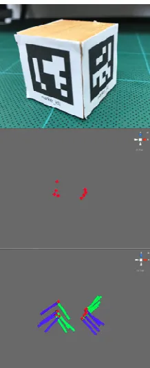
This step deal with reading all the data and generated a markers’ positions from the first marker to the last one. The result is the position of all the markers that wrapped around the object, as shown in Figure 4. From the figure (Fig. 4 ), we have found that some of the marker’s position is quite closed. This is due to the fact that the rate of capturing is not constant.
Since we cannot capture all the markers at the same time, so each time, only two markers were captured as mentioned before. After we captured all the markers that wrap around the object, we have to align all of them into the correct positions to form the cross-section of the object. In our experiment, only the first marker is in the right position, and the rest is not. Because, every time we capture the markers, either we have to rotate the camera or fix the camera and rotate the object, which in this case, we choose the second option. In our experiment, each time that we captured the markers, we got only the distance between the two markers that we capture and how they related to the first marker which we consider as the reference point. Since all the position of the marker can be represented as the vector, so each marker can be represented as the matrix-vector as in Figure 5.
Fig. 5 The vector in the matrix
Step 4 Classify the layer’s marker.
We create the layer’s marker method to separate marker in each row, especial the group two, which there are four markers row wraps on the objects. To classify, we only use vector Y (position in vertical) of marker position to find a position between each row. Therefore in the real situation, vector Y values of each row may not be the same values. So, to increase accuracy, we set up the distance in each row. We set marker id 1 as the first row, and compare with vector Y of another row. If the distance is closer, then we can identify as the same row. On the other hand, if vector Y is far apart, then the system will specify the marker is in another row. Which will repeat until the last one. Figure 6 show an example of layer markers.
Fig. 6 Cylindrical shape with 4-row markers
Step 5 Marker’s rotation
This step to determined marker’s rotation, which uses for rotate markers on the same row only. When we rotate and capture the next two markers, the rotation of the next two markers can be represented by the rotation matrix as in figure 7.
Fig. 7 The vector rotation in the matrix
The angle that the markers rotate, which define as Theta, is related to the numbers of markers used to cover the whole circumference of the object and can be calculated from the formula in figure 8.
Fig. 8 Formula for calculating a degree of angles
For example, if we have ten markers to cover the circumference of the object, we have to capture ten times because each time we have to capture the last marker too, as mentioned previously. Then the rotation angles that we have to concern is 360/10, which equal to thirty-six degree. This rotation angle will be on the y-axis of the markers, which is the markers’ plane, so it will make the x-axis to rotate. Step 6 Place the markers in the position.
In this step, the duplicated markers will be placed into the same position, by rotating them around the rotation axis (y-axis), using the formula in figure 9.
Fig 9 Formula for calculating a new marker’s position
Results can be seen in figure 10, where the green stick came closer to each other and then stack on each other.
Step 7 Distance calculation.
We cannot calculate the length of the circumference of the object by just using the position of the last marker and subtract the position of the marker because after putting the markers around the object, the position of the last marker will be very close to the first one. To solve this problem, there are a few steps to be done.
1) Calculate distance between markers: we calculate the circumference of the object by calculating the distance of the double markers starting with marker#1 and #2, then #2 and # 3 and so on until the last marker and marker #1. Example of this method is shown in figure 11, and the equation for solving this problem is shown in figure 12.
Fig. 11 For example to calculate a distance between markers (blue square is marker)
Fig. 12 The formula for calculates distances.
D = distance, x = vector x, y = vector y & z = vector z. 2) Calculate circumference: Summation of the total distance for the circumference of the object is done using the equation in figure 13.
Fig. 13 Formula for calculate circumference.
D is distance, x is vector x, y is vector y, and z is vector z. The convert the distance into centimeter, using the equation in figure 14.
Fig. 14 Conversion formula for the circumference
Cro = Circumference of the real object and C = Circumference
3) Calculate the object’s height: To identify the object height by calculating the distance between the top row with the bottom row.
C. Experiment
To prove that our method can identify the object’s size and can simulate a shape like real objects. We set up the experiment followed all step above with several objects which have different size and shape shown in figure 15, 16, and 17 as follows:
Fig. 15 Group one, Regular shape with one row marker.
Fig 16 Group two: Cylindrical shape with 4-row markers.
Fig. 17 Group three: body shape
III.RESULTS AND DISCUSSION
Fig. 18 An experiment result: Cross-section of the objects A
Fig. 19 experiment result: Cross-section of the objects B
Fig. 20 An experiment result: Cross-section of the objects C
Fig. 21 An experiment result: Cross-section of the objects D
Fig. 22 An experiment result: Cross-section of the objects E
Fig. 23 An experiment result: Shape of the objects F and G on the front view
Fig. 23 An experiment result: Shape of the objects F and G on the perspective view
Fig. 24 The real shape of the objects Fand G
Fig. 25 An experiment result: Shape of the mannequin on the front view.
Fig. 27 Real shapes of the mannequin.
TABLE I
GROUP 1, AN AVERAGE VALUE FROM THE CALCULATE EXPERIMENT.
Object Real size (cm.) Experiment results (Avg.)
Error
A 14 13.91 0.64%
B 72 72.42 0.58%
C 33.5 33.64 0.42%
D 24 23.8 0.83%
E 27.5 27.02 1.75%
TABLE II
GROUP 2, AN AVERAGE VALUE FROM THE CALCULATE EXPERIMENT.
Object RH RC EH EC ErH ErC
F 10.5 33.5 10 32 4.76% 4.47%
G 16 22 16.3 23.01 1.87% 4.95%
RH is Real size: Height RC is Real size: Circumference EH is Experiment results: Height
EC is Experiment results: Circumferences ErH is Error: Height
ErC is Error: Circumference
TABLE III
GROUP 3, AN AVERAGE VALUE FROM THE CALCULATE EXPERIMENT.
Object : H
Real size: Circumference
Experiment results (Avg.)
(cm.)
Error
Chest 65 67.74 4.21%
Waist 87 88.41 1.62%
IV.CONCLUSION
Using our technique with several different types of objects, it can identify the shape and size of objects. From the experiment result, the shape from the system looks similar to the real objects, while the size of the objects from the calculation is very close to the real object with the maximum error of less than 5%. Using our marker-based AR technique takes a much shorter time and did not need sophisticated devices but still get a good result. Moreover, it can be used with the smartphone as well. And can be adapted to support the virtual fitting room for identifying a body’s shape without using the measuring tape. Another advantage over measuring tape is that our technique can identify a convex and concave of the human’s body while the measuring tape cannot.
ACKNOWLEDGMENT
This research was financially supported by Walailak University, Nakhon si Thammarat, Thailand. In contract no. 05/2561.
REFERENCES
[1] Adikari, A. M. S. B., N. G. C. Ganegoda, and W. K. I. L. Wanniarachchi. "Non-contact human body parameter measurement based on Kinect sensor." IOSR Journal of Computer Engineering 19.3 (2017): 80-85.
[2] Alexiadis, Dimitrios S., Dimitrios Zarpalas, and Petros Daras. “Real-time, full 3-D reconstruction of moving foreground objects from multiple consumer depth cameras”. in IEEE Transactions on
Multimedia 15.2, pages 339-358, 2012.
[3] Allen, B., Curless, B., & Popović, Z. “The space of human body shapes: reconstruction and parameterization from range scans.” In ACM transactions on graphics Vol. 22, No. 3, pages. 587-594. ACM, July 2003.
[4] Lee, Kyoung-Rok, and Truong Nguyen. "Realistic surface geometry reconstruction using a hand-held RGB-D camera." Machine Vision
and Applications 27.3 (2016): 377-385.
[5] Newcombe, Richard A., et al. "KinectFusion: Real-time dense surface mapping and tracking." 2011 IEEE International Symposium on Mixed and Augmented Reality. IEEE, 2011.
[6] Nguyen, Chuong V., Shahram Izadi, and David Lovell. "Modeling kinect sensor noise for improved 3d reconstruction and tracking." 2012 second international conference on 3D imaging, modeling, processing, visualization & transmission. IEEE, 2012.
[7] Se, Stephen, and Piotr Jasiobedzki. "Photo-realistic 3D model reconstruction." Proceedings 2006 IEEE International Conference on Robotics and Automation, 2006. ICRA 2006. IEEE, 2006.
[8] Tong, J., Zhou, J., Liu, L., Pan, Z., & Yan, H. “Scanning 3d full human bodies using kinects”. IEEE transactions on visualization and
computer graphics, 18(4), 643-650. 2012.
[9] Xu, Di, et al. "Kinect-based easy 3d object reconstruction." Pacific-Rim Conference on Multimedia. Springer, Berlin, Heidelberg, 2012. [10] Yoshino, Naoyuki, Stephen Karungaru, and Kenji Terada. "Body
Physical Measurement Using Kinect for Vitual Dressing Room." 2017 6th IIAI International Congress on Advanced Applied
Informatics (IIAI-AAI). IEEE, 2017.
[11] Yousef, Khalil M. Ahmad, Bassam J. Mohd, and AL-Omari Malak. "Kinect-Based Virtual Try-on System: A Case Study." 2019 IEEE
Jordan International Joint Conference on Electrical Engineering and Information Technology (JEEIT). IEEE, 2019.
[12] Yu, Tao, et al. "Doublefusion: Real-time capture of human performances with inner body shapes from a single depth sensor." Proceedings of the IEEE Conference on Computer Vision and Pattern Recognition. 2018.
[13] Yun, SangUn, Dongbo Min, and Kwanghoon Sohn. "3D scene reconstruction system with hand-held stereo cameras." 2007 3DTV Conference. IEEE, 2007.