Vol.7 (2017) No. 3
ISSN: 2088-5334
Formation Pattern Based on Modified Cell Decomposition Algorithm
Iswanto
#*, Oyas Wahyunggoro
#, Adha Imam Cahyadi
##
Department of Electrical Engineering and Information Technology, Universitas Gadjah Mada, Yogyakarta, Indonesia E-mail: [email protected]
*
Department of Electrical Engineering, Universitas Muhammadiyah Yogyakarta, Yogyakarta, Indonesia
Abstract— The purpose of this paper is to present the shortest path algorithm for Quadrotor to make a formation quickly and avoid
obstacles in an unknown area. There are three algorithms proposed in this paper namely; fuzzy, cell decomposition, and potential field algorithms. Cell decomposition algorithm is an algorithm derived from graph theory used to create maps of robot formations. A Fuzzy algorithm is an artificial intelligence control algorithm used for robot navigation. The merger of these two algorithms is not able to form an optimum formation because some Quadrotors which have been hovering should wait for the other Quadrotors which are unable to find the shortest distance to reach the formation quickly. The problem is that the longer time the multi Quadrotors taking to make a formation, the more energy they use. It can be overcome by adding potential field algorithm. The algorithm is used to give values of weight to the path planning taken by the Quadrotors. The proposed algorithms show that multi Quadrotors can quickly make a formation because they can avoid various obstacles and find the shortest path so that the time required to get to the goal position is fast.
Keywords— multi-quadrotor; fuzzy; formation pattern; cell decomposition
I. INTRODUCTION
Multiple Quadrotors are a set of centrally controlled Quadrotor cooperating to carry out a work [1]. To form a formation pattern, a UAV requires path planning algorithm such as of Teaching-Learning-Based Optimization (TLBO) algorithm presented under the inspiration of teaching and learning behavior in the classroom [2]. The algorithm is applied to design a path with search and distance angles, in which the higher the speed of the convergence, the better path, and the shorter route can be identified. Finally, the result of the comparative experiment shows that the TLBO algorithm is a feasible and effective method for UAV path planning applied in a static environment.
The other path planning algorithm such as the Pythagorean hodograph curve is used by Yi et al. for UAV path planning in a three-dimensional environment [3]. When a UAV detects an obstacle, the obstacle positions in the path are recalculated, and the path between the obstacles and the goal position is replanned. The algorithm will form Curvature Constraint and Torsion constraint for the Quadrotor to be able to avoid obstacles and reach the goal in a static environment.
A graph-search algorithm such as the two-way D* (TWD*) algorithm is used by Dakulovi & Petrovi for path planning [4]. The algorithm is a merge of D* algorithm and
Witkowski's algorithm that creates a new algorithm for path planning. Witkowski's algorithm uses two processes namely forward and backward process to be used in search algorithms. In the trial, the algorithm can identify the shortest path in a static environment.
A parallel algorithm for polygon building construction and graph theory are used by Sridharan & Priya for path planning in an unknown environment to be implemented in the FPGA that serves to connect the legs between components [5]. The study uses a parallel algorithm to detect the tip ends of obstacles by reconstructing the obstacles. With the algorithm, an electronic component environment is formed. Based on this, the visibility graph theory is used to create a path planning to avoid obstacles in the form of Polygon. The algorithm has been proven successfully in creating a path planning for a robot to move to the goal position and avoid obstacles. The algorithm is not applied in dynamic environments.
(CSG) algorithm is used to form the obstacle that has been detected by the sensor. Gaussian and median filters are used to filter noise on the sensor, and then the noise is filtered by the threshold to obtain the original image. The result of the simulation shows that the underwater path planning can move the robot to the goal position and avoid many obstacles.
Detecting and avoiding obstacles can be conducted by using the global method of path planning practiced by Wang et al. who used radar to detect obstacles in an unknown area [7]. Cell decomposition graph theory is used to create a map by dividing the environment into small grids, and then a few lines are used to connect the A* algorithm, and the fuzzy algorithm is used to create a path planning. In the experiments, the algorithm is proven to be able to avoid static obstacles.
From the researchers mentioned earlier, cell decomposition algorithm merged with fuzzy algorithm have been applied to dynamic environments, so that the algorithm can be applied to the formation pattern of Multi Quadrotor. The problem is that they are not able to find the shortest path. Therefore, the paper presents an algorithm to be added to give values of weight to the environment map that is potential field algorithm.
This study focuses on finding the shortest path to the formation of quadrotors in an unknown environment. By getting the shortest path, the formation can be made quickly. To get the shortest path, quadrotor gets some problems such as avoiding obstacles in the form of static or dynamic obstacles. The purpose of this study is to find the shortest path to the formation quickly presented in the research method in section II. In this section modeling agent, robot formations, environmental models, and path planning are described. The depiction of the analysis of the results of the study is described in Section III. The depiction of the conclusions of the analysis of this study is described in Section IV.
II. MATERIAL AND METHOD
This paper presents a Multi Quadrotor path planning for the robots to reach the goal and avoid obstacles with a global view by using fuzzy and cell decomposition algorithms. Research methods used in this paper are a modeling agent, generating a map, path planning for the robots, implementing algorithms and giving potential values on the map.
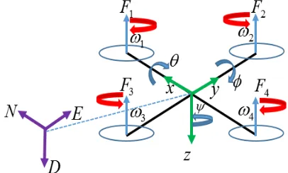
Fig. 1 Quadrotor modeling with a plus form belongs to peter corke
A. Agent Modelling
The agent used in this paper is rotary wing Quadrotor that is a type of UAV that uses the thrust of four motors placed at the end of a Quadrotor frame [8]. The Quadrotor used in this paper has the model of plus form belong to Peter Corke as shown in Fig.1 [9]. It shows that the Quadrotor can perform vertical take-off and landing which works by using four thrust obtained from four motors which have the same rotation speed [10].
By decreasing the speed of the motor
ω
1or by decreasingthe speed of the motor
ω
4, the Quadrotor moves forwardand backward. It decreases the motor speed
ω
2 to move tothe right and decreases the motor speed
ω
3 to move to the left [11]. The Quadrotor has twelve states consisting of six attitude states in which there are three states for Euler anglesnamely roll, pitch, yaw
[
]
T ψ θ φβ2 = and three states
for angular velocity namely
[
]
T ψ θ φβ4 = & & & . The six other
states are positions of
[
]
T z y x = 1β and the derivative
positions of the state
[
]
T m l k = 3β
[12], [13]. Based on thedescription mentioned above, the non-linear model of the Quadrotor used in this paper is as the following [11]:
k
x
&
=
(1)l
y
&
=
(2)m
z
&
=
(3)r
t
c
q
t
s
p
φθ φθφ
&
=
+
+
(4)r
s
q
c
φ φθ
&
=
−
(5)r
c
c
q
c
s
θ φ θ φψ
&
=
+
(6)(
c
φs
θc
ψs
φs
ψ)
T
m
k
&
=
−
1
+
(7)(
c
φs
θs
ψs
φc
ψ)
T
m
l
&
=
−
1
−
(8)( )
c
φc
ψT
m
g
m
&
=
−
1
(9)(
)
qr
db
p
x y z xΙ
Ι
−
Ι
−
−
−
+
Ι
=
2 4 2 1 2 3 22
ω
ω
ω
ω
&
(10)(
)
pr
y
db
q
y z xΙ
Ι
−
Ι
−
−
−
+
Ι
=
2 2 2 1 2 4 23
ω
ω
ω
ω
(
)
pq
k
r
z x y
z
Ι
Ι
−
Ι
−
−
−
+
Ι
=
23 2 1 2 4 2
2
ω
ω
ω
ω
&
(12)B. Robot Formation
Robot Formation is a collection of several robots cooperating to perform tasks. There are three robot agents presented in this paper so that to reach the goal position and avoid obstacles, a formation control for multi-robot path planning is necessary. A triangular formation in the multi-robot path planning as studied by Liu et al. by using a Euclidean distance of Cartesian coordinate vector algorithm to form the triangular formation applied to a wheeled robot controlled by the robot leader is needed [14].
This paper presents the V pattern formation formed by using the theory of Euclidean distance of Cartesian coordinate vector algorithm to form a robot formation pattern as shown in Fig. 2. It is seen that formation has an agent leader located in the middle of two agent followers. The distance between each Quadrotor is identical denoted as
D
, and the pattern orientation is denoted as thetaθ
.Fig. 2 V formation modeling
The position of the leader is (x, y, and z). The position of
the followers is
(
x ,
iLy
iL)
on the left side of the leader, and the position of the followers is(
x ,
iRy
iR)
on the right side of the leader for i = 1, 2, 3, n. The position equation for V formation for each of the agents:( )
1cos
θ
L i Li
y
iD
y
=
+
(13)( )
1sin
θ
L i Li
x
iD
x
=
+
(14)( )
2cos
θ
R i Ri
y
iD
y
=
+
(15)( )
1cos
θ
L i Li
y
iD
y
=
+
(16)Where
( )
x,
y
is the position of the robot leader,( )
θ
1 is the angle forming first branching to robot followerspositioned on the left side,
( )
θ
2 is the angle forming first branching to robot followers positioned on the right side, andR i L i D D
D= = is the distance between the followers to the leader.
C. Environment Modeling
Approximate Cell Decomposition is one of the methods in graph theory used by Katevas et al. to create a two-dimensional environment map by global sensing that divides the environment into small grids with identical size to create a path planning [15]. The path for the robots to move to the goal position and avoid obstacles is created by using the grids.
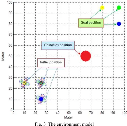
Fig. 3 The environment model
This study uses approximate cell decomposition algorithm to create a multi Quadrotor path planning map using a global view shown in Fig. 3 [16], [11]. It is seen that there are three robots forming a triangular formation in an unknown environment positioned in
(
x
R1,
y
R1)
,(
x
R2,
y
R2)
, and(
x
r3,
y
r3)
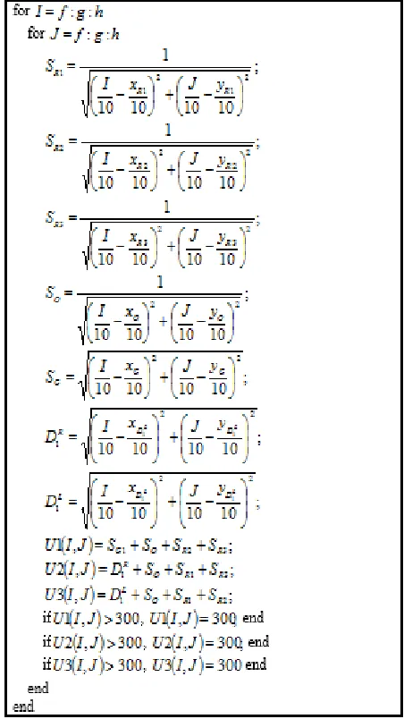
, there is a static obstacle in a position of (Xo, Yo) and there are three goal positions. By using these data, the environment map by using the source code as shown in Fig. 4 is obtained.Fig. 4 shows that
(
x
R1,
x
R1)
is the position of robot 1,(
x
R2,
x
R2)
is the position of robot 2,(
x
R3,
x
R3)
is the positionof robot 3,
(
X
G1,
Y
G1)
is the goal position of robot 1,(
XG2,YG2)
is the goal position of robot 2, and(
XG3,YG3)
is the goal position of robot 3. SG1 is the formula for the distance between the position of robot 1 and Goal 1,S
G2 is the formula for the distance between the position of robot 2 and goal 2, and SG3 is the formula for the distance between the position of the robot 3 and the goal 3.S
I1,
S
I2 is the distance between robot 3 and robot 1 and 2,S
I1,
S
I3 are thedistance between robot 2 and robot 1 and 3, and
S
I2,
S
I3 is the distance between the robot 1 and a robot 2 and 3, andO
robot and the obstacles.
R
G AndR
O are further summed up tobe a value for the environment matrix. Path Planning.
Fig. 4 Environment matrix formed by source code
Iswanto et al. have investigated the basic behavior of path planning using cell decomposition algorithm such as go-to-goal. [16] Implementing it to a Quadrotor. In this behavior, a robot is searching for the smallest value of the grid and following it to reach goal position. Cell decomposition
algorithm is a path planning algorithm in the
ℜ
2environment while Quadrotor position is in the
ℜ
3 environment. In the simulation, Quadrotor path planningused a fuzzy algorithm for
ℜ
2 environment position by giving a constant value at a certain height so that the Quadrotor was controlled by a reference value of grid spacing obtained from the fuzzy [17], [18], [19] algorithm. The algorithm has been modified by adding the potential [20] value on the cell decomposition grids as shown in Fig. 5.It is seen in Fig. Five that
k
R1 is the repulsion constantfor robot 1,
k
R2 is the repulsion constant for robot 2,k
R3is the repulsion constant for robot 3, and
k
O is the repulsionconstant for the static obstacle.
S
G1 Is the attractionconstant for the goal position of robot 1,
S
G2 is theattraction constant for the goal position of robot 2, and
S
G3is the attraction constant for the goal position of robot 3. Multi-robot Path Planning in this study uses the decentralized control in which each agent has a path planning algorithm with updated environment map which can renew the obstacle and the robot position data in real time as shown in Fig. 6.
Fig. 5 Environment matrix formed by source code
followers will be controlled decentralized to be able to avoid obstacles and find a path to get to the position of the leader
(a)
(b)
(c)
Fig. 6 Source code momentum matrix Ling Kung-an ROBOT 3
III.RESULTS AND DISCUSSION
In the experiment presented in this paper, Matlab is used as the software. By using Matlab, Quadrotor design modeling and algorithm design could be created, and the path planning algorithm could be simulated. Matrix environment has been created to simulate the robot type. There were two experiments conducted to assess the modified algorithms; the first experiments used a static obstacle and a dynamic obstacle and the second experiment used a static obstacle and a lot of dynamic obstacles. The simulation is to compare Modified Cell Decomposition Algorithm and Fuzzy Artificial Potential Field (FCDAPF) with Fuzzy algorithm cell decomposition.
(a)
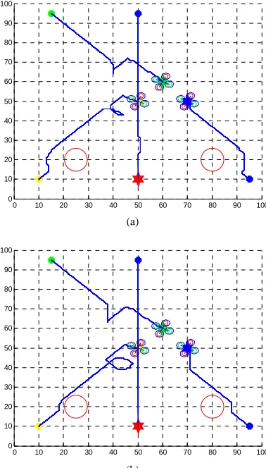
(b)
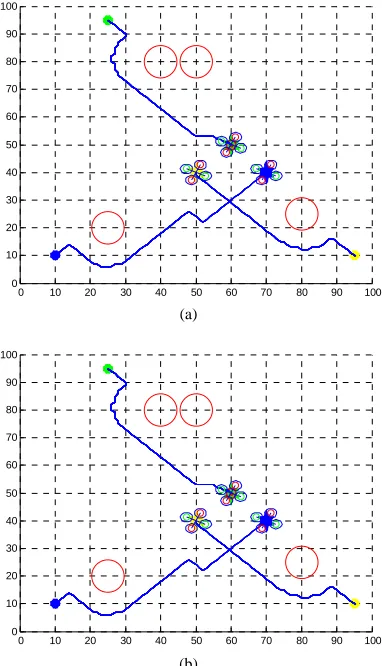
Fig. 7 Comparison FCD and FCDAPF algorithms in static environments
In the first experiment tested the algorithm in an unknown environment contained static obstacles like Fig. 7. The figure shows that the static obstacles located at the point (25.20) and point (80.20). While the starting point is at a point quadrotor (10,10) for quadrotor yellow, points (95, 10) for quadrotor blue and points (25.95) for quadrotor green color. There are three points of interest quadrotor that point (70.40) for quadrotor blue dot (50.40) for quadrotor yellow, and (50,50) for quadrotor colored green. Multi quadrotor will form a V formation with green quadrotor as leaders and others as followers. The environment was tested with two algorithms for the Fuzzy cell decomposition algorithm (FCD) shown in Fig. 7(a) and Fuzzy Potential Field Artificial cell decomposition in Fig. 7(b). From Fig. 7(a) shows that the multi quadrotor forms a pattern formation faster than in Fig.
0 10 20 30 40 50 60 70 80 90 100
0 10 20 30 40 50 60 70 80 90 100
0 10 20 30 40 50 60 70 80 90 100
7(b). This is because of multi quadrotor of Fig. 7(a) using a modified algorithm FCD, while multi quadrotor in Fig. 7(b) shows that the long form multi quadrotor pattern formation because they do not find the shortest path.
(a)
(b)
Fig. 8 Comparison of FCD and FCD modifications algorithms to form a V formation
In the second experiment, the algorithm is assessed in an unknown environment with four static obstacles as shown in Fig. 6. The figure shows that the static obstacles are located at the position of (25.20), (80.25), (50.80) and (40.80). The initial position for blue Quadrotor is (10, 10), for yellow Quadrotor is (95, 10), and for green Quadrotor is (25.95). The goal positions of the Quadrotor is (70.40) for blue Quadrotor, (50.40) for yellow Quadrotor and (50,50) for green Quadrotor. Multi Quadrotors form a V formation with green Quadrotor as the leader and the two others as the followers. The environment is assessed by using two algorithms that are the Fuzzy cell decomposition algorithm (FCD) as shown in Fig. 6(a) and Fuzzy Potential Field Artificial cell decomposition as shown in Fig. 6(b). Fig. 6(a) shows that the multi Quadrotors form a pattern formation more quickly than that shown in Fig. 6(b). This is because the former multi Quadrotors applies the modified algorithm FCD. The latter multi Quadrotors shows that they take a longer time to form the formation because they are not able to find the shortest path.
In the third experiment tested the algorithm in an unknown environment that there are two obstacles static and dynamic obstacles like Fig. 7. The figure shows that the static obstacles located at the point (25.20) and point (80.25)
and dynamic obstacles moving from the starting point (50.90) heading to point (50.10). While the starting point is at a point quadrotor (10,10) for quadrotor yellow, points (95, 10) for quadrotor blue and points (15.95) for quadrotor green color. There are three points of interest quadrotor that point (70.50) for quadrotor blue, points (50,50) for quadrotor yellow, and (60.60) for quadrotor colored green. Multi quadrotor will form a V formation with green quadrotor as leaders and others as followers. The environment was tested with two algorithms for the Fuzzy cell decomposition algorithm (FCD) shown in Fig. 8(a) and Fuzzy Potential Field Artificial cell decomposition in Fig. 8(b). From Fig. 8(a) shows that the multi quadrotor forms a pattern formation faster than in Fig. 7(b). This is because of multi quadrotor of Fig. 7(a) using a modified algorithm FCD, while multi quadrotor in Fig. 7(b) shows that the long form multi quadrotor pattern formation because they do not find the shortest path.
(a)
(b)
Fig. 9 Comparison FCD and FCDAPF algorithms in dynamic environments
IV.CONCLUSIONS
The paper presents an algorithm to form a robot formation pattern quickly by the modification of fuzzy cell decomposition algorithm. The cell decomposition algorithm is frequently used in robot path planning to create maps of unknown environments with a global view, while the fuzzy algorithm is frequently used in robot path planning for navigation using either the global or local view. By using the two algorithms, multi Quadrotors slowly form a pattern formation because the Quadrotors in a hover position will
0 10 20 30 40 50 60 70 80 90 100
0 10 20 30 40 50 60 70 80 90 100
0 10 20 30 40 50 60 70 80 90 100
0 10 20 30 40 50 60 70 80 90 100
0 10 20 30 40 50 60 70 80 90 100
0 10 20 30 40 50 60 70 80 90 100
0 10 20 30 40 50 60 70 80 90 100
wait for the other Quadrotors to perform the formation. Based on the problem, it is necessary to conduct an algorithm modification. The modification is conducted by adding a potential field to provide weight values on the map. With the modification, each Quadrotor can move quickly to the goal position to form a pattern formation.
NOMENCLATURE
φ Euler angles namely roll rad
θ Euler angles namely pitch rad
ψ Euler angles namely yaw rad
φ&
Angular velocity namely roll rad/s
θ& Angular velocity namely pitch rad/s
ψ& Angular velocity namely yaw rad/s
ACKNOWLEDGMENT
This research was supported by the Community Service Program granted by Research, Publication and Community Service Directorate, Universitas Muhammadiyah Yogyakarta.
REFERENCES
[1] Taeyoung Lee, K. Sreenath, and V. Kumar, “Geometric control of cooperating multiple Quadrotor UAVs with a suspended payload,” in 52nd IEEE Conference on Decision and Control, 2013, pp. 5510– 5515.
[2] G. Yu, H. Song, and J. Gao, “Unmanned Aerial Vehicle Path Planning Based on Tlbo Algorithm,” J. Smart Sens. Intell., vol. 7, no. 3, pp. 1310–1325, 2014.
[3] Z. Yi, Y. Xiu-xia, Z. Wei-wei, and Z. He-wei, “Study Of Three-Dimensional On-Line Path Planning For Uav Based on Pythagorean Hodograph Curve,” J. Smart Sens. Intell., vol. 8, no. 3, pp. 1641– 1666, 2015.
[4] M. Dakulovi and I. Petrovi, “Two-way D* algorithm for path planning and replanning,” Rob. Auton. Syst., vol. 59, no. 5, pp. 329– 342, 2011.
[5] K. Sridharan and T. K. Priya, “A parallel algorithm for constructing reduced visibility graph and its FPGA implementation,” J. Syst. Archit., vol. 50, no. 10, pp. 635–644, 2004.
[6] Y. Petillot, I. T. Ruiz, and D. M. Lane, “Underwater vehicle obstacle avoidance and path planning using a multi-beam forward looking sonar,” IEEE J. Ocean. Eng., vol. 26, no. 2, pp. 240–251, 2001.
[7] Y. Wang, T. Wei, and X. Qu, “Study of multi-objective fuzzy optimisation for path planning,” Chinese J. Aeronaut., vol. 25, no. 1, pp. 51–56, 2012.
[8] N. M. Raharja, Iswanto, M. Faris, and A. I. Cahyadi, “Hover position Quadrotor control with fuzzy logic,” in 2014 The 1st International Conference on Information Technology, Computer, and Electrical Engineering, 2014, pp. 89–92.
[9] R. Mahony, V. Kumar, and P. Corke, “Multirotor Aerial Vehicles: Modeling, Estimation, and Control of Quadrotor,” Robot. Autom. Mag. IEEE, vol. 19, no. 3, pp. 20–32, 2012.
[10] N. M. Raharja, Iswanto, O. Wahyunggoro, and A. I. Cahyadi, “Altitude control for Quadrotor with the Mamdani fuzzy model,” in 2015 International Conference on Science in Information Technology (ICSITech), 2015, pp. 309–314.
[11] I. Iswanto, O. Wahyunggoro, and A. I. Cahyadi, “Quadrotor Path Planning Based On Modified Fuzzy Cell Decomposition Algorithm,” TELKOMNIKA, vol. 14, no. 2, pp. 655–664, 2016.
[12] I. Iswanto, O. Wahyunggoro, and A. I. Cahyadi, “Hover Position of Quadrotor Based on PD-like Fuzzy Linear Programming,” Int. J. Electr. Comput. Eng., vol. 6, no. 5, pp. 2251–2261, 2016.
[13] I. Iswanto, O. Wahyunggoro, and A. I. Cahyadi, “3D Object Modeling Using Data Fusion from Laser Sensor on Quadrotor,” in Advances Of Science And Technology For Society: Proceedings of the 1st International Conference on Science and Technology 2015 (ICST-2015), 2016, pp. 170001–1 – 170001–7.
[14] H. Liu, H. G. De Marina, and M. Cao, “Controlling Triangular Formations of Autonomous Agents in Finite Time Using Coarse Measurements *,” in 2014 IEEE International Conference on Robotics & Automation (ICRA), 2014, pp. 3601–3606.
[15] N. I. Katevas, S. G. Tzafestas, and C. G. Pnevmatikatos, “The Approximate Cell Decomposition with Local Node Refinement Global Path Planning Method : Path Nodes Refinement and Curve Parametric Interpolation,” J. Intell. Robot. Syst., vol. 22, no. 3, pp. 289–314, 1998.
[16] I. Iswanto, O. Wahyunggoro, and A. Imam Cahyadi, “Path Planning Based on Fuzzy Decision Trees and Potential Field,” Int. J. Electr. Comput. Eng., vol. 6, no. 1, p. 212, 2016.
[17] W. Waheeb and R. Ghazali, “Chaotic Time Series Forecasting Using Higher Order Neural Networks,” Int. J. Adv. Sci. Eng. Inf. Technol., vol. 6, no. 5, pp. 624–629, 2016.
[18] M. Al-aaidroos, N. Jailani, and M. Mukhtar, “The Utilitarian Decision Making from Islamic Perspectives : Review and Settlement Attempt,” Int. J. Adv. Sci. Eng. Inf. Technol., vol. 6, no. 6, pp. 896– 903, 2016.
[19] A. N. N. Chamim, D. Ahmadi, and Iswanto, “Atmega16 Implementation As Indicators Of Maximum Speed,” Int. J. Appl. Eng. Res., vol. 11, no. 15, pp. 8432–8435, 2016.