Static Structural Analysis of Sandwich
Structural Panel using ANSYS
Anjan Kumar Nandi Hredey Mishra
Department of Mechanical Engineering Department of Mechanical Engineering
JCOE, Kuran Pune, India JCOE, Kuran Pune, India
Abstract
Numerous research is going on for better design to improve performance of load carrying platform. Sandwich panels is one solution of this. Various types of designs are used for different applications. They are used in industries like aerospace, marine etc. They can also be used for general application like crane platform etc. They are mainly used to reduce weight of the element so as to make overall weight less. Various materials can be used to make such panel depending upon the requirement of weight reduction and cost effectiveness. Aim of this is to know variation of equivalent stress and deformation with the change of loading condition like distributed load and concentrated load for simply supported and fixed supported panels by ANSYS analysis. It is observed that concentrated loading gives more stress and deflection as compared to distributed loading. Simply supported panel gives less max stress as compared to fixed support.
Keywords: ANSYS, Structural Analysis, Static Analysis, Sandwich, Panel
_______________________________________________________________________________________________________
I. INTRODUCTION
In the recent past decades various types of structural panels have been implemented in aerospace, marine, architectural and transportation industry. These panels are used for wide range of application. Depending upon requirement they are designed for light-weight, corrosion resistance, and rapid installation capabilities etc. There are following basic parts which are common-
Top Skin Plate – Top layer of the panel, made of either metal or composite material. Bottom Skin Plate- Bottom layer of the panel , made of either metal or composite material Core –The part which joins top and bottom plate, may be metal composite or elastomer. Bond –Interface between the facings and core to transfers load from top to bottom plate
For general purpose application steel panel structures is a solution, because of its low cost even though weight may not be minimum. In such case steel plates are used for top and bottom facing and plate or regular steel sections are used as core which is welded to the top and bottom plates.
Typical construction of an all steel sandwich panel having rectangular core is shown in fig 1.
Fig. 1: Typical All Steel Sandwich Panel
The metal material can be either regular, high tensile, stainless steel or aluminum alloys. By using steel we can obtain high strength at low cost compared to simple plate. By using aluminum alloys, composite material we can reduce weight even further but cost may be high.
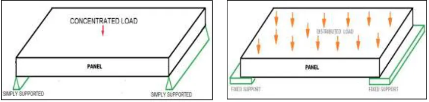
In this paper we have analyzed panels using rectangular steel plate as stiffener and two different edge conditions- Simply supported at two opposite edges (short edges), other two edges free
Fixed support at two opposite edges (short edges), other two edges free.
Typical application for simply supported with concentrated load and fixed support with distributed load is shown in the fig 2 and fig 3.
II. MATERIAL PROPERTIES TAKEN FOR ANSYS ANALYSIS
Material properties used for ANSYS is shown in table 1.
Table – 1
Material Properties used for ANSYS Analysis 1 Material Structural Steel 2 Grade IS 2062 3 Y.S. 250 x 106 N/m2 4 UTS 410 x 106 N/m2 5 Compressive 500 x 106 N/m2 6 Poisson’s Ratio 0.3 7 Young’s Mod 2 x 10¹¹ N/m2 8 Mod of Rigidity 2 x 10¹¹ N/m2
III. ANSYS ANALYSIS DATA
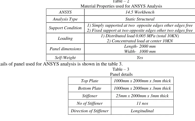
ANSYS analysis data used for analysis are mentioned in table 2. Table – 2
Material Properties used for ANSYS Analysis
ANSYS 14.5 Workbench
Analysis Type Static Structural
Support Condition 1) Simply supported at two opposite edges other edges free 2) Fixed support at two opposite edges other two edges free
Loading 1) Distributed load 0.005 MPa (total 10KN) 2) Concentrated load at center 10KN
Panel dimensions Length- 2000 mm Width- 1000 mm
Self-Weight Yes
Details of panel used for ANSYS analysis is shown in the table 3. Table – 3 Panel details
Top Plate 1000mm x 2000mm x 3mm thick
Bottom Plate 1000mm x 2000mm x 3mm thick
Stiffener 25mm x 2000mm x 3mm thick
No of Stiffener 11 nos
Direction of Stiffener Longitudinal
IV. TABULATED RESULT OF ANSYS ANALYSIS
ANSYS results for the model with various support conditions and loads are given below.
Case-I
Simply Supported at two edges (shorter) other edges (longer) free Distributed load 10 KN (0.005 MPa) on top plate.
ANSYS result for the above condition is mentioned in table 4 and ANSYS analysis pictures are given in fig 2, fig 3, fig 4 & fig 5. Table – 4
ANSYS Result for Panel- Simply Supported with Distributed Load Max Equivalent Stress 35.602 MPa
Fig. 2: Model with Mesh Fig. 3: Simply supported with distributed load: Load and support
Fig. 4: Simply supported with distributed load: Equivalent Stress Fig. 5: Simply supported with distributed load: Total deformation
Case-II
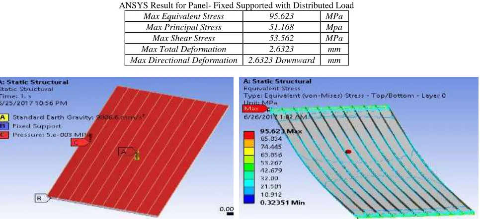
Fixed Support at two edges (shorter) other edges (longer) free & Distributed load 10 KN (0.005 MPa) on top plate.
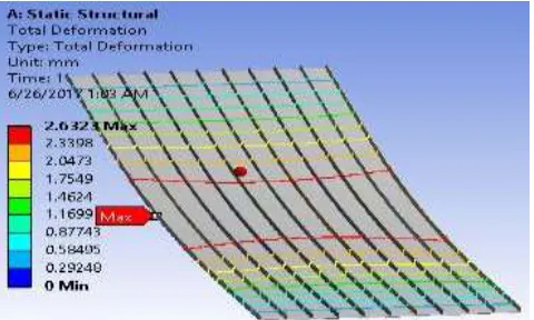
ANSYS result for the above condition is mentioned in table 5 and ANSYS analysis pictures are given in fig 6, fig 7 & fig 8. Table – 5
ANSYS Result for Panel- Fixed Supported with Distributed Load Max Equivalent Stress 95.623 MPa
Max Principal Stress 51.168 Mpa Max Shear Stress 53.562 MPa Max Total Deformation 2.6323 mm Max Directional Deformation 2.6323 Downward mm
Fig. 8: Fixed support with distributed load: Total deformation
Case-III
Simply Support at two edges (shorter) other edges (longer) free & concentrated load 10 KN on top plate.
ANSYS result for the above condition is mentioned in table 6 and ANSYS analysis pictures are given in fig 9, fig 10 & fig 11. Table – 6
ANSYS Result for Panel- Simply Supported with Concentrated Load Max Equivalent Stress 194.23 MPa
Max Principal Stress 163.22 Mpa Max Shear Stress 111.08 MPa Max Total Deformation 5.4033 mm Max Directional Deformation 5.4033 Downward mm
Fig. 9: Simply supported with concentrated load: load and support Fig. 10: Simply supported with concentrated load: Equivalent stress
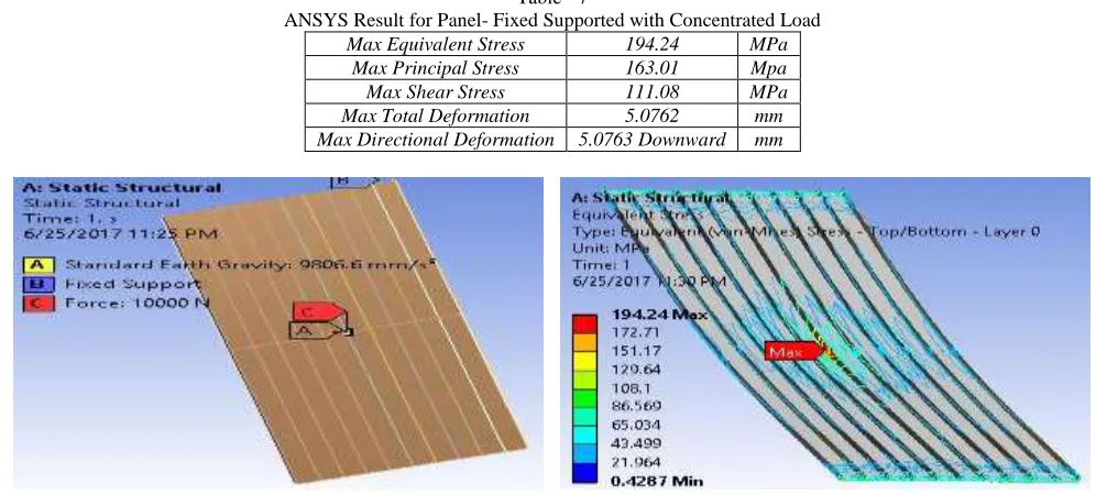
Table - 7
ANSYS Result for Panel- Fixed Supported with Concentrated Load Max Equivalent Stress 194.24 MPa
Max Principal Stress 163.01 Mpa Max Shear Stress 111.08 MPa Max Total Deformation 5.0762 mm Max Directional Deformation 5.0763 Downward mm
Fig. 12: Fixed support concentrated load: load and support Fig. 13: Fixed support concentrated load: Equivalent stress
Fig. 14: Fixed support concentrated load: Total Deformation
V. CONCLUSION
Following conclusions can be drawn from ANSYS analysis results discussed above. 1) Panel having two sides fixed results more stress as compared to simply supported one.
2) For concentrated load at center generates about double max equivalent stress as compared to distributed load. 3) For concentrated load at center generates about double total deformation as compared to distributed load. 4) Max deflection always occurs at center on plate which is in agreement with standard strength of material result.
5) For panel having concentrated load at center max stress always generated at the location of application of load i.e. on the center of plate.
6) For simply supported panel with distributed load center max stress generated at the location of support not on the center of plate.
During designing panel element for load bearing component above points are to be considered.
REFERENCES
[1] Patil,M.S., Date,D.D.andGhalke, A.B., "Design And Analysis Of Light Weight Steel Sandwich Panels Using ANSYS Workbench", Indian Streams Research
Journal, Dec 2005, pp.1-14
[2] V. Palanivelrajan, A.S. Selvakumar., “Design and analysis of corrugated sandwich Panel for structural applications” , Indian Journal Of Applied Research,
Volume:5 ,Issue:6, June 2015, ISSN - 2249-555X pp-674-677
[3] Bagadi, Gopi Krishna; B. Rambabu, “Design and Analysis of Stainless Steel and Mild Steel Sandwich Composite Structure”, IJMETMR Vol-2, April 2015,