CFD ANALYSIS OF THE SMALL HORIZONTAL
AXIS WIND TURBINE BLADE WITH AND WITHOUT
WINGLETS
*P.Premalatha, **S.Rajakumar, *PG student, ** Assistant Professor, Department of Mechanical Engineering,
Regional centre, Anna university Tirunelveli Region, Tirunelveli, India
ABSTRACT
In this paper computational studies are carried out to obtain the aerodynamic characteristics of winglets added with small horizontal axis wind turbine rotor blades. To develop a small horizontal axis wind turbine rotor blade with and without winglets. Usages of small wind turbines are limited due to their limitations in self starting, low wind speed conditions and efficiency. The winglets added with small wind turbines, is to reduce the self-starting requirement and to improve the power coefficient of wind turbine system. NACA airfoil profile is considered for analysis of wind turbine blade. NACA 63215 airfoil profile used in the root section modified NACA 63(2)215 airfoil used in the mid section and NACA 63415 airfoil used in the tip section of the rotor blade. In this paper focuses on winglet height, cant angle and curvature radius which effects on small horizontal axis wind turbine in order to improve the coefficient of power. Five rotor models are designed. Among five rotor models one of the model without winglet and four of the models with variation in height, cant angle and radius of curvature. Wind turbine blade having winglets for different angle foe aerodynamic performances. CREO software is used to design a small wind turbine blade with and without winglet. By using Ansys fluent 14.5 CFD software used for Analysing of wind turbine blade with and without winglets.
Keywords: Small Horizontal Axis Wind Turbine (HAWT), Winglet, Wind Turbine Rotor Blade
INTRODUCTION
CALCULATION OF BLADE DESIGN
The blade was designed by following tabulation. It was calculated from the blade design formulas. First wind turbine power formula is used to find the radius of the small wind turbine blade. Blade was divided into various section of element. After using the formula to calculate the chord, angle of rotation and relative flow angle .These values are useful to design a small wind turbine blade.
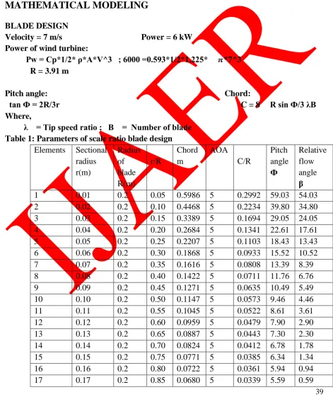
MATHEMATICAL MODELING
BLADE DESIGN
Velocity = 7 m/s Power = 6 kW Power of wind turbine:
Pw = Cp*1/2* ρ*A*V^3 ; 6000 =0.593*1/2*1.225* *7^3
R = 3.91 m
Pitch angle: Chord:
tan Ф = 2R/3r C = 8 R sin Ф/3 λB Where,
λ = Tip speed ratio ; B = Number of blade Table 1: Parameters of scale ratio blade design
18 0.18 0.2 0.90 0.0643 5 0.0321 5.29 0.29 19 0.19 0.2 0.95 0.0609 5 0.0304 5.01 0.01
20 0.2 0.2 1 0.0579 5 0.0289 4.76 -1.76
PROPOSED INITIAL DESIGN
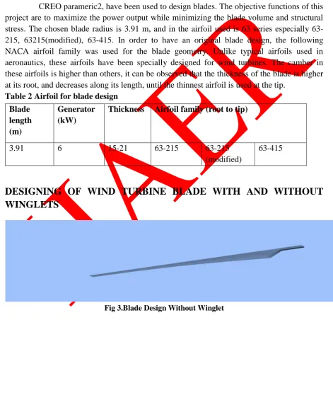
CREO parameric2, have been used to design blades. The objective functions of this
project are to maximize the power output while minimizing the blade volume and structural stress. The chosen blade radius is 3.91 m, and in the airfoil used is 63 series especially 63-215, 63215(modified), 63-415. In order to have an original blade design, the following NACA airfoil family was used for the blade geometry. Unlike typical airfoils used in aeronautics, these airfoils have been specially designed for wind turbines. The camber in these airfoils is higher than others, it can be observed that the thickness of the blade is higher at its root, and decreases along its length, until the thinnest airfoil is used at the tip.
Table 2 Airfoil for blade design
DESIGNING OF WIND TURBINE BLADE WITH AND WITHOUT
WINGLETS
Fig 3.Blade Design Without Winglet
Blade length (m)
Generator (kW)
Thickness Airfoil family (root to tip)
3.91 6 15-21 63-215 63-215
(modified)
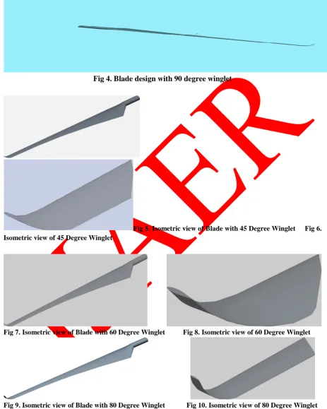
Fig 4. Blade design with 90 degree winglet
Fig 5.Isometric view of Blade with 45 Degree Winglet Fig 6. Isometric view of 45 Degree Winglet
Fig 7. Isometric view of Blade with 60 Degree Winglet Fig 8.Isometric view of 60 Degree Winglet
Fig 11.Isometric view of Blade with 90 Degree Winglet Fig12. Isometric view of 90 Degree Winglet
ANALYSIS OF WIND TURBINE BLADE
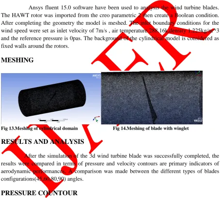
Ansys fluent 15.0 software have been used to analysis the wind turbine blades.
The HAWT rotor was imported from the creo parametric 2 then create a Boolean condition. After completing the geometry the model is meshed. The inlet boundary conditions for the wind speed were set as inlet velocity of 7m/s , air temperature 288.16k,density 1.225kg/m^3 and the reference pressure is 0pas. The background of the cylindrical model is considered as fixed walls around the rotors.
MESHING
Fig 13.Meshing of cylindrical domain Fig 14.Meshing of blade with winglet
RESULTS AND ANALYSIS
After the simulation of the 3d wind turbine blade was successfully completed, the results were compared in terms of pressure and velocity contours are primary indicators of aerodynamic performances. A comparison was made between the different types of blades configurations(45,60,80,90) angles.
PRESSURE COUNTOUR
Fig 15.Pressure contour (winglet 45deg) Fig 16.pressure contour (winglet 60deg)
Fig 17.Pressure contour (winglet 80deg) Fig 18.Pressure contour (winglet 90deg)
VELOCITY CONTOUR
The figure shows the velocity contour on rotor for 7m/s of inlet air velocity where the
Fig 19.Velocity contour (winglet 45deg) Fig 20.Velocity contour (winglet 60deg)
Fig 21.Velocity contour (winglet 80deg) Fig 22.Velocity contour (winglet 90deg)
RPM ON THE BLADE WITH WINGLETS
N
N=489.78rpm (winglet 45deg) N=489.35rpm (winglet 60deg) N=496.99rpm (winglet 80deg) N=471.21rpm (winglet 90deg)
FORCES ON THE BLADES AND THRUST ON TURBINE Torque becomes
T =
7.199 N
7.186 N
7.412 N
6.663 N
CONCLUSION
Small horizontal axis wind turbine blade designed with various angle of winglets by
using Creo parametric2 software. Winglets are used to increase the aerodynamic characteristics. Smaller curvature radius with sufficient height of winglet added to the wind turbine rotor captures more energy in low wind speed region as against plain wind turbine rotors without the provision of winglet. So I choose to design the wind turbine blade with winglet increasing winglet height and also decreasing curvature radius with different angles. The calculation shows when using blades with and without winglet at air velocity 7m/s it was observed that, the maximum pressure are (21.967,22.582,21.479,22.135)pa, velocity contour are (10.258,10.249,10.409,9.869) m/s, torque on the blade when winglet at various angles are (13.498,13.475,13.899,12.494)N-m and axial forces acts on the blade with various winglets are (7.199,7.186,7.412,6.663)N. According to the results obtained from the analysis program, the best winglet angle is 80 degree because the pressure around this winglet is less whereas velocity is high.
REFERENCES
1. Abdul kaddir, Harun Chowdhury, Bavin Loganathan and Firoz Alam “ An aerodynamic study of a domestic scale horizontantal axis wind turbine with varied tip configurations” 6th
BSME International Conference on Thermal Engineering (ICTE 2014)
2. M.Lydia, S.Suresh kumar, A.Immanuel Selva kumar, G.Edwin prem kumar “Acomprehensive review on wind turbine power curve modelling techniques” Department of Electrical & Electronics Engineering, Karunya University, Coimbatore 641114, Tamilnadu, India
3. R.N.Sharma, U.K.Madawala” The concept of a smart wind turbine system” Department of Mechanical Engineering, private Bag 92019, THE University of A UCKLAND 114, New Zealand
4. Jeppe johansen and Niels N.Sorensen “Aerodynamic investigation of winglets on wind turbine blades using CFD”, Riso-R-1543(en) Feb 2006.
6. Monier A.Elfarra,Nilay Sezar Uzol and I.Sinan Akmandor “Investigation on Blade Tip Tilting for Hawt Rotor Blades Using CFD” International journal of green energy(2015)12, 125-138
7. Johanson, J. and Sorensen, N.N. “Numerical Analysis of Winglets on Wind Turbine Blades using CFD”, EWEC 2007, May 07-10, 2007.
8. Drew Gertz,David A.Johnson and Niel Swytink Binnema “Comparative Measurements of the Effect of a Winglet on a Wind Turbine” Wind Energy 2014 9. Monier A.Elfarra,Nilay sezar-Uzol and Sinan Akmandor “NREL VI rotor blade:
numerical investigation and winglet design and optimization using CFD” Wind energy 2014; 17:605-626
10. Saravanan.P,Parammasivam K.M and Selvi Rajan.S “Experimental Investigation on Small Horizontal Axis Wind Turbine Rotor Using Winglets” Journal of applied science and engineering, Vol.16, No.2,pp. 159-164(2013)
11. N.Manikandan,B.Stalin “Design of NACA63215 Airfoil for a Wind Turbine” Volume 10, Issue 2(Nov-Dec.2013), PP 18-26
12. Drew Gertz and David A.Johnson “An evaluation testbed for wind turbine blade tip designs – baseline case”Int.J.Energy Res.2011; 35:1360-1370
13. J.Johanson,M.Gaunaa and N.Sorensen “Increased Aerodynamic Efficiency On Wind Turbine Rotors Using Winglets” AIAA 2008-6728
14. Prof, G.Sivaraj, Mr.M.Gokul raj “Optimum Aerodynamic Design in Wind Mill Blades Using Winglet Function” Volume 1.Issue 2 (May 2012),pp.18-24