15 Available online at www.ijiere.com
International Journal of Innovative and Emerging
Research in Engineering
e-ISSN: 2394 - 3343 p-ISSN: 2394 - 5494
Two Stage Grid Connected PV System
Sunil Salvi
1, Hardik P Desai
1Department of Electrical Engineering, SCET, Surat, Gujarat, India1
ABSTRACT:
In the two stage grid-connected photovoltaic systems which can procedure as domestic applications. This system contains of a two power converter phases (1) DC-DC boost converter and (2) DC-AC inverter. The switching scheme of inverter contains with a combination of sinusoidal pulse width modulation (SPWM) and square wave along with grid synchronization form. The performance of inverter is simulated under grid-connected situation using MATLAB. Furthermore, the intelligent PV module system is implemented using a simple maximum power point tracking (MPPT) method employing power balance is also engaged in order to rise the systems efficiency. Keywords: Photovoltaic , DC-DC Boost Converter, DC-AC Inverter , MPPT, SPWM and Grid
I. INTRODUCTION
The concern of alternative energy systems has been increasing continuously. Among them, the solar energy system is one of the important solutions because it produces electric power without inducing environmental pollution. Specifically, many studies regarding the reduction of the development cost for solar energy systems have progressed widely.
The solar array has a nonlinear voltage-current (V-I) characteristic, and an operation condition of the maximum solar-power delivered from the solar array exists which varies according to solar illumination and array temperature. Thus, to effectively use solar-power, the maximum power condition needs to be tracked by an MPPT control [1].
Most of the traditional photovoltaic (PV) supply systems are composed of multi-stage converter. The input-stage DC/DC converter is used to promote the input voltage and to draw the maximum power of solar energy source while the output-stage inverter is used to supply AC power to various AC loads. Such a system will cause much power dissipation due to multi-stage structure. In addition, when the illumination is insufficient during a cloudy day, rainy day or night, the PV supply system will suspend work. Thus, the overall utility of the PV supply system will greatly reduce.
For solving the above problems, a DC power system with PV grid-connection is explained in this. the output voltage of PV array is promoted only via single-stage DC/DC converter and supply directly DC power to the DC loads. Thus, the power dissipation which results from multi-stage converter will be improved. Besides, for promoting effectively the utility of PV supply system, the system except fed the surplus PV power to the grid via DC/AC inverter, the grid can also supply insufficient power to the AC loads during illumination insufficient [2] fig.1 shows the block diagram of Two stage Grid Connected PV system.
Depending on the AC side loads, the PV power generation has been classified into the grid-connected and the stand-alone systems . For the grid-connected PV generation system, it can be further grouped into the single stage system and the two-stage system. Generally, there are two control tasks in the PV power generation system:
(1) Is to regulate the output currents of the inverter to meet the grid code.
(2) Is to implement the maximum power point tracking (MPPT) of the PV modules .
In the single-stage PV system, these two control tasks are realized in one power conversion stage. Thus, the system configuration can be simplified [3].
16 characteristics of this diode therefore sets the open circuit voltage characteristics of the cell [4][9].
1 1/
1
1
x V bV b x bI
I
e
e
………(1)( 1) 1
( ) max max 1 1 ln 1 op x n b n op sc V V b
P P e
V I ………(2) P=VI……….(3)
where, Ix is the short circuit current under Standard Test Conditions (STC), and Vx is the open circuit voltage under STC, and b is the characteristic constant of the panel and can be approximated by equation (2) with Vop is the voltage At which the maximum power is extracted from the panel and Pmax is the maximum power point of the panel, all under STC. The proposed inverter design is used an intelligent PV module concept that includes a DC-DC converter with MPPT controller.
Figure 2: The circuit diagram of the PV model [4]. Table 1: The Key specification of the Solarex TBP1260 PV Panel.
Peak Power(Pmax) 60.0W
Voltage (Vmp) 18.2 V
Current (Imp) 3.3 A
Open Circuit Voltage (Voc) 21.8 V Short Circuit Current (Isc) 3.56 A Minimum Bypass Diode Current 9 A
Maximum Series Fuse 8 A
Solar irradiance G 1000 W 2
m
Cell Temperature 250
C
III.DC-DCBOOST CONVERTER WITH MPPT
A: DC-DC Boost Converter
17 Figure 3: MATLAB Model of DC-DC Boost Converter with MPPT
………..(4)
B: MPPT
A typical solar panel converts only 30 to 40 percent of the incident solar irradiation into electrical energy. Maximum power point tracking technique is used to improve the efficiency of the solar panel.
According to Maximum Power Transfer theorem, the power output of a circuit is maximum when the Thevenin impedance of the circuit (source impedance) matches with the load impedance.
In the source side we are using a boost convertor connected to a solar panel in order to enhance the output voltage so that it can be used for different applications like motor load. By changing the duty cycle of the boost converter appropriately we can match the source impedance with that of the load impedance[5]
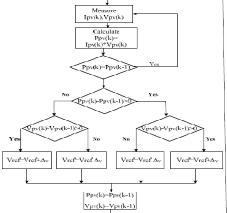
Perturb & Observe (P&O) is the simplest method. In this we use only one sensor, that is the voltage sensor, to sense the PV array voltage and so the cost of implementation is less and hence easy to implement. The time complexity of this algorithm is very less but on reaching very close to the MPP it doesn’t stop at the MPP and keeps on perturbing on both the directions. When this happens the algorithm has reached very close to the MPP and we can set an appropriate error limit or can use a wait function which ends up increasing the time complexity of the algorithm. However the method does not take account of the rapid change of irradiation level (due to which MPPT changes) and considers it as a change in MPP due to perturbation and ends up calculating the wrong MPP. [6] Fig.4 shows the Algorithm of Perturb and Observation (P&O) Method
Figure 4:Algorithm of P&O method[6]
1
1
outin
V
18 Figure 5: Model of DC-AC inverter [7]
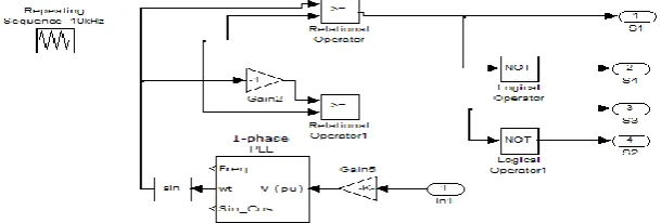
For synchronization between grid and inverter Phase locked loop (PLL) technique is used. The basic structure of PLL is as shown in Fig.6
Figure 6: Closed loop Synchronization structure[8]
V. SIMULATION RESULTS
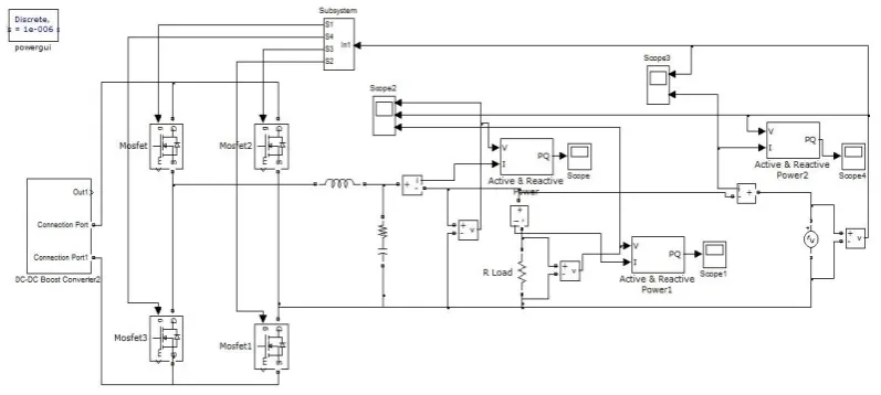
Fig.7 Shows the Simulink model of single phase grid connected PV system where LC Filter is used where L=4 mH and C=10𝜇𝐹
Figure 7: Simulink model of single phase Grid Connected PV system
19 Figure 8: Closed loop for single phase Grid Connected PV system
Fig. 9 &10 Shows the IV and PV curves For the Parameters of Table:1 For different irradiance variation
Figure 9: IV curves for various irradiation levels Figure 10: PV curves for various irradiation levels
Fig.11 Shows the Input voltage(a) which is 90V (5 Panel in series) and Input Current(b) which is 3.45 A
Figure 11: Input Voltage(a) and Current(b) DC-DC Boost Converter
20 Figure 12: Output Voltage(a) and Current(b) DC-DC Boost Converter with P&O method
Fig.13 Shows Input and Output Power of DC-DC Boost Converter with P&O method where yellow line suggest input power which is 300W and Magenta Line suggest output Power which is 287W
Figure 13: Input and Output Power of DC-DC Boost Converter with P&O Method
Fig.14 shows the Voltage of Inverter(a),Grid(b), and load (c) where all voltage are in synchronization
Figure 14: Results of Voltage of Inverter, Grid and Load
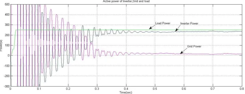
21 Figure 15:Results of Active power of Inverter, Grid and Load
VI.CONCLUSIONS
The work presented in is Characteristics of IV and PV for different irradiation, DC-DC Boost Converter with MPPT. The technique which is used in MPPT is Perturb & Observation Method, The Results of DC-DC Boost Converter
Input and Output Power With P&O methods of MPPT at T=250 C and Suns=1, Synchronization of inverter and Grid with MATLAB simulation also shown the results of Inverter, Grid and Load Voltages and Power.
REFERENCES
[1] H. S. Bae, J. H. Park,B. H. Cho and G. J. Yu,“New Control Strategy for 2-stage Utility- Connected Photovoltaic Power Conditioning System with a low cost digital processor” IEEE Trans. Power Electron.,pp.2925-2929,2005. [2] Yu-En Wu and Chih-Lung Shen,“Implementation of a DC Power System with PV Grid-Connection and Active
Power Filtering”, IEEE Trans. Power Electron.,pp-116-121,2010.
[3] Zheng Wang, Shouting Fan, Yang Zheng and Ming Cheng, “Control of a Six-Switch Inverter Based Single-phase Grid-Connected PV Generation System With Inverse Park Transform PLL”,IEEE Trans. Power Electron., pp.258-263,2012.
[4] Walker, Geoffrey R. “Evaluating MPPT converter topologies using a MATLAB PV model” , Innovation for Secure Power, Queensland University of Technology, Brisbane, Australia, pp. 138-143,2000.
[5] Almas Hossain Mollah, Prof. G K Panda and Prof. P K Saha, “Single Phase Grid-Connected Inverter for Photovoltaic System with Maximum Power Point Tracking” IJAREEIE, Vol. 4, Issue 2, February 2015.
[6] Houda ABIDI, Afef Bennani Benabdelghani, Daniel Montesinosmiracle “MPPT Algorithm and Photovoltaic Array Emulator using DC/DC Converters”, IEEE,pp.567-572,2012.
[7] Kleber C. A. De Souza, Walbermark M. dos Santos and Denizar C. Martins, “ A Single-Phase Active Power Filter Based in a Two Stages Grid-Connected PV System” IEEE,pp.114-119,2009.
[8] Mitra Mirhosseini, Josep Pou and Vassilios G. Agelidis, “Single- and Two-Stage Inverter-Based Grid-Connected Photovoltaic Power Plants With Ride-Through Capability Under Grid Faults”, IEEE Trans. Power Electron., Vol.6, No. 3, pp.1150-1159,July 2015.
[9] Chetan Singh Solanki, “Solar Photovoltaics: Fundamentals,Technologies and Applications”, Second Edition,July-2011.
![Figure 1: Block diagram of Two Stage Grid Connected PV System [1]](https://thumb-us.123doks.com/thumbv2/123dok_us/8874935.1816289/1.595.159.470.638.733/figure-block-diagram-stage-grid-connected-pv.webp)
![Figure 2: The circuit diagram of the PV model [4]. Table 1: The Key specification of the Solarex TBP1260 PV Panel](https://thumb-us.123doks.com/thumbv2/123dok_us/8874935.1816289/2.595.139.421.494.615/figure-circuit-diagram-model-table-specification-solarex-panel.webp)