Virtual User Interface for the Remote Control of a
Nano-Robotic Cell Using a Haptic-Device
Gregor Škorc1,*_ Simon Zapušek2 - Jure Čas3 - Riko Šafarič2 1RESISTEC UPR d.o.o. & Co. k.d., Slovenia
2University of Maribor, Faculty for Electrical Engineering and Computer Science, Slovenia 3EM. TRONIC d.o.o., Slovenia
This paper describes the development of a virtual user interface for the remote control of a nano-robotic production cell. The user interface combines two different software applications, built on two different software platforms. The first-host application is based on a LabView 8.5 software package and runs on a real-time target. It is used as a communication interface between the nano-robotic cell and a remote user interface. The remote application was created within a Microsoft Visual C 6.0 software package using C++ programming language. It is used for the virtual remote control of a nano-robotic cell. Depending on production demands, the remote user can choose between two different control techniques. The first one is a classical input algorithm where the user sets any move trajectory of the nano-robotic cell directly through a remote user interface. Each axis separately or all axes together can be moved in this way. Another control option supports acquiring movement trajectory using a haptic-device. In this regime the user receives real-time force feedback information which makes remote control even more realistic. Both control regimes are supported by an animated, virtual, VRML model of the target application. This VRML model is used for off-line simulation or real-time monitoring of the target application movement. UDP protocol is used as a basic communication protocol between the host and remote applications.
© 2010 Journal of Mechanical Engineering. All rights reserved.
Keywords: virtual remote control, nano-positioning, VRML, LabVIEW Real Time, MEMS assembly
0 INTRODUCTION
Nano-technologies are actual and promising research fields nowadays. A lot of a work within nano-scale has already been published. Our work finds its place within a special part of nano-technologies namely automated nano-positioning and nano-assembly. The sizes of manipulated parts are demanding especially clean working environment, therefore nano-applications are often built within vacuum chambers. These chambers usually include a semi-electronic microscope or special camera systems, for monitoring the processes. Authors have presented a solution for automated nano-positioning, based on SEM visual feedback in [1]. Another solution, where visual feedback was achieved using CCD camera and microscope is presented in [2]. A general review of scanning probe-based 2D nano-manipulation and gripper-based 3D nano-handling is given in [3]. Special user interfaces in combination with a
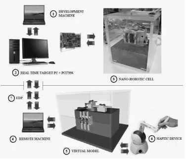
solution for this problem, based on two different software applications (Fig. 1). The first runs on a host computer and can be used for local control of the target application. Because of the local character of the application, it supports a live camera picture. The second application is a remote application which remotely communicates with the host application, and gives full support to the haptic-device. In remote application we have replaced live camera picture with a virtual model, which is animated with real time positional information extracted from control data packets. Broadcasting of live camera pictures was disabled (the lack of a live camera picture has been replaced by a corresponding virtual model) and the part of communication capacities was released. Because the model animation algorithm runs on the remote computer, and live camera picture is not transmitted anymore, is amount of transmitted data reduced to minimum. The virtual model is used for collision detection and
calculation of feedback forces for the haptic-device, in continuation. The model gives us, in this case, even more opportunities for upgrading the application with newer functions than a camera picture gives. The developed application scales real operations within nano-scale, into virtual animation within macro scale. A communication link between the nano and macro worlds is established. In comparison to systems [1] to [3], where control of positioning device has a local character, our system gives an opportunity to overtake control remotely. Positioning is possible with accuracy of 61 nm and speeds of up to 35 mm/s. System is basically being developed for a purpose of MEMS assembly. Presented remote interface makes it useful even in a process of e-learning, within lectures of remote control engineering, at the University of Maribor, Faculty for Electrical Engineering and Computer Science, Slovenia.
Section 1 gives an overview of the used system components and presents there functionalities. A presentation of the host applications development, with description of the UDP (User Datagram Protocol) sender and receiver algorithm built within LabView software package is given in 2. Section 3 describes the development of the remote application, virtual model, and haptic device application programming interface (HDAPI) program built within C++ programming language. Section 4 shows the practical application and, finally, section 5 provides the conclusions of the work.
1 SYSTEM COMPONENTS
The whole system can be divided on host and remote level as presented on Fig. 1. Host application is basically being developed for a purpose of MEMS assembly. Remote application extends functionality of the host application on that way that it simplifies programming of host application and allows remote programming (or monitoring) of it. Both application levels form closed application which can be used for different purposes. If such application is used as a production cell within some company, it eliminates need for “full-time” presence of expert engineer at the production line. Expert engineer can access host application remotely and remotely reprogram production process (or define production errors with monitor function). Small size of data packets, transmitted between host and remote application, make remote control possible even with mobile devices such as smart phone or PDA (under the condition that mobile device has access to public internet and preinstalled remote control software). Another possible use of presented system is in process of training of engineers or in the process of e-learning of students. Because remote interface includes functions for collision detection, real application cannot be harmed in the case of wrong preprogramming. Simulation functions built within remote interface make success of such training even better.
As already mentioned, the host level presents a real-time target application with nano-robotic cell (presented over a line in Fig. 1). It consists of a development computer marked as number 1, a real-time controller marked as number 2 and a target application marked as
number 3. Development computer is based on a Windows XP platform and supported by a LabView 8.5 software package. Primarily it is used for developing control algorithms and user interfaces, but can also be used for the execution of control algorithms. In this case we must take into account the limited frequencies of the program routines, which cannot achieve higher frequencies than 1 kHz. A better solution is the addition of a separate computer to the control system, which is then used only for the execution of control algorithms. Such a computer is presented in Fig. 1 and marked as number 2. A Real-time Desktop Target PC was built for this purpose. This dual processor PC is based on a LabView Real Time OS. The execution times of the control algorithms are drastically reduced, and execution frequencies of up to 1 MHz can be achieved. Our real-time target PC (Fig. 1, number 2) is supported by a 7356 PCI motion controller card from National Instruments [7]. This card is capable to serve 6 independent axes (in our case we use 5 axes configuration), based on a positional feedback information’s from encoders and on-board PID controller. We have configured this card so that it acts as stepper driver, therefore, all axis outputs act as a STEP/DIRECTON outputs. An alternative configuration of this card, as servo driver, is also possible. On-board outputs and inputs are defined within TTL logical levels. Common robotic control functions (e.g. circular interpolation, linear interpolation, PTP move, SIN2 profiling and trajectory tracking) are supported in combination with LabView libraries.
guarantees a resolution of 61 nm, with precision of 0.15% [9].
Fig. 2. Motors movement directions
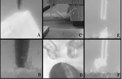
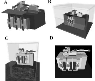
The built nano-robotic cell allows implementation of different micro and nano robotic-tools (Fig. 3). Figs. 3A and B present an influence of parasitic forces which can be used to
handle micro – parts (with a use of special probe). The problem in this case is to release the manipulated object. Temporally, we are using a special PZT gripper (Figs. 3C and D) which is used for gripping those objects of micro-scale size. It is placed at the top of the Y axis. This gripper was developed by the Fraunhofer-Institute of Reliability and Microintegration, Germany. It was fabricated by means of a UV-lithographic process and chemical wet etching technology from microstructurable photosensitive glass [10]. Using little changes in the basic form of the gripper, we achieved a gripper movement of approximately 10 µm (neutral opening of the gripper tip is 200 µm). Gripper is actuated with a piezo electric actuator and served by a PZT power module (DC voltages from -100 to +100 V are used). Figs. 3E and F show manipulation with vacuum gripper similar to [11]. In this case the size of manipulated object is limited to the diameter of the used vacuum hose. All manipulated objects presented in the Fig. 3 have varied in size from 80 to 200 µm.
The lower level part of the application, presented under a line in Fig. 1 is a remote application. Remote application can be used either for direct control of tasks on nano-robotic cell, or either for teaching of new tasks. It consists of a remote computer marked as number 4, remote application with included virtual model marked as number 5, and a haptic-device marked as number 6. A remote computer is the common notebook, based on a Windows XP platform, supported by a Microsoft Visual C software package, C++ programming language, and an OpenHaptics software tool from Sensable. It is used for developing and executing the remote application. The user datagram protocol (UDP), marked as number 7, is used as a basic communication protocol on the transport layer within internet protocol (IP) on the network layer. The virtual VRML model marked as number 5 is also included in remote application. Because the remote user does not see the target application, it does not have a real feeling as to what exactly is happening to the target. There exists a risk of development hazardous. The model is used for animating the situation on the target application, which gives a realistic representative to the user who is remotely controlling the target. Model can be animated with online data acquired from the target application (encoder data extracted from transmitted data packet), offline data acquired from the simulation results (simulations are a function of the remote interface), or online data acquired from the haptic-device (built-in function of the remote interface). In order to provide a remote user with even more realistic representation about the situation on the target, the system uses a Phantom Omni haptic-device (Fig. 1, marked as number 6). It is the most basic for haptic-devices produced by Sensable Technologies Company. The chassis of the device is very compact and has two free programmable built-in buttons. The user takes over control of the device by moving the arm of the haptic-device over 6 degrees of freedom (X, Y, Z, roll, pitch and yaw). Three motors are built onto the X, Y and Z axes to give the user force-feedback information as a representation of friction or space limits. The positions of each axis are measured using encoders or potentiometers. It communicates with an IEEE-1394 interface. Both application levels can be used independent from each other or in combination with both of them.
2 DEVELOPMENT OF THE HOST APPLICATION
As already mentioned, the host application uses a LabView 8.5 development platform, which simplifies programming of the target application. The control algorithm and user interface were developed within this package. The control algorithm, which is based on adaptive bang-bang control, has already been presented in one of our previous papers. This section will, therefore, concentrate just on those communication and user interface extensions added to the adaptive bang-bang control method.
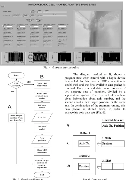
Fig. 4. A target user interface
Fig. 5. Receiver diagram
The diagram marked as B, shows a program state when control with a haptic-device is enabled. In this case a UDP connection is established and the first available data packet is received. Each received data packet consists of two separate sets of numbers, divided by a sepparation symbol. The first set of numbers gives information about axis number, and the second about a new target position for the same axis. In continuation of the program routine, this data packet is shifted twice, in order to extrapolate both data sets (Fig. 6).
The extrapolated axis number is used for controlling the case sentence, which orders a new target position for the proper axis variable. At the same time the axis number is forwarded to the sender module, where it is used as information about which axis current position shall be send to the remote application.
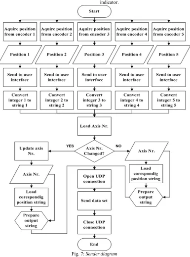
The diagram of the UDP sender module is presented in Fig. 7. It is built on the basis of recommendations from National instruments (LabView tutorial example). It has one mode of operation. The current position is acquired from the encoder as a number, saved in a local buffer, and sent to the user interface via an LabView indicator.
The position number is converted into a string, because the UDP sender uses a string format for sent data packets. We have added case sentence to the basic algorithm which combines axis number and corresponding axis current position into the extended data string (oposite procedure as presented on Fig. 6). The extended data string corresponds to the form of received data packets on the following way. The same string is finally sent to the remote application using a UDP sender algorithm (UDP port is opened, data packet is sent, UDP port is closed). Remote application receives positional information for one axis only at the same time.It is possible to configure the sender module so, that it sends information about all axes at the same time. We have constructed a test where the sent data package was formed so that positional information about the first axis was followed by positional information about four other axes, again separated by a separation symbol. In this case we had a problem of variation in position data package’s length, which is caused by changing of the single axis position data word’s length. Symbol which separates positional information for single axes was changing its position within the data package. Because our algorithm was always expecting the separation symbol at the same place within the data string, it has not referenced correct axis always. A more sophisticated method as shifting of the complete data package must be used for extracting single axis data, in this case. For this reason, we made a decision to transmit data packets for each axis, separately.
3 DEVELOPMENT OF THE REMOTE APPLICATION
Our first goal when developing the remote application was to build a virtual model which would fully represent the real application. The main reason for building the virtual model was the wish to make remote connection between host and remote application more stable and faster. In Section 2 we have shown that the host application has the possibility to broadcast a live camera picture. This function works fine as long as we have a fast internet connection between host and remote application. In the case of a slow conenction (e.g. mobile internet connection from local mobile operator), broadcasted camera data
fulfills all available communication capacities, which provides a serious threat to transmission of control-data packets. Because we were using UMTS connection from our local mobile operator (using USB – UMTS modem ZTE MF636), we will focus only on mobile internet connections in continuation. Commonly three different mobile internet connections are used. The first one is called Global System for Mobile communications (GSM), which offers communication speeds of up to 14.4 kbit/s. The second one is called General Packet Radio Service (GPRS) which offers communication speeds of up to 140.8 kbit/s. The third one is called Universal Mobile Telecommunications System (UMTS) and is temporarily the most actual mobile connection. Theoretically UMTS allows connections with speeds of up to 14 Mbit/s, but in practice are these speeds much lower (300 kbit/s to 3.6 Mbit/s). In our experiments we have even noticed connections with speeds lower than 50 kbit/s. A huge amount of transmitted picture data can cause delay in transition of control data packets.
One of the easiest solutions to this problem is disabling the camera broadcasting, which certainly releases connection capacitates, but at the same time causes a lack of visual feedback information to the remote user. A few other already known solutions to this problem are reducing picture resolution (reduction in pixels number), reduction of picture color depth (e.g. from 24 to 8 bit), reduction of the number of acquired frames (e.g. from 50 to 30 Hz) or use of a compression codec’s. We have defined minimum acceptable camera acquisition resolution as 640 x 480 pixels, minimum color depth as mono 8 bit mode and minimum refresh rate as 30 Hz. Size of the data packet was 1280 bytes in this case. For successful broadcasting of camera picture, stable connection with minimum speed of 307.2 kbit/s is required. In comparison with control data packet which has in our case a size of 8 bytes, requires camera data packet much more connection capacities.
application (control data packet). Internet connection is only used for transmission of positional control data packets (broadcasting of live camera picture was disabled, visualisation of production proces was done with animated model), and a fast internet connection is no longer needed. The implemented virtual model opens up a wide pallet of possible new functions that can be implemented in remote application. Some of them are collision detection, positional limitation, visualization, implementation of haptic-device etc. All these functions are executed locally on the remote computer, therefore, they do not require a good internet connection. We made a decision that we would use VRML language to develop the virtual model. Fig. 8 shows four different development stages. The model (Fig 8A) was developed using a ProEngineer software package. The ProEngineer is one of the contemporary 3D modeling programs used for the development of new products. Because all of the mechanics for the nano-robotic cell was developed within this package, was the easiest way to create a VRML model, to use a built-in
“export to VRML” function. Tests on the so-created virtual model have shown that a lot of processor power is needed to animate the movement. A detailed look at the exported source code showed that the built-in function exports a model in the form of a separate object points. VRML language supports options to create a virtual model based on primitive shapes such as squares, cylinders and cones. The development of the model on the basis of primitive shapes requires less code. Consequently, less processor power is needed to animate such a model. The virtual model programmed with primitive shapes is shown in Fig. 8B. Because the number of objects and with them connected mathematical functions was reduced, animations have run much faster on this model. From the beginning of the model development phase, was our goal to build as much as possible representative model of the host application. We decided to upgrade this model so, that basic objects of nano-robotic cell have been described with greater number of primitive objects and surface colors have been added to them. The result is presented in Fig. 8C.
Comparison with the real nano-robotic cell, as presented in Fig. 1 (number 3), shows that a very good representative is achieved. Unfortunately means increasing the number of primitive objects, a bigger need for processor power. To make remote control software useful even within mobile devices (e.g. PDA-s, smart phones) which have limited processor and memory capacities, we had to find a compromise between the realistic level of the model and processor usage. The model marked as letter C is an optimized model which is built as a remote application. It was tested on Windows based notebook presented in section 2 and HTC P3600 smart phone (haptic device was not used in this case).
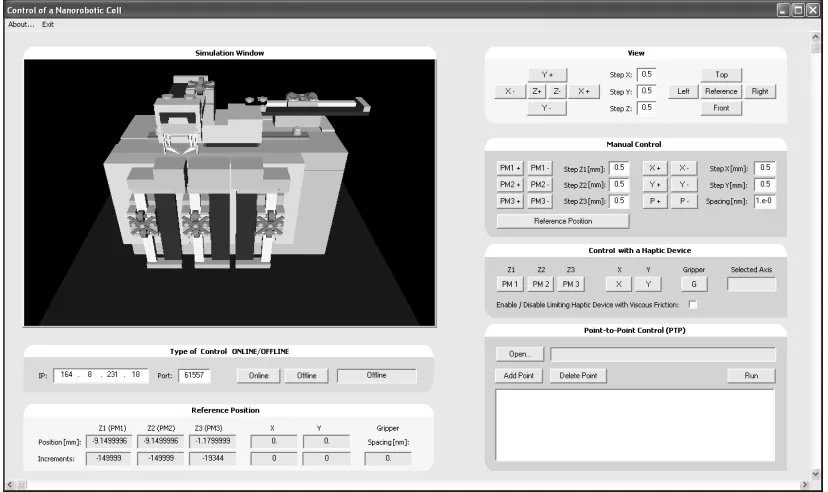
The next step in the development phase was development of the remote user interface. It was developed under the Miscrosoft Visual C 6.0 software package, C++ programming language, and support of a MSDN library. The functionality of the haptic-device was established with a Phanteon v4.2.118 driver package and OpenHaptics v1.02.50 software tool. The VRML model was implanted and animated with the use of a VRaniML library. The whole process was done on a Windows XP based computer. Fig. 9 presents a screenshot of a user interface. The implemented VRML model can be seen in the
upper left hand corner. The rest of the interface is divided into 6 sections. These are a view section, a manual control section, a section for control using the haptic-device, a section for control within a PTP regime, a section for selection between on-line/off-line control, and a referenced positional section. The view section is used for selection of the most appropriate view aspect on the VRML model. Integrated virtual buttons allow us to translate or rotate the view aspect within the user’s given steps. ZOOM function is also available within this section. The section for manual control is used for moving separate axes. Each axis has two virtual buttons. The first one is used for moving the axis one step forward and the other one for moving it one step backwards. The length of a motor step can be set individually. If the button is pressed continuously axis moves continuously in a give direction with a give step length. The section for control using the haptic-device is used for enabling of the HID regime and selection of the axis, which will be controlled by the haptic-device. Axis selection function is also available directly on the haptic-device with the use of one of the buttons integrated on the haptic-device. For safety reasons, HID regime still has to be enabled and confirmed within remote software. The number of the selected axis is shown within this section.
Moves are executed step by step as given in trajectory file. Any changes in position, within the described control sections are animated on the virtual model. The on-line/off-line section gives us a chance to simulate moves before they are transmitted to the real nano-robot cell. This option is given under the off-line regime, where any changes within any control section are executed as simulation on the virtual model. As soon as we enable an on-line regime, given changes are executed on the real application. This function is very helpful for testing some new trajectories. The last section is the reference position section, where we can set axes reference positions in certain specific cases, where default given references are unacceptable.
Because control user interface temporarly does not have ability to set user permisions (e.g. administrator or limited user), another user interface was built on the same basis, but only with the function of position monitoring of the target application. This interface uses C++ build receiver to animate the implemented VRML model.
All other fuctions available within the control user interface are disabled. This user interface is used only for a presentation purposes.
A complete source code for both user interfaces is very voluminous therefore, we focused only on that part which includes code for the haptic-device. Fig. 10 shows an execution diagram of our program. The first program steps are initialization of the haptic-device, enabling the force generator, a schedule callback and the start of a scheduler. This is followed by initialization of the frame within which runs a so- called servo-loop. In order to ensure stable work of the control program loop, must this loop run with frequencies higher than 1 kHz. The first step within the servo-loop is acquiring position, which is followed by enabling integrated buttons. We check the state of the integrated positional button in continuation. When the positional button is pressed, a relative change of position is calculated. The servo-loop is closed by enabling a friction function and applying feedback force in case a collision has been detected. Finally we change the position of the nano-robot.
4 PRACTICAL USE OF A BUILT SYSTEM
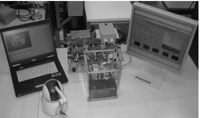
As we have already mentioned at the beginning of the paper we focused on the development of a nano-production cell. Until now we have prepared our application at a level which is capable of positioning of micro parts, with nano-meter accuracy. The final application is seen in the MEMS assembly process. For this purpose we still have to develop a suitable tools, which will allow us production of parts smaller than a few hundred micrometers. We are now developing a special gripper and special nozzle which will be used by first experiments of production. Paralely to the phase of developing the tools is our application used as an experimental object for the testing of new control techniques. Fig. 11 presents the temporary situation of our application.
Fig. 11. Temporary situation of the application
Presented application was verified according to two different tests, performed with reference signals within nano and macro scale. The first test was a step response test and the second was a trajectory tracking test. They have been performed with bang, adaptive bang-bang, fuzzy, adaptive fuzzy, polynomial and adaptive polynomial control techniques. Verification was done on a base of the size of a position overshot and an average positioning error. The best result was achieved using polynomial control technique where the size of the overshot was within 61 nm, and the size of average positioning error within 3 nm. Common to all tested techniques was, that they had produced always the same result either the system was controlled locally, either control was done remotely (using LAN or UMTS mobile network). Because of the small size of the transmitted
control data packet (8 bytes) this result was expected.
5 CONCLUSION
noticed problems connected with this weakness, but we must mention, that we have only one such system, communicating on a given communication port, reserved especially for it. We suppose that this weakness would cause troubles in case of multiple systems communicating over the same port. Solution for this problem is implementation of a more secured TCP protocol on transport layer. One of the future tasks in our work will be to examine possibility of integration of this protocol. Parallel with that we are focused on development of different tools for MEMS production.
6 ACKNOWLEDGEMENT
Operation part is financed by the European Union, European Social Fund.
7 REFERENCES
[1] Stolle, C., Fatikow, S. (2007). Control system of an automated nanohandling robot cell. 22nd International Symposium on
Intelligent Control, 1-3 Oct., Suntec City, p. 664-669.
[2] Fahlbusch, S., Fatikow, S. (2001). Implementation of self-sensing SPM cantilevers for nano-force measurement in microrobotics. Ultramicroscopy, vol. 86, no. 1, p. 181-190.
[3] Zuobin, W., Fatikow, S., Shizhong, S., Ming, Y. (2007). Robotic nanoassembly.
International Conference on Mechatronics
and Automation, 5-8 Aug., Harbin,
Heilongjiang, p. 422-427.
[4] Fahlbusch, S., Shirinov, A., Fatikow, S. (2002). AFM-based micro force sensor and
haptic interface for a nanohandling robot.
IEEE/RSJ International Conference on Intelligent Robots and System, Lausanne, Switzerland,vol. 2, p. 1772-1777.
[5] Lim, T., Ritchie, J.M., Corney, J.R., Dewar, R.G., Schmidt, K., Bergsteiner, K. (2007). Assessment of a haptic virtual assembly system that uses physics-based interactions.
International Symposium on Assembly and
Manufacturing, July 22-25, Ann Arbor,
p.147-153
[6] Iglesias, R., Casado, S., Gutierrez, T., Garcia-Alonso, A., Yap, K.M., Yu, W., Marshall, A. (2006). A peer-to-peer architecture for collaborative haptic assembly. International Symposium on Distributed Simulation and Real-Time Applications, 2-4 Oct., Torremolinos, p. 25-34.
[7] National Instruments, Motion controller 7356 datasheet, Retrieved on 05.01.2009 from http://www.ni.com/pdf/ products/ us/735x.pdf.
[8] Piezomotor Upsala AB (2003). PiezoLEGS data and user instructions, 3rd edition, p. 3-
15.
[9] Retrieved on 05.01.2009 from Nanos instruments web page: http://www.nanos-instruments.de/
[10] Keoschkerjan, R., Wurmus, H. (2002). A novel microgripper with parallel movement of gripping arms, Actuator, 8th International
Conference on New Actuators, June 10-12, Bremen, p. 321-324.