The physics of power systems operation
C. Ohler
ABB Switzerland, Corporate Research - CH-5405 Baden-D¨attwil, Switzerland
Summary.— The article explains the operation of power systems from the point of view of physics. Physicists imagine things, rather than in terms of impedances and circuits, in terms of fields and energy conversions. The account is concrete and simple. The use of alternating current entails the issue of reactive power. Reac-tive power consists of energy that oscillates between electrical and magnetic fields, it flows on top of the active power which carries the useful energy. The control of active and reactive power is essential for the power system’s reliable operation. The frequency of a power system is the same everywhere. The stability of the fre-quency indicates that generation and demand of active power are equal, a decline in frequency indicates a lack of generation relative to the demand. Adapting the electrical power injected into the system is the way of frequency control. Because of the parasitic inductances and capacitances of overhead lines, cables, and trans-formers, the voltage at different locations of the power system depends on the load. The voltage is regulated by the combined action of generator excitation, transformer tap changers and series compensation in order to provide consumers with a stable voltage supply. The integration of solar cells and wind turbines into the power sys-tem poses some challenges. But the power syssys-tem is able to accommodate large amounts of fluctuating renewable power generation if the right complementary mea-sures are taken.
/ / 98
7KLVLVDQ2SHQ$FFHVVDUWLFOHGLVWULEXWHGXQGHUWKHWHUPVRIWKH&UHDWLYH&RPPRQV$WWULEXWLRQ/LFHQVHZKLFKSHUPLWV C
1. – Introduction
A system is more than the sum of its parts. The power system is a good example of this statement. It has properties — frequency and voltage stability, flexibility of the power flow, continuous availability — that emerge from, but go beyond, the properties of the power system components.
In earlier articles [1, 2] the focus was on the physics of the components of the power system, what shape they take, what materials they are made of, and for what physical reasons. In this article we focus on theinteraction of the components and their control. How can a system composed of so many components provide a stable frequency and a stable voltage even though the power flow within the lines adapts all the time to the demand of the loads, that are switched on and off without any consideration of the power system’s condition? This is the question we try to answer. What is common with the earlier articles is that again a physicist’s perspective is adapted. Explanations use energy considerations rather than equivalent circuit impedances, and we treat the topic in an easily accessible way.
The next section gives a condensed description of the four main types of components that make up any power system. We move on to the definition of active and reactive power, that is essential for understanding the power system operation. In the core part of the article we explain frequency and voltage control. At the end, there is an outlook on the impact of renewables integration on the power system operation.
There are good textbooks that treat the subject in the electrical engineering language. For a recent concise introduction, see ref. [3]. A classic and elaborate treatment is provided in ref. [4].
2. – Power system components
Power systems are made from four main types of components. It is instructive to recall how the geometrical shape and the physical properties of the components follow from the functions required for the power system as a whole [1].
High-voltage overhead lines enable long distance power transmission with low losses. The voltage needs to be high to keep the losses at acceptable levels, but the high voltage requires large insulation distances — towers — and it imposes the need for alternating current because alternating current can be transformed using the principle of magnetic induction while direct current cannot.
It is advantageous to provide alternating current with three balanced, symmetric phases, each carrying a sinusoidal current of the same magnitude and frequency, but their zero crossing being displaced by one third of the period against each other. Such arrangement provides a steady, time independent, power flux from alternating current, and the return conductors of each phase can be omitted, thus saving half of the conductors material cost.
3. – Active and reactive power
For good reasons most introductory textbooks on power systems start with the dis-tinction between active and reactive power flow. This is a conceptual disdis-tinction that divides a single physical entity, the average power flow along a power line, into two notional components.
Power plants convert other forms of energy into electrical energy and feed it into the power system with the generator, this is the active component of the power. It travels through the power system and is consumed by loads which convert it into many useful forms of energy. To transport active power from the many generation sites to the many loads is the sole purpose of power systems.
In contrast to this, reactive power is parasitic. It is a consequence of the fact that electromagnetic fields are able to transmit energy because they are a form of energy themselves. The energy that they are about to transmit is stored temporarily in electric fields that fill any space between conductors on different voltage and magnetic fields that surround any current carrying conductor. From the choice of alternating currents for power transmission follows thus an inconvenience: the issue of reactive power. Reactive power is the power that oscillates typically between a generator and the magnetic fields surounding overhead lines, transformers, or motors.
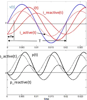
Figure 1 shows the traditional way of presenting the concepts of active and reactive power [5]. The upper part displays the instananeous line voltage (blue solid line) and the instantaneous current (red solid line) of a single phase of a power system. In this case, the current is lagging in time relative to the voltage with a phase angle φ. The total current can be understood as the sum of the active current component (red dotted line) that has no phase shift relative to the voltage and the reactive current (red dashed line) that is completely out of phase.
The lower part of the figure diplays the decomposition of the instantaneous single-phase power into components. The active power oscillates with twice the voltage fre-quency between its maximum value and zero, but never turns negative. The reactive power oscillates with twice the voltage frequency around zero. Its average is zero.
0 0
v(t)
i(t)
p(t)
p_acve(t)
p_reacve(t)
T
i_reacve(t)
i_acve(t)
φ
Fig. 1. – Upper part: Voltage (blue line) and decomposition of the total current (red solid line) into active current (red dotted line) and reactive current (red dashed line) of a single phase of a power system in arbitrary units. Lower part: Decomposition of the instantanous single-phase power (black solid line) into active power (black dotted line) and reactive power (black dashed line).
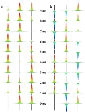
buildup of electric and magnetic fields, the reactive power flow in three-phase circuits corresponds to therearrangement of these fields.
Fig. 2. – Side view of Poynting vector envelopes in a balanced three-phase overhead line at different instants of the half period (frequency of 50 Hertz). The individual phases of the 380 kV circuit are 10 meters apart. For visualization, the radial width of the Poynting vector envelope was magnified by a factor of five. a) Purely active power flow. b) Purely reactive power flow. After ref. [6].
A first observation is that power does flow next to, but around the overhead lines. This is because the interior of conductors is on the same voltage and hence free of electrical fields. Second, as a consequence of its definition with a cross-product of electric and magnetic field, S =E ×H, the Poynting vector is strictly oriented in the direction of the overhead lines.
Z
LV
GI
V
LX=i L
ΔV
V
LI
V
GV
LI
V
Ga
b
ω
δ
ΔV
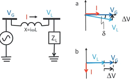
Fig. 3. – Left: Circuit representing a transmission line. Right: Phasor diagrams for active power transfer (a, top) and reactive power transfer (b, bottom).
Reactive power, in the right of the graph, oscillates back and forth in each phase. It is the power flux associated with the change of the energy stored in the electromagnetic fields of the components downstream from the present location. Its average across the three phases is zero, but it cannot be exchanged between the three phases due to the fixed orientation of the Poynting vector.
4. – Voltage angle and voltage drop
What determines the amount of power that is transferred by a transmission line? It is the voltage angle, the phase angle between the voltage vector at the sending and the voltage vector at the receiving end of the line. This is a consequence of the predominantly inductive character of overhead lines.
The left-hand part of fig. 3 shows the simplest possible circuit representing a trans-mission line. A synchronous generator supplies the sending end voltageVG; a loadZL sees the receiving end voltageVL. The line is represented by the self-inductanceLwhich is a lumped notation for the combined action of Ampere’s and Faraday’s law. The chang-ing magnetic field around the conductor induces a voltage along the conductor, that is phase-shifted by 90 degrees relative to the current. This is the physical reason for the importance of the voltage angle for the active power transfer.
As the active part of the transmitted power is carried by the current component that is in phase with the voltage and as any current passing over an inductance induces a voltage shifted by 90 degrees, sending end voltage and receiving end voltage must differ by a phase angle rather than in magnitude. This is visualized in the phasor diagram in the upper right of the figure. (Phasors are vectors in the complex plane that stand for the sinusoidal voltages and currents.) The active current being parallel with the voltage induces a voltage drop perpendicular to it and hence a shift in the angle.
line and is visualized in the phasor diagram in the lower right of the figure. The reactive current is perpendicular to the voltage, that is out of phase with it, it induces a voltage drop parallel to it and hence a reduction in the voltage magnitude.
5. – Frequency control
The frequency of interconnected power systems serves implicitly as a sensor and a communication signal. It helps to maintain the balance between the demand for power and the power supply. Demand and supply have to be equal at all times, if the instana-neous demand exceeds the supply, the system frequency will start to drop; if the demand falls below the supply, the system frequency will start to rise. The system frequency is to a good approximation the same in any point of the grid. It is a global quantity.
The stability of the frequency has its physical origin in the operation of the syn-chronous generators. They provide the bulk of the power supplied to the grid. The power that a single generator feeds into the grid is a function of the angle between the rotor and the stator whose field is rotating with the grid frequency. The more mechanical torque the turbine provides to the rotor shaft the larger will be the angle between rotor and stator field and the more active power the generator will feed into the grid.
Synchronous generators are controlled according to their role agreed with the overall system operator. Most generators contract the total of their output per each hour in the day-ahead market. In that case, at the start of the hour, they ramp up the rotor angle by increasing the mechanical power driving the rotor, for example by opening the valve that governs the amount of steam expanding in the steam turbine which in turn requires more steam to be produced and more fuel burnt in the steam generator. For the rest of the hour they maintain this output.
A few of the power plants take the role of the frequency control and act as a reserve. The power plants for primary frequency control act as a proportional controller and increase their output in proportion to the negative deviation of the system frequency from 50 (or 60) Hertz. They alsodecreasetheir output in proportion to the positive deviation of the system frequency. The primary frequency control ensures the stability of the system frequency even though the actual instantaneous power demand will always deviate somewhat from the predictions of the demand the day before. The primary frequency control is also seized such that it is able to deal with sudden power plant outages.
Other power plants are contracted for secondary control. They act as an integral controller and are powered up if the frequency is outside the target range for 30 seconds or longer. In such situations the secondary control plants gradually replace the power output of the primary control plants which are typically unable to maintain their output for long. Thetertiarycontrol power plants are the last reserve for maintaining the system frequency.
is 10 milliseconds, times the rated power of the power system. The complete rotational energy of the synchronous generators is typically about five seconds times the rated power of the power system. Such fragile system can only be kept stable by exploiting the property of the global system frequency to carry the information of the instantaneous active power balance.
6. – Voltage control
The voltage is, in contrast to frequency, a local quantity. We understand from the discussion in sect.4that any transfer of power, but particularly the transfer of reactive power, leads to a drop in the magnitude of the voltage. To put it in another way, the voltage is pulled down at a point of consumption and lifted upwards at a point of supply. In physical terms, this is a consequence of the absorption of power in the parasitic inductances of the power lines and other components and a consequence of the dissipation of electric power in the resistance of the power lines. Standards require that the voltage has to be maintained within plus and minus ten percent of the nominal value. The voltage is primarily controlled by adjusting the rotor excitation of the syn-chronous generators [2]. It is the major advantage of synsyn-chronous generators that they can control the balance of active and reactive power independently from each other. While supplying the scheduled active power, synchronous generators adjust the amount of reactive power injected into or extracted from the system and thus control the voltage at their point of supply.
The voltage drop limits the amount of power that can be transferred over a power line. In fact it is the main limitation for transmission distances between 80 and 320 kilometers. Transmission over longer distances than 320 kilometers is constrained by the stability of the voltage angle, transmission over shorter distances than 80 kilometers by thermal considerations.
The transfer of reactive power from the point of supply is a burden for the power system. It creates additional losses and leads to a deviation of the voltage from the norm at the point of the load. For this reason, a variety of equipment types has been devised to contribute to the local voltage control. Most intuitive is the use of capacitors to compensate for the inductive nature of lines and transformers. Shunt capacitors are connected between line and ground and serve as a storage of the energy used in the reactive power flow. In contrast to the synchronous generators, shunt capacitors supply the reactive power close to the load and avoid the transfer of reactive power over long distances.
reactive power between the three phases of the system, providing the shortcut for the power flow that is prevented by the nature of the Poynting vector.
7. – Integration of renewables
At this point we may wonder how the grid can live with a massive integration of power from wind and sun. The grid can live with it indeed — if the right complementary measures are taken. One way to organize the topic is to go from short time scales to long time scales of the implied energy storage. We start with voltage control, that is the storage of energy in electromagnetic fields for half an oscillation period; and we end with a comment on seasonal time patterns.
Wind turbines and photovoltaic cells are put into places that were not intended to be points of supply at the moment of the power system planning. As we know from the earlier discussion, the voltage at those places will be lifted upwards during the times of power supply. A typical challenge is the occurence of overvoltages in residential neigh-bourhoods with many solar panels during noon.
Fortunately the dominant factor in voltage control is the balance of reactive power, and here a solar inverter can help. It can not only convert the direct current of solar cells into alternating current and feed it into the grid, it can also supply these alternating currents in such a way as to look to the grid like a synchronous generator. A suitably dimensioned inverter is able to inject or absorb reactive power while doing his main job and maximizing the active power supplied to the grid.
Wind and sun are also able to contribute to primary reserve. This is the time scale of seconds and minutes. By operating slightly below the maximum output, additional power is instantaneously available — though with the corresponding penalty for the total energy yield.
Weather fronts move with typical speeds. The ramp rates of wind power and the sudden shutdown of wind power during storms define the required amount of comple-mentary fast gas power plants that are able to adapt their output on the time scales of minutes.
Traditional fossil power generation is essentially a conversion from stored chemical energy — gas, oil, coal — into electric power. In contrast to this, wind power and power from the sun are a conversion from an instantaneous natural stream of available energy. Their essence is the contingency and the fluctuation. The grid provides a statistical averaging of this energy harvesting. The more extended the grid, the more pronounced the averaging effect. This can be taken as a kind of virtual energy storage of the order of one or two hours. Wind looses its spatial correlation completely beyond distances of 1500 kilometers.
REFERENCES
[1] Ohler C.,Europhys. News,44(2013) 27.
[2] Ohler C.,Eur. Phys. J. Web of Conferences,54(2013) 01008.
[3] Mohan N.,Electric power systems: a first course(Wiley, New York) 2012. [4] Kundur P.,Power system stability and control (McGraw-Hill, New York) 1994. [5] Elgerd O.,Electric energy systems theory (McGraw-Hill, New York) 1971. [6] Cakareski Z. andEmanuel A.,IEEE Power Engin. Rev.,19(1999) 46.