AJA method and AJA Canvas as a Design Tool for
Autonomous Operations
Marialena Vaagia1 , Esten Ingar Grotli1, Aksel Andreas Transeth1, Magnus Bjerkeng1, Fredrik Bakkevig Haugli1, and Gorm Johansen1
1 SINTEF Digital, Mathematics and Cybernetics; Trondheim, Norway; * Correspondence: marialena.vagia@sintef.no; Tel.: +47-94428563
Abstract:Several design methods and principles have been presented so far, in order to guide the design of autonomous operations. Putting the required efforts into learning and using the methods for designing autonomous operations is a daunting task. Experiences so far have shown that the use of methods meant to the help the design process are often ignored. One reason could be that the design guidelines are too complex and contain much information often not relevant for the project at hand, and therefore there is no easy way to distinguish what is important from what is not. This is an issue that needs to be solved with our approach. In this article, the Autonomous Job Analysis (AJA) method is presented. The proposed methodology is created in order to guide the design of autonomous operations in maritime systems by breaking them down in to sub-operations in order to reveal challenges, needs and limitations regarding autonomous behavior. The canvas contains the categories of the AJA method on a single page format -the canvas- and each category is supported with questions to be asked during the design procedure, as well as example answers. We will describe the AJA method and the AJA canvas in detail, and present a use case scenario of an autonomous operation in order to show how they can be applied. The particular use-case is the design of an autonomous operation for the detection, inspection and tracking of a waste water plume.
Keywords: Autonomy; LOA; design; swarms; underwater vehicles; marine; Autonomous Job Analysis; canvas
1. Introduction
Autonomous mobile systems are systems capable of reasoning about, and solving unstructured problems without the direct control of humans and are central to future exploration of the ocean space. Although there have been several definitions of the word autonomy throughout the years, we will be following the one presented in [1]: the ability of an engineering system to make decisions about its own actions while performing a task, without the direct involvement of an exogenous system or operator. We have to emphasize that autonomy is not all or none, but can vary across a continuum of intermediate levels, between fully manual performance and fully autonomous conditions at the two extremes [1], [2]. Particularly well known examples of projects with a high Level of Autonomy (LOA) [3] include the Mars space missions [4] and self-driving cars [5]. The possibility of increasing the usage of autonomy in maritime industries is considered crucial especially in industries like oil and gas, waterborne transport [6], [7],[8] and fisheries and aquaculture [9]. Futuristic visions of those industries include trans-oceanic unmanned cargo ships [6]; inspection, maintenance and repair (IMR) [24] of subsea oil- and gas infrastructure carried out by permanently residing autonomous underwater vehicles [10], [11] unmanned airplanes surveilling the oceans for ice-bergs threatening oil- and gas installations [12]; IMR of aquaculture fish farms at exposed locations using autonomous underwater vehicles [13],[14]. By itself, the design of such types of autonomous operations and systems is a complex task [7]. Any type of method that could offer the users a guideline regarding the autonomous functionalities that they have to organize would be of a great help. Under these assumptions, we developed the Autonomous Job Analysis (AJA) method [15] that is a structured approach for the design of autonomous operations. AJA is based on principles used in Hierarchical Task Analysis (HTA) [16],
[17], [18] and has the underlying principle of breaking down a task into individual elements and study them. Among the different problems one has to face in the task analysis procedures, is deciding what to describe and to what level of detail. This can be challenging enough since it is not always obvious how to break down an operation in order to accomplish a representative analysis. The AJA method is one of the suggested methods in the SEATONOMY methodology [19], which provides a structured approach for design, development and validation of mobile autonomous maritime operations and systems. An analytical and descriptive overview of the SEATONOMY methodology can be found in [19]. In order to further facilitate and enforce the AJA methodology that is already proposed, we are in addition proposing a single page AJA canvas. The canvas idea is based on the business model canvas [17],[20],[21] approach and the scope is to gather the essential information needed for the design of an autonomous operation into a single page document. This facilitates the applicability of the method and gives the users the possibility to carefully design and analyze the operation in a structured manner. In order to ease the understanding of the presented method, we have illustrated it through application on a test case study referred to as "storyboard" which concerns the detection of an underwater waste plume with the usage of a swarms of autonomous underwater vehicles (AUVs). Finally, we present an additive tool, that can help with the design of autonomous operations, which we call the "requirements table". This table, gathers the functional requirements of the operation to be analyzed and gives the designers an extra tool in the organization phase. The outline of the current paper is as follows: In Section 2 we will describe the AJA method, in the sequel the AJA canvas will be presented in Section 3, and the Requirements table theory is presented in Section 4. The results of the test case scenario are presented in section 5, while the conclusions are drawn in section 6. In the Appendix A, the full tables regarding the AJA analysis and the requirements table are presented.
2. Results
2.1. Requirements and advice to be followed
The AJA method is based on principles used in HTA which is considered as the "best known task analysis technique" [18]. The main purpose of the AJA method is to aid the design of autonomous marine operations by uncovering the overall operational modes and design challenges as well as needs and limitations related to autonomous behavior by breaking down operations into sub-operations and tasks and analyzing these individually. As a result, the method facilitates a common understanding between all stakeholders. For an autonomous operation related to oil- and gas the stakeholders could for instance be:
• An oil company that needs the operation to be executed.
• An oil service company carrying out the physical operation.
• A company designing the autonomous operation.
• One or more companies developing the system needed to execute the operation.
There is not always a distinction like this, and the stakeholders could also all be from the same company. AJA may not only be used when designing new autonomous marine operations, but also for analyzing existing marine operations. AJA can reveal possible design flaws or be used as a tool for design improvements. AJA is a team effort and requires close cooperation between people with different competence and backgrounds for best results. This will help designers in defining the correct goals and reach the desired result. Prior to AJA a unified understanding between all stakeholders of what the AJA is trying to achieve should be established. This could for instance be achieved by distributing a brief description of AJA, containing the main elements from this section.
2.2. Guidelines to be followed
which is “a structured and systematic examination of a planned or existing process or operation in order to identify and evaluate problems that may represent risks to personnel or equipment, or prevent efficient operation”[18]. The main goal of the AJA meeting is to gather and share all available information concerning the operation in question through cooperation between stakeholders. This information is then structured and gathered in a detailed list for sharing. The information can include, but is not limited to, constraints, limitations, restrictions regarding the software/hardware, money, human resources, and any kind of available information that can affect the design or the implementation of the operation. A proposed agenda for the meeting can be as follows:
2.3. Subsection
2.3.1. Subsubsection
Bulleted lists look like this:
• First bullet
• Second bullet
• Third bullet
Numbered lists can be added as follows:
1. Introduction and presentation of participants. 2. Presentation of the main goal(s) of the operation. 3. Presentation of the AJA method.
4. Recapitulate the context definition and operation concepts. 5. Perform AJA (as far as possible).
6. Agree on further actions.
The meeting is driven by the moderator who is responsible for:
• Introducing the method to the client.
• Leading the discussion.
• Ensure completeness of the analysis.
The moderator could be from the team designing the operation, or hired from an external company specializing in leading these kinds of meetings. It can for instance be desirable to use an independent third party which does not favor either of the stakeholders. The secretary is responsible for:
The secretary is responsible for:
• Recording the discussion.
• Version control of the AJA table/flow chart.
The AJA table consist of a series of questions to be answered, and is described in detail in Section 2.3. The meeting participants should be experts within various aspects of the operation. Meetings including a large number of participants tend to become inefficient and hard to manage. If it is likely that the total number of participants needed exceeds 8-10, then dividing into smaller meetings should be considered. The responsibilities of the participants are the same as for participants as HAZOP meetings, as described in [23]:
• Be active! Everybody’s contribution is important.
• Be to the point. Avoid endless discussion of details.
• Be critical in a positive way not negative, but constructive.
It is unlikely that all questions can be answered during a single AJA meeting even if the total number of participants is kept low. ’Further actions’ could therefore be to choose one or more responsible to actively seek out the relevant or missing information through experts or written material. The AJA table should be updated with this new information, or at least with reference to documentation available elsewhere, before it is distributed among the stakeholders. The person(s) responsible can be chosen from the operation design team, or from the client’s team. The client may have relevant experts in his/her company, even if these experts did not attend the AJA meeting. If a large operation is to be analyzed, it may be necessary to perform AJA over several meetings. This gives the opportunity to include new or additional experts to add different perspectives of the operations. It is important that new participants are brought up-to-date before the meeting in order not to waste time. In the beginning of the meeting the requirements/context specification should be agreed on.
The Autonomous Job Analysis consists of the following steps:
• Describe the main goal of the operation
• Divide into sub-operations based on e.g. sequence, parallel behavior or choices
• Answer the list of AJA questions described in Table 1.
• For each sub-operation, go to step 2) and repeat until the sub-operations become trivial tasks.
The following steps are required during post processing:
1. The details from the AJA meeting should be processed and distributed among the stakeholders. 2. The stakeholders give feedback for possible subsequent iterations.
Table 1.AJA Table Formulation.
ID Name Description
1 Description of sub-operation and corresponding goal
Give a short description of the sub-operation focusing on the goal without too much technical detail. Achievement of the goal should contribute to the achievement of a goal at a higher level, and eventually the main goal of the operation.
2 Communication Communication flow: What key
information needs to be communicated? Communication restrictions: What are the limitations?
3 Perception Which information about the
environment and the system itself must be available?
4 Success Criteria List design criteria which specify
whether the sub-operation has been achieved. This can for instance be performance specifications related to accuracy or time.
5 What can go wrong? Is there anything that can prevent the sub-operation from being successfully accomplished? Be specific about what characterizes abnormal behavior. 6 What is the operational safe state? Define what state or mode should the
system should go to, in order maintain the safety of the operation in a best possible way.
7 Human-Machine Interaction Describe the human-machine interaction. The interaction can be described in words, or with reference to some taxonomy for Levels of Autonomy, for instance as given in [1].
8 Other premises/requirements Describe other relevant premises for successful execution of the sub-operation.
9 Notes and comments Add comments that are relevant for the sub-operation, but are not captured by the previous questions in the table.
2.4. The AJA Table formulation
2.jpg
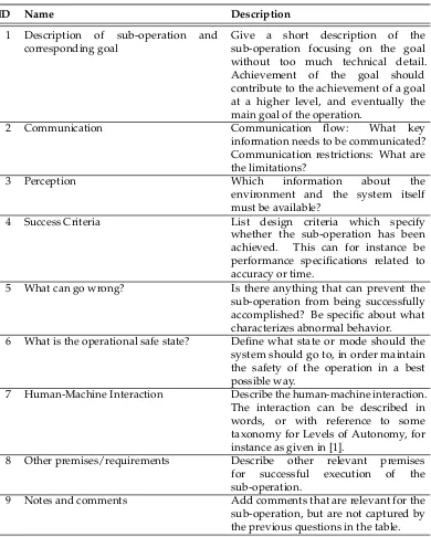
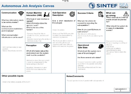
Figure 1.The AJA Canvas
possible, and a higher level of autonomy is required. Depending on the operation and the available information, the table can be modified by adding or removing categories as deemed necessary.
2.5. Output
The output is a structured description and breakdown of the operation where each sub-operation is individually analyzed based on technological and operational constraints uncovered at the AJA meeting.
3. The AJA Canvas
in order to keep similar categories on the same side of the canvas (left or right). The "Sub-Operation Description" gives central information on the sub-operation at hand, whereas the right- and left hand side details this sub-operation. At the bottom, the users can also note the number of the sub-operation the canvas is representing in order to relate sub-operations and their corresponding canvases. All the categories of the canvas are identical to the categories that appear in the AJA table just giving the user the possibility to have all the notes that refer to one sub-operation gathered on a single piece of paper. In addition, the canvas is giving some example answers to the AJA questions. In order to fill out the canvas the user should print out one copy for each sub-operation to be treated, and use it in meetings between customers, operation designers and field experts (e.g. experts in the area of risk management, robotics, autonomy, instrumentation etc.). This way they can jointly start sketching and discussing the autonomous operation. These meetings are referred to as AJA meetings [10].
4. Requirements Table
In addition to the AJA method the authors propose the creation of an extra table referred to as the "Requirements table" that can be used as an extra help in the analysis of the operation. This table can give the stakeholders an overview of what is expected from the different participants at the diverse stages of the operation. The information from the AJA Table can directly be used to create the Requirements table. To create the Requirements table one needs to follow the next steps:
1. Create the AJA tables using the described AJA method as described in Section 2.
2. Carefully analyze the AJA-tables to extract the requirements and write these requirements in an agreed upon format.
One has to decide wether to fpcus on the functional or the design decisions requirements. This means that, for example, one requirement can be that a certain vehicle shall be able to measure its own position, instead of specifying that it should be equipped with a certain (type of) sensor that would make it possible to measure this. One challenge that is encountered when working with specifying the requirements is to decide what level of abstraction to choose. This indeed is an important decision that needs to be made by the ones specifying the requirements for an autonomous operation. In the requirements table the use of the word “shall” denotes requirements that must be met. Use of the word “should” denotes requirements that are desirable and must be met unless justification is provided for an alternative. Use bold for "shall" and "should". Each requirement shall only contain one "shall" or "should". Use TBC (To Be Completed) or TBD (To Be Defined) in order to write precise requirements even though all details are not in place. For example: "Accuracy shall be TBD". Text in italic is used to separate comments, design issues and reasoning from requirements. This helps writing requirements short and precise and still the reader gets the context. The requirements are grouped according to the following definitions: VEH – Vehicle requirements. That is AUVs, ROVs and ASVs. HMI – User interface and control station requirements. COM – Communication requirements. INT-Distributed intelligence, typically mapping, cooperation algorithms etc. GEN – General requirements that does not fit into any of the other categories. Req. No.: Requirement numbers shall start with the group followed by a unique number. Derived requirements (if any) have an additional number. For example: GEN-1-1 is the first derived requirement to requirement GEN-1. Requirements numbers may be changed in final version of documents. Letters may be used in early document versions in order to present requirements in a logical order. For example GEN-1, GEN-1a, GEN-2, GEN-2a, GEN-2b, GEN-3 etc.
5. Use-case" Detection, inspection and tracking of plumes
3.jpg
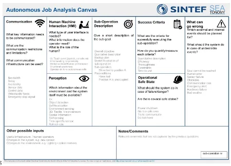
Figure 2.Support vessel deploying AUVs
operation, the following number of vehicles were available: AUV: 3+, ROV:0, ASV:1, Support vessel:1. What is the role of each kind of vehicle?
AUV: The AUVs will track the plume in order to locate and quantify the scope of the pollution. The more UAVs that are used, the better the resolution of the plume measurements will be. This is especially true when chemical sensors are used instead of cameras, as they can only detect the pollution level in a single point. An additional benefit of having multiple AUVs is that each AUV will have to be less mobile in order to cover the entire plume in satisfactory detail. This will in turn reduce the battery drain and allow for a longer operational time. ASV: ASV is a relay in order to ease all underwater to surface communications.Support Vessel: The support vessel will transport all the required equipment, robotic vehicles and will supervise all the vehicles that take part in the operation. During dredging both area surveillance and tracking of plumes are relevant. For oil spills, other strategies can be used in order to detect the source of the oil spill.Stage 0: Mission planning Actors: Command and Control Centre Actions to be done: Planning and conditions for re-planning. Stage 1: Deployment of AUV’s and ASV’s
Actors: Support vessel, AUVs Actions to be done: The AUVs are deployed as near the plume, or potentially the outlet as possible. If necessary one or more ASVs are used for communication between the support ship (or onshore) and the AUVs.
Stage 2: Detecting and tracking the plume
Actors: Support vessel, AUVs Actions to be done: Some or all AUVs are able to detect the plume by using appropriate sensors. The AUVs could swim in and out of the plume and cooperate with each other’s in order to follow and measure the plume. If a vulnerable area needs to be surveyed, for example during dredging, a simplified strategy could be used.
Stage 3: Share information between AUVs
Actors: Support vessel, AUVs Actions to be done: Each AUV reports position and concentration to other AUVs in order to autonomously spread themselves around the plume and also to retransmit information to the surface (see stage 4).
Stage 4: Share information to the surface
4.jpg
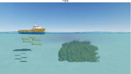
Figure 3.AUVs detecting and tracking the plume
via a high bandwidth communication link. By retransmitting data between AUVs, it is more likely that all information can be transmitted to the surface vehicle.
Stage 5: Send information to the Support vesselActors: Support vessel, AUVs Actions to be done: Data is sent from the ASV to the Support vessel or onshore via RF-link. The possibility of local data storage on AUVs or ASVs and the possibility to ask for retransmission of data, will have to be decided upon.
5.1. AJA Table for the plume detection story board
5.jpg
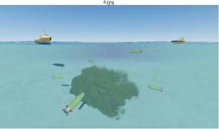
Figure 4.Information sharing between AUVs
6.jpg
7.jpg
Figure 6.RF Data transmission from ASV to support Vessel
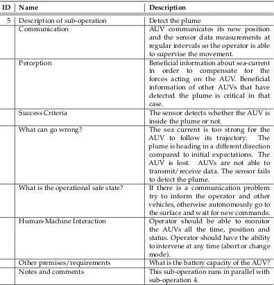
Table 2.Snapshot of the AJA Table for the presented storyboard sub operation 5.
ID Name Description
5 Description of sub-operation Detect the plume
Communication AUV communicates its new position
and the sensor data measurements at regular intervals so the operator is able to supervise the movement.
Perception Beneficial information about sea-current
in order to compensate for the forces acting on the AUV. Beneficial information of other AUVs that have detected the plume is critical in that case.
Success Criteria The sensor detects whether the AUV is
inside the plume or not.
What can go wrong? The sea current is too strong for the AUV to follow its trajectory. The plume is heading in a different direction compared to initial expectations. The AUV is lost. AUVs are not able to transmit/receive data. The sensor fails to detect the plume.
What is the operational safe state? If there is a communication problem try to inform the operator and other vehicles, otherwise autonomously go to the surface and wait for new commands. Human-Machine Interaction Operator should be able to monitor the AUVs all the time, position and status. Operator should have the ability to intervene at any time (abort or change mode).
Other premises/requirements What is the battery capacity of the AUV? Notes and comments This sub-operation runs in parallel with
8.jpg
Figure 7.Canvas Formulation for the plume detection storyboard
5.2. Canvas Formulation for the presented storyboard
As far as the AJA canvas example for the presented storyboard is concerned, because of page restrictions we present a canvas for sub-operation 5 only. The others, can be generated in a similar manner.
5.3. Requirements Table Formulation for the presented storyboard
Table 3.Snapshot of the AJA Table for the presented storyboard sub operation 5.
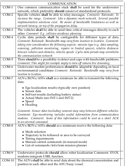
COMMUNICATION
COM-1 One common communication stack shall be used for the underwater network, which preferablyshouldconsist of standardized protocols. COM-2 Specific vehicles shallbe able to relay messages. Comment: Rationale: To
increase the range. Comment: Like a dynamic mesh network. Several possible implementation solutions exist. Be aware of bandwidth limitations as well as network latency, on top of the propagation delay.
COM-3 The vehiclesshallbe able to send time critical messages directly to each other. Comment: E.g. collision avoidance planning
COM-4 Cyclic data periods shall be configurable for different types of data. Comment: Rationale: Bandwidth may vary from location to location. Comment: taking into consideration the following aspects: mission type (e.g. data sampling, scanning, pollution monitoring, repairs in limited spaces), relative distances between vehicles and obstacles, vehicles speeds. Cyclic data periods may overwhelm the communication network
COM-5 Thereshouldbe a possibility to detect and cope with bandwidth problems. Comment: This might for example imply to turn off camera live streaming. COM-6 Underwater modem performancesshouldbe adaptable depending on local
environmental conditions Comment: Rationale: Bandwidth may vary from location to location.
COM-7 AUVs/ROVs/ASVsshallas a minimum be able to transmit the following data:
• Ego localization results (typically own position)
• Sensor data
• Self-test results (including battery status)
• Actual Mode (see INT-1 and INT-2)
• Speed
• Heading
Comment: Sensor data (including camera) may vary between different vehicles. Comment: Ego-monitoring includes useful information from communication modems. Comment: Some of this information could be sent as a short ACK to an external command.
COM-8 AUVs/ROVs/ASVsshouldas a minimum receive the following data:
• Mode selection
• Trajectory to be followed or area to be surveyed
• Timing requirements
• Manual control commands (in manual mode)
• List of commands/info from mission planner
COM-9 Underwater protocolsshouldallow robot localization Comment: EVOL modems integrate USBL function.
COM-10 The AUVsshallbe able to send data about the chemical concentration and position to each other and the ASV/buoy vessel.
6. Conclusion
canvas contains the categories of the AJA in a single page format, supporting each category with questions to be asked during the design procedure as well as example answers. The proposed method is tested in a use case scenario proposed which has the goal of detecting, inspecting, and tracking of waste water plumes. Examples of the utilization of the AJA table and the AJA canvas for the use case scenario are presented in the paper and in theAppendixAthe authors propose an additional tool, the requirements table that enforces the operation design procedure.
Appendix .1 Requirements Table Formulation for the presented storyboard
Autonomous Job Analysis
Main goal of operation: Storyboard: Detection, inspection and
tracking of Plumes
ID Question Answer
1 Description of sub-operation Current measurements and estimation
Communication NA
Perception Current measurements and a priori
knowledge
Success Criteria Good current estimates are necessary in order to estimate the speed and direction of the plume in order to create the trajectories.
What can go wrong? Too strong current to accomplish the
operation. Current estimates are wrong and thus trajectories are wrong.
What is the operational safe-state? NA
HMI A priori knowledge of current. Current
measurements. Other premises/ requirements
2 Description of sub-operation Mission plannins (Robots Point of view
Communication Ability to communicate with themselves and
the operator, distribution of the path to be followed, trajectory, or the pre-specified area they are going to move in, provide information regarding real time weather conditions (sea current etc.)
Perception NA
Success Criteria Hardware and Software are working fine,
and all test information has been transmitted and received correctly
What can go wrong? Communication/hardware/software
malfunctioning What is the operational safe-state? N/A
HMI Human should confirm that everything is
working properly Other premises/ requirements
Notes/comments This stage only takes into account what
Communication AUV communicates its new position at regular intervals so the operator is able to supervise the movement. AUVs also need to communicate with themselves.
Perception Own position.
Success Criteria AUV are at starting point with TBD meter
accuracy.
What can go wrong? Sea current too strong to arrive at position, collision between vehicles or outlet orifices, communication breakdown, AUV crash with ship or other infrastructure
What is the operational safe-state? Automatically go to the surface in case any error condition occurs, try to communicate any problem to the operator and other vehicles as well, turn off thrusters, and let AUV slowly ascend unless strictly below ship.
HMI AUV moves autonomously to starting point
of planned path under supervision of operator
Other premises/ requirements Notes/comments
4 Description of sub-operation Follow pre-planned AUV path
Communication AUV communicates its new position and
the sensor data measurements at regular intervals so the operator is able to supervise the movement.
Perception Beneficial information about sea-current in
order to compensate for the forces acting on the AUV.
Success Criteria The AUV follows the pre-defined trajectory
with an accuracy of 2 meters.
What can go wrong? The sea current is too strong for the AUV to follow its trajectory. The plume is heading in a different direction compared to initial expectations. The AUV is lost. One or more AUVs cannot find any plume in the specified time window, then move to sub-operation 3. AUV collision, AUVs are not able to transmit/receive data.
What is the operational safe-state? If there is a communication problem try to inform the operator and other vehicles, otherwise autonomously go to the surface and wait for new commands.
HMI Operator should be able to monitor the AUVs
all the time, position and status. Operator should have the ability to intervene at any time (abort or change mode).
Notes/comments The AUV should perform several rounds. That action is taking place for many AUVs in parallel.
5 Description of sub-operation Detect the plume
Communication AUV communicates its new position and
the sensor data measurements at regular intervals so the operator is able to supervise the movement.
Perception Beneficial information about sea-current in
order to compensate for the forces acting on the AUV. Beneficial information of other AUVs that have detected the plume is critical in that case.
Success Criteria The sensor detects whether the AUV is inside
the plume or not.
What can go wrong? The sea current is too strong for the AUV to follow its trajectory. The plume is heading in a different direction compared to initial expectations. The AUV is lost. AUVs are not able to transmit/receive data. The sensor fails to detect the plume.
What is the operational safe-state? If there is a communication problem try to inform the operator and other vehicles, otherwise autonomously go to the surface and wait for new commands.
HMI Operator should be able to monitor the AUVs
all the time, position and status. Operator should have the ability to intervene at any time (abort or change mode).
Other premises/ requirements What is the battery capacity of the AUV?
Notes/comments This sub-operation runs in parallel with
sub-operation 4.
6 Description of sub-operation Lost plume: Autonomously re-plan
according to other AUVs and measurements
Communication AUV communicates its new position and
the sensor data measurements at regular intervals so the operator is able to supervise the movement.
Perception Beneficial with information about sea-current
in order to compensate for the forces acting on the AUV. An alternative path for the AUV to follow needs to be available.
Success Criteria The path is re-planned and the AUV detects
the plume.
What is the operational safe-state? If there is a communication problem try to inform the operator and other vehicles, otherwise autonomously go to the surface and wait for new commands.
HMI Operator should be able to monitor the AUVs
all the time, position and status. Operator should have the ability to intervene at any time (abort or change mode).
Other premises/ requirements What is the battery capacity of the AUV? Does any alternative path exist?
Notes/comments It can run in parallel for many AUVs. At
least one AUV needs to have detected the plume the last TBD minutes, or return to sub-operation 5.
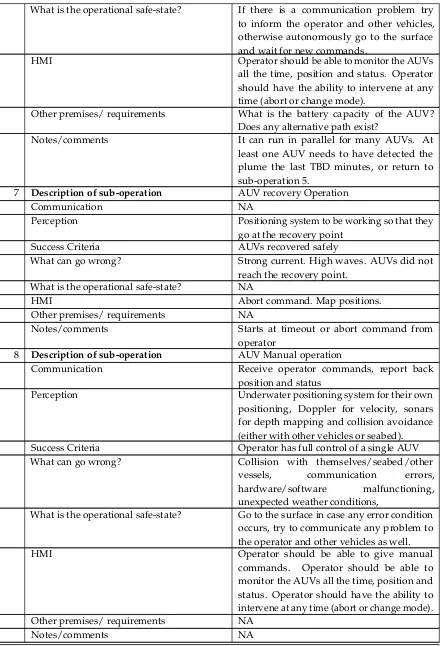
7 Description of sub-operation AUV recovery Operation
Communication NA
Perception Positioning system to be working so that they
go at the recovery point
Success Criteria AUVs recovered safely
What can go wrong? Strong current. High waves. AUVs did not
reach the recovery point. What is the operational safe-state? NA
HMI Abort command. Map positions.
Other premises/ requirements NA
Notes/comments Starts at timeout or abort command from
operator
8 Description of sub-operation AUV Manual operation
Communication Receive operator commands, report back
position and status
Perception Underwater positioning system for their own
positioning, Doppler for velocity, sonars for depth mapping and collision avoidance (either with other vehicles or seabed).
Success Criteria Operator has full control of a single AUV
What can go wrong? Collision with themselves/seabed/other
vessels, communication errors, hardware/software malfunctioning, unexpected weather conditions,
What is the operational safe-state? Go to the surface in case any error condition occurs, try to communicate any problem to the operator and other vehicles as well.
HMI Operator should be able to give manual
commands. Operator should be able to monitor the AUVs all the time, position and status. Operator should have the ability to intervene at any time (abort or change mode).
Other premises/ requirements NA
Notes/comments NA
TableA2shows an example of a requirements matrix. This table is an example that has been created for the given storyboard gien with information from AJA.
Req. no. Description Comment
Vehicle VEH-1 AUVs/ROVs/ASVs shall have the
ability of ego-localization with accuracy minimum TBD horizontally and TBD vertically. Comment: The accuracy will probably be given by the equipment available, not by demonstrator needs.
VEH-2 AUVs/ROVs/ASVs shall detect and report internal faults and error states. Comment: Battery status included. Comment: Self-test functions may vary between units. Comment: Reporting can be done with varying level of detail and message priority depending on error criticality. VEH-3 AUVs/ROVs/ASVs shall react to
internal faults and error states.Comment: Critical errors might invoke safe state. VEH-4 The middleware in the vehiclesshould
run on the same embedded computer with interface to the HW already on board the vehicles. Comment: Unless it is considered easier to integrate into the already existing computer when all aspects, also verification, are taken into consideration. VEH-5 All sensor datashouldbe stored in the vehicle for eventual retrieval after the mission is finished.Comment: Rationale is for backup in case of communication failure. VEH-6 The vehicleshallbe able to operate for
minimum TBD minutes.
VEH-7 All AUVs shall mount an acoustic modem.
VEH-8 Gateway buoy/ASV/support ship shall deploy both types of acoustic modems. VEH-9 At least one ROV should mount at least
one acoustic modem.
VEH-10 The AUVs shall be equipped with sensors for detecting the plume e.g. turbidity, salinity, temperature.
VEH-11 The AUVs shall support collision avoidance.
User Interface/Control (HMI) HMI-1 The operator shallbe able to interfere
with the operation.Comment: This could be to abort the operation, change modes etc. Modes are described elsewhere.
HMI-3 The age of the data shallbe presented or visualized to the operator.Comment: Design decision whether to use synchronized clocks and where data is to be timestamped. HMI-4 The operatorshallbe given a warning if
an abnormal situation occurs.Comment: Could be an alarm and/or a visual indication. HMI-5 The operator shall see the vehicle
positions in a sea map.
HMI-6 The operator should be able to collect data from vehicles manually after the operation. Comment: Might not be necessary to implement for the demonstrators.
HMI-7 It should be possible to use data retrieved from local storage together with real time collected data. This means they should have the same format and meaning. Comment: See VEH-4 Comment: For example to present all data collected inside the same map. Comment: Might not be necessary to implement for the demonstrators.
HMI-8 The operator shall be able to configure/change the safe state of each vehicle.Comment: see INT-7 HMI-9 The operatorshallbe able to configure
the battery threshold. Comment: See INT-5
HMI-10 The operatorshallbe able to configure what information/data is presented in the HMI.
User Interface/Control (HMI) COMMUNICATION (COM) COM-1 One common communication stack shall
be used for the underwater network, which preferably should consist of standardized protocols.
COM-2 Specific vehiclesshall be able to relay messages.Comment: Rationale: To increase the range. Comment: Like a dynamic mesh network. Several possible implementation solutions exist. Be aware of bandwidth limitations as well as network latency, on top of the propagation delay.
COM-4 Cyclic data periodsshallbe configurable for different types of data. Comment: Rationale: Bandwidth may vary from location to location. Comment: taking into consideration the following aspects: mission type (e.g. data sampling, scanning, pollution monitoring, repairs in limited spaces), relative distances between vehicles and obstacles, vehicles speeds. Cyclic data periods may overwhelm the communication network
COM-5 Thereshouldbe a possibility to detect and cope with bandwidth problems. Comment: This might for example imply to turn off camera live streaming.
COM-6 Underwater modem performances shouldbe adaptable depending on local environmental conditions Comment: Rationale: Bandwidth may vary from location to location.
COM-7 AUVs/ROVs/ASVsshallas a minimum be able to transmit the following data: - Ego localization results (typically own position) - Sensor data - Self-test results (including battery status) - Actual Mode (see INT1 and INT2) Speed -HeadingComment: Sensor data (including camera) may vary between different vehicles. Comment: Ego-monitoring includes useful information from communication modems. Comment: Some of this information could be sent as a short ACK to an external command.
COM-8 AUVs/ROVs/ASVs should as a
minimum receive the following data: - Mode selection - Trajectory to be followed or area to be surveyed -Timing requirements - Manual control commands (in manual mode) - List of commands/info from mission planner COM-9 Underwater protocols should allow
robot localization Comment: EVOL modems integrate USBL function.
COM-10 The AUVs shall be able to send data about the chemical concentration and position to each other and the ASV/buoy vessel.
COM-1-RF One common communication stack shall be used for the in air network, which preferably should consist of standardized protocols.
COM-2-RF The communication subsystem shall support RF wireless communication infrastructure between Ashore Control Station (Command and Control Centre) and a ASV, Buoy or vessel.
COM-3-RF The communication subsystemshould support point to point/point to multipoint connection link
COM-4-RF The communication subsystem shall support simultaneous transmission of data at uplink and downlink.
COM-5-RF The communication subsystem shall support transmission of different data types.Comment: Data types could be video streaming (compressed video), data, mission commands
COM-6-RF The communication subsystem shall support IP protocol
COM-7-RF The communication subsystem should allow/provide mechanisms for configuration the Quality of Services (QoS) parameters.
COM-8-RF The communication subsystemshould encrypt all the communication signals COM-9-RF The communication subsystem
should support mobile and portable communications
COM-10-RF The communication subsystem devices should be modular and portable/transportable
COM-12-RF The communication subsystem should cover at least:
• ashore-vessel: TBD km range
• vessel-ASV/buoy: TBD km range
• ASV-surfaced AUVs and
buoy-surfaced AUVs: TBD m
Comment: to be defined and tested, some estimation would be (depending on installation on the different nodes and demo sites):
• ashore-vessel: 4-5 km range
• vessel-ASV/buoy: 2-3 km range
• ASV-surfaced AUVs and buoy-surfaced AUVs: 200 m
COM-13-RF The communication subsystem between Ashore Control Station and ASV/Buoy/vesselshould operate at different MHz frequency band. Comments: possible bands could be non-licensed 5.8GHz, 2.4GHz
COM-14-RF The communication subsystemshould support advanced technologies. Comments: these technologies could be advanced Multiple-Input Multiple-Output (MIMO), OFDM/OFDMA or diversity modes/technologies.
COM-15-RF The RF communication subsystemshall support data transmission from the ASV/buoy to ship.
Distributed Intelligence (INT) INT-1 The following general modes shall be
implemented in the AUVs:
• Manual mode
• Go to surface
• Go to safe state
INT-2 The following modes should be implemented in the AUVs:
• Stop/Hoover
• Go to Position
• Battery save mode.
Comment: Battery save mode is not necessary for the demonstration. It can encompass reduced speed, disabling of unused sensors etc.
INT-3 Upon loss of communication for TBD minutes, the AUVshallgo to safe state. Comment: This timeout should be configured by the operator.
INT-4 Upon loss of communication for TBD minutes, the AUV should search for a position where communication is possible.Comment: This timeout should be configured by the operator. Comment: This timeout should be shorter than that of INT-3. INT-5 Upon low battery, the AUV shall go to safe state. Comment: The battery threshold should be configurable by the operator. Comment: if the safe state does not entail going to the surface, the battery threshold should be such that the vehicle can go to the surface with the remaining energy when going to safe state.
INT-6 A timeout function activating safe state shallbe implemented.
INT-7 The safe state shall avoid damage to vehicle, other equipment and environment. Comment: Often safe state will be to go to surface and report position for retrieval, but this might vary depending on storyboard and environmental conditions. INT-8 Obstacle avoidance should be implemented if required sensors are available.
INT-9 The swarmshallbe able to determine the perimeter and movement of the plume. INT-10 The swarm shall be able to track and
follow the plume.
General (GEN)
GEN-1 The equipment shall satisfy
GEN-2 The systemshallas a minimum support the number of vehicles specified in the storyboard.
Table A2.A.2 Requirements Table Formulation or the storyboard.
Author Contributions: conceptualization, M. Vagia, E. I. Grøtli, A. A. Transeth, M. Bjerkeng; methodology,M. Vagia, E. I. Grøtli, A. A. Transeth, M. Bjerkeng; validation, M. Vagia, F. B. Haugli, G. Johansen; investigation,. Vagia, F. B. Haugli, G. Johansen; writing—original draft preparation, M. Vagia, E.I. Grøtli; writing—review and editing, M. Vagia, E.I. Grøtli, A. A. Transeth; supervision, G. Johansen; project administration, G. Johansen;
Funding:This methodology has been developed as part of the work undertaken for the EU-funded research project SWARMS (Smart and Networking Underwater Robots in Cooperation Meshes) ECSEL project number 662107.
References
1. M. Vagia, A. Transeth, and S. Fjerdingen, A survey on level of autonomy and adaptive automation. How much to automate? .Applied Ergonomics2015,53, 190-202.
2. K. Wrobel, System-theoretic approach to safety of remotely-controlled.Ocean Engineering,152,2018, 334-345. 3. T. Sheridan, Telerobotics Automation and Human Supervisory Control .MIT Press, Cambridge, MA1992. 4. http: //www.nasa.gov/missionpages/mars−path f inder/.
5. https: //www.google.com/sel f drivingcar/ .
6. Ø. J. Rødseth, B. Kvamstad, T. Porathe and H. C. Burmeister, Communication architecture for an unmanned merchant ship.MTS/IEEE Oceans conference2013.
7. M. Rausand and I. B. Utne, Dynamic risk assesment of marine systems,2015, ISBN:9781138028791. 8. Ø. J. Rødseth, From concept to reality: Unmanned merchant ship research in Norway.IEEE Underwater
Technology2017.
9. V. Chalkiadakis, N. Papandroulakis, G. Livanos, K. Moirogiorgou, G. Giakos, Designing a small-sized autonomous inderwater vehicle architecture for regular periodic fish-cage net inspection,IEEE International Confrence on Imaging Systems and Teechniques2017.
10. I. Schjølberg and I. Utne, Towards autonomy in ROV operations.IFAC papers Online2015, 183-188. 11. E. I. Grøtli, J. Tjønnås, J. Azpiazu, A. A. Transeth and M. Ludvigsen, Towards more autonomous ROV
operations: Scalable and modular localization with experiment data.IFAC Conference on Control Applications in Marine Systems2016,49, 173-180.
12. J. Haugen, E. I. Grøtli and L. Imsland, State estimation of ice thickness distribution using mobile sensors.
IEEE International Conference on Control applications2012, 336-343.
13. N. A. Stanton, Hierarchical task analysis: Developments, applications, and extensions.Applied Ergonomics
2006, 55-79.
14. K. Grythe, T. A. Reinen and A. A. Transeth, Autonomy levels versus communication in an underwater environment,Oceans 2015,2015.
15. H. V. Bjelland, M. Føre, P. Lader, D. Kristiansen, I. M. Holmen, A. Fredheim, E. I. Grøtli, D. E. Fathi, F. Oppedal, I. B. Utne and I. Schjølberg, Exposed aquaculture in Norway: Technologies for robust operation in rough conditions.”, In: Proc. of the MTS/IEEE OCEANS’152015.
16. E. I. Grøtli, M. Vagia, S. Fjerdingen, M. Bjerken, A. A. Transeth, E. Svendsen, and P. Rundtop, Autonomous Job Analysis: A Method for Design of Autonomous Marine Operations.MTS/IEEE Oceans Conference2015. 17. N., A., Stanton ,Hierarchical task analysis: Developments, applications, and extensions.Applied Ergonomics,
37,2006, 55-79.
18. J. Annett and K. D. Duncan, Task analysis and training design.Occupational Psycology,37,1967, 211-221. 19. B. Kirwan and L. K. Ainsworth, A guide to task analysis.Taylor and Francis,1992, ISBN: 978- 074840058. 20. E. I. Grøtli, T. A. Reinen, K. Grythe, A. Transeth, M. Vagia, M. Bjerkeng, P. Rundtop, E. Svendsen, Ø. Rødseth,
and G. Eidnes, SEATONOMY - why a methodology for design of marine autonomous operations is necessary.
21. E., I., Grøtli, M. Bjerken, M. Christian, P. Rundtop, M. Vagia, F. Bakkevig, A. A. Transeth, Canvas as a dessign for Autonomous perations: With application to net inspection of a sea based fish farm using an underwater vehicle.Oceans 2017,2017.
22. A. Osterwalder and Y. Pigneur, Business Model Generation: A Handbook for Visionaries, Game Changers and Challengers.Wiley,2010,ISBN: 978-0-470-87641-1.
23. https: //strategyzer.com/canvas/business−model−canvas.
24. I. Schjølberg, T. B. Gjersvik, A. A. Transeth, I, B, Utne, Next generation Subsea Inspection, Maintanance and Repair Operations.IFAC papers online,2016, 434-439.