IJEDR1503094 International Journal of Engineering Development and Research (www.ijedr.org) 1
Synthesis & Simulation Model of Parallel Lift
Controller Using Verilog
Mohd Sabir Siddiqui1 Kamil Hasan2
1 PG Student (M. Tech), Dept. of ECE, AFSET Faridabad, Haryana, India. 2 Assistant Professor, Dept. of ECE, AFSET, Faridabad, Haryana, India.
________________________________________________________________________________________________________
Abstract - Machines are made to reduce human efforts and to save one’s time. The machines are elegantly built to suit the formal surroundings. Thus machines were made according to the human need. The high growth of the semiconductor industry over the past two decades has put Very Large Scale Integration in demand all over the world. The basics of digital logic theory and techniques are easily understood by the design based on VLSI technology. These are the core fundamentals of the fast, high-speed complex digital circuits. As day to day the technology is gradually improving. So obviously the designs have to be made simpler for enjoying the benefits. To do that, a Three-Lift Controller is modeled. In the proposed design a VERILOG RTL code is developed to control the lift moment based on the request it will get. For that a finite state machine is developed to know from which state to state the controller is changing based on the requests from the end user. Lift is also called as Elevator or car. The design is based on the synchronous input which should be operating with a fixed sort of frequency. Finally the RTL is verified and implemented in Precision Synthesis Tool. In this work, the real-time three-lift controller will be modeled with Verilog HDL code using Finite-State machine (FSM) model to achieve the logic in optimized way.
Keywords - FSM, Controller, Elevator control.
________________________________________________________________________________________________________
1. INTRODUCTION
An elevator is defined as, “A machine that carries people or goods up and down to different levels in a building or mine”. While a standalone elevator is a simple electro-mechanical device, an elevator system may consist of multiple standalone elevator units whose operations are controlled and coordinated by a master controller.
Such controllers are designed to operate with maximum efficiency in terms of service as well as resource utilization. The Elevator Controller is a device used to control a lift motion and to indicate the direction of motion, and the present floor level, etc. The device control the lift motion by means of accepting the floor level as input and generate control signals (for control the lift motion) as output.
An elevator is a device designed as a convenience appliance that has evolved to become an unavoidable feature of modern day urban life. This project details the design of an elevator controller using VERILOG.
The Elevators/Lifts are used in multi store buildings as a means of transport between various floors. Elevator is a device designed as a convenience appliance that has evolved to become unavoidable features of modern day in urban life normally. The lifts are controlled by Microprocessor based systems, which are costlier. It is proposed to design a low cost and compact dedicated controller. The Elevator Controller is a device used to control a lift motion and to indicate the direction of motion, and the present floor level, etc. The device control the lift motion by means of accepting the floor level as input and generate control signals (for control the lift motion) as output. We developed a VERILOG code for three parallel elevator control system for the cases of elevator moving up and down. The design and simulation of the Elevator controller can be performed using VERILOG. Also the Timings of various signals can be verified. VERILOG is a hardware description language used in electronic design automation to describe digital and mixed-signal systems such as field-programmable gate arrays and integrated circuits. The key advantage of VERILOG when used for systems design is that it allows the behavior of the required system to be described (modeled) and verified (simulated) before synthesis tools translate the design into real hardware .VERILOG project is multipurpose. Being created once, calculation block can be used in many other projects. However, many formational and functional block parameters can be tuned that are capacity parameters, memory size, element base, block composition and interconnection structure.
2. PRINCIPLE OF ELEVATOR CONTROLLER
Elevator controller is an elementary system consisting of elevator serving 8 floors (including basement). The elevator car has a pair of control buttons (up / down) for moving the elevator up and down. The floors also have call buttons to call for the service of the elevator system. The following principles have been applied during the design of the elevator controller: The floors are defined as first floor and second etc.
A floor call is serviced using the elevator.
Upon arrival at a floor, the doors open immediately. 8 Floor buttons, from 0(Basement) to 7th floor
IJEDR1503094 International Journal of Engineering Development and Research (www.ijedr.org) 2 When you press a floor button (for this code, for simplification, only one floor at a time is supported) clock 2 counts
from 3 to 0 before the door closes and moves to the desired floor, which increments or decrements with each clock signal from clock 1. After reaching the desired floor, counter 2 counts from 3 to 0 again before the door opens.
Doors remain open before closure.
If an obstruction is detected when door is about to close, it remains open Each elevator car is treated as a sub-system controlled by the controller. Elevator Up / Down buttons are connected to elevator units.
Each door unit is treated as a subsystem controlled by the respective elevator car. Floor call buttons are connected to the elevator controller.
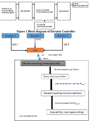
Figure 1 Block diagram of Elevator Controller
Figure 2 MODEL BLOCK DIAGRAM FOR THE ELEVATOR UNIT
3. STATE FLOW
Elevator Idling Block:
Three parallel elevator are signalling continuously signal acknowledge to the driver controller. At reset or after completion of task by each elevator, each of them will acknowledge an idle signal to controller.
User Signal Request Call:
A common input console is provided outside the elevator at every floor. When user press the up/down button from input CONSOL outside each level, signal request in send to controller acknowledging about what to instruct next.
User signal request call is stored in register upon which controller pass the signal request to elevators.
Depending upon current status of all three elevators, the elevator nearer to user input floor will act, and controller passes it control to that elevator. Rest of two elevators will have low priority and only the nearest elevator to user will assign the highest priority.
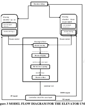
Our Verilog code has embedded algorithms about the nearest elevator selection as compare to reference floor. User Activated Block :
IJEDR1503094 International Journal of Engineering Development and Research (www.ijedr.org) 3 The status register related to user floor will update on each floor checking about the floor from where the call has made.
• Acknowledging the user in floor, elevator stops and idle state goes active.
Control system drives the door motor, hence opening operation is performed. Door barrier sensors and door opening/closing time is regulated by clock circuit used in our Verilog code.
• User will update the request final floor from inside the elevator; this will update the final requested floor register in our code. Acting upon value updated to reached the requested floor, control system will close the door and compactor algorithm in our code will do analysis about the direction and destination floor.
• On reaching to its final floor, elevator stops and current status register of elevator resets to idle state. Control system opens the door, thus user exits.
i. In idle state control feeds to closed loop checking again and again about input signal entered by user on every floor. Receiving any user signal the whole process of elevator will repeat till on completion of task.
Figure 3 MODEL FLOW DIAGRAM FOR THE ELEVATOR UNIT
4. RESULTS AND CONCLUSIONS
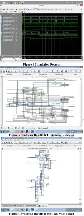
In this project the proposed design used Model Sim tool for Simulation and Precession Synthesis Tool for synthesizing the Design and target technology is Sparton3A device is 3a50tq144. Figure 4 shows the simulation result of the designed elevator controller and Figure 5 to 6 shows the RTL schematic of the design.
IJEDR1503094 International Journal of Engineering Development and Research (www.ijedr.org) 4
Figure 4 Simulation Results
Figure 5 Synthesis Results RTL Schematic design
Figure 6 Synthesis Results technology view design 5. REFERENCE
[1] Anne Millbrooke,Technological Systems Compete at Otis Hydraulic Versus Electric Elevators
IJEDR1503094 International Journal of Engineering Development and Research (www.ijedr.org) 5 [3] Samir Palnitkar, Verilog HDL,Pearson, Second Edition\7.1\pg 161.
[4] Samir Palnitkar, Verilog HDL,Pearson, Second Edition\6.1\pg 131.
[5] Mayke Predco, Hand book of Microcontroller (MC GrawHill,co,USA)1999.
[6] Yu Hai-bin, Zeng Pengo intelligent wireless sensor network system(M). Beijing: science press, 2006. [7] Zigbee standards organization, Zigbee specification, Zigbee document 05347r17, January17, 2008.
[8] S.Wei, L Li-Li, multi-parameter monitoring system for coal meine based on wireless sensor network technology proc. International IEEE conference on industrial mechatronics and automation, PP 225-27, 2009.
[9] Qiao ying-xu, design of wireless sensor network node based on tinyos operating system. The 3th international conference on computer science and education(C) 2008. 7 / 20 / - 1204.
[10] Jilin Li, “Status and Development trend of coal mine safety monitoring system” , journal coal technology, Hasbin, 2008(11), PP . 4-5.
AUTHORS
First Author – Mohd Sabir Siddiqui, PG Student (M. Tech), Dept. of ECE, AFSET Faridabad, Haryana, India.