Experimental Analysis of Bio-Oil from
Coconut Shell and Front by Continuous
Pyrolysis Process
Radhakrishnan C1, Karunaraja Natarajan2, Azhagendran K3, Mohanlal K4, Ponraj P5, Nivas R6
Assistant Professor, Department of Automobile Engineering, Dr.Mahalingam College of Engineering and
Technology, Pollachi, Tamil Nadu, India1
Junior Research Fellow, Department of Mechanical Engineering., Dr.Mahalingam College of Engineering and
Technology, Pollachi, Tamil Nadu, India2
UG Scholar, Department of Automobile Engineering,, Dr.Mahalingam College of Engineering and
Technology, Pollachi, Tamil Nadu, India3,4,5,6
ABSTRACT: The utilization of bio-mass materials as a renewable energy sources is attracting the global attention over the last two decades and this is much more predominant in countries where agricultural activities are abundant. A continuous type pilot plant for the production of bio-char and the down-stream products (bio-oil and synthesis gas) was designed, developed and analyzed. The pilot plant consists mainly of a rotary pyrolysis reactor, cyclone separator and a condenser assembly. Heating is done externally underneath the retort using an LPG stove, having provision for control-ling the heating rate. The generated bio-oil is directly condensed in water condenser method. Experiments were con-ducted with different types of bio-masses, varying the residence times and pyrolysis temperatures. The recoveries of bio-oil products obtained under different treatment conditions along with their characterizations are reported.
KEYWORDS: Continuous Pyrolysis, Bio-oil, Synthesis gas, Cyclone separator.
I.INTRODUCTION
Petroleum products such as fuel oil, gasoline or valuable chemicals are used in every aspect of life today. With rapid increase in world population, the demand for petroleum products is increasing day by day. But the world’s oil supply far too slowly in millions of years to be replaced at the rate at which it is being extracted. There are many solid biomass fuels suitable for gasification - from wood and paper to peat, lignite, and coal, including coke derived from coal.[1]
Availability of bio-mass in India is estimated about 500 million tons per annum, covering agricultural and forestry resi-dues, corresponding to a potential of about 18,000 MW. All of these solid fuels are composed primarily of carbon with varying amounts of hydrogen, oxygen, and impurities, such as sulfur, ash, and moisture. In creating shell gas for fuel-ing internal combustion engines, it is important that the gas not only be properly produced, but also preserved and not consumed until it is introduced into the engine where it may be appropriately burned.
A very important aspect of a pyrolysis plant is the bio-oil condensation process. Either single-phase or multi-phase pyrolysis oils may be collected during operation. [2]The use of wood gas oil generators need not be limited to transpor-tation applications. Most of the raw materials used in the production of biodiesel in these countries are soybean oil, canola oil, palm oil, and sunflower seed oil. Biomass conversion techniques including thermo-chemical and biochemi-cal conversion are employed for power generation and production of liquid bio fuels, chemibiochemi-cals and charcoal, which can be used as activated carbon.
heat are needed across the globe to reduce the environmental impact of traditional bio-char production practices. Castor oil which has been developed to overcome this problem is still not economically. [4] One new alternative raw material for the manufacture of biodiesel can be derived from agricultural wastes such as coconut husk and coconut shell that has undergone a process of pyrolysis at a temperature of 120 ˚C to 150 ˚C to produce liquid smoke. The recovery of bio-char and bio-oil products obtained under different treatment conditions along with their characterizations are re-ported. [5]A normative review of the literature describing the products, mechanisms and rates of carbohydrate
pyroly-sis is presented. The role of a complex sequence of competing solid and vapor phase pyrolypyroly-sis pathways is elucidated.
II. RELATED WORK
For each experimental run the experimental conditions such as weight of the initial biomass sample, reactor temperature, nitrogen flow rate, velocity of the screw are defined at the start. Biomass is firstly milled and completely dried. An initial sample is weighed with the pre-defined weight and placed in a proper enclosed glass flask apart from the reactor. The reactor temperature is set starting the burner where the LPG is used and the reactor eventually heats up and the temperature starts to increase where it is noted in the display by the function of temperature sensor. Pyrolysis process starts to take place where the temperature and time is noted when we receive bio-char through the collector. In this pyrolysis process the condensable gases are sending to the condenser through iron pipes, when the gas reaches the condenser particular gases are condensed to get pyrolytic oil which is called as bio-oil. Finally we get bio char, bio-oil and syn gas as the bio products after the pyrolysis of respective biomass.
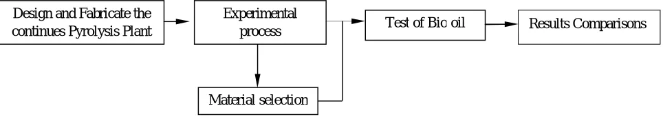
Figure. 1 Methodology flow chart
A pyrolysis unit typically consisting of a reactor, cyclone separator, condenser and related piping required for the downstream processing will be designed and fabricated. Step by step works shown in figure 1.
A continuous screw type reactor with provision for heating extremely using LPG will be developed. The cyc-lone separator is designed to separate the bio-char from the pyrolysis vapors.
The coiled type water coolant condenser facilitates separating the bio-oil from syn gases. The unit is provided with a Hooper which will control the quantity of bio mass entering the reactor. A pre processing unit for the size reduction of various bio masses is also planned, since the particle size of the bio mass feed material is about 10mm.
2.1.Modelling: The figure 2 shows that modeling of the profile is done using solid works13. The conventional designed model is various profiles have been generated as the same area is selected for other profiles. The dimensions are carried on millimeter format. The various parts of reactors to fix with face intersections.
Design and Fabricate the continues Pyrolysis Plant
Experimental
process Test of Bio oil
Material selection
Figure. 2 Research setup Modeling done by solid works 13
2.2 Pyrolysis Process: The pyrolysis experiments were conducted in a rotating drum reactor equipped with a sweep gas (nitrogen) connection. The reactor was heated externally by LPG gas sources. And the effect of reaction tempera-ture, the effect of flow rate of N2 and the effect of particle size, the following parameters considered by the pyrolysis process.
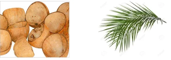
2.3 Raw Material Preparation: The figure 3 (a),(b) shows that the Preparation of raw materials for the manufacture of liquid smoke each as much as 20 kg of coconut shell and coconut husk and 10 kg of coconut munch that has been dried until the moisture content reaches 8-10%.After drying, the samples that are large cut into small pieces with a size of 1 inch length which can facilitate the combustion process. Samples were dried and reduced the net that has been inserted into the pyrolysis cylinder.
Figure.3 selecting materials (a) coconut shell (b) coconut front
2.4 Combustion (Pyrolysis): From the bottom of the combustion chamber ignited a fire that burned the pyrolysis, by heating the biomass in low/no oxygen environment. The absence of oxygen prevents the combustion. The smoke gen-erated will flow into the pipe condensation. The burning of the pyrolysis tube performed three replicates of each ma-terial. The drum contains screw type (helix) of formation and driven by the motor.
IV. RESULTS AND DISCUSSIONS
3.1 Yield of Bio oil: Yield of products from pyrolysis varying with temperatures by control the flow of gas by using regulator valve. The combustion chamber temperature between 200˚C - 250˚more char, while temperature above 250˚C
-300˚C favors the yield of oil and gases. The yield percentage of bio-oil calculated by using equation (1).
Yield (%) = amount of material pyrolysis (kg) / the resulting bio oil (kg) 100% …….. (1)
We have taken bio-oil from the sample product of coconut shell and front. The initial we have taken coconut shell as bio-mass to cut it to 1 inch length and measured initial weight of 2 kg’s and feed in to the chamber at the temperature of 230˚C we can get char about 1.8 kg’s at the time of 16 min as wheal as taken from the bio-oil at 4.98 kg’s.
As same as coconut front also, but the time taken from the char was within 10min and quantity of oil is more than co-conut shell 5.46 kg’s. The percentage of bio-oil yield from the coco-conut shell was 41 and coco-conut front 32.
Figure.4 collecting bio oil (a) coconut shell (b) coconut front
In this pyrolysis process the condensable gases are sending to the condenser through iron pipes, when the gas reaches the condenser particular gases are condensed to get pyrolytic oil which is called as bio-oil. We have experimented 1 kg of biomass (coconut biomasses) in the pyrolysis reactor and we have collected 0.6 kg of bio char and approx. 300-400 ml of bio-oil.fig 4 shows the collecting bio oil from coconut shell and coconut front.
3.2 Physical Properties: Final product of bio-oil obtained from pyrolysis process was taken and its physical properties were tested. The measurable properties of bio-oil (viscosity at 40˚C, calorific value (Kcal/kg) and moisture content of oil) as show table no 1.
Materials Samples Viscosity@40˚c Calorific Value (Kcal/kg)
Moisture %
Kinematic Dynamitic
Coconut shell 17.6Cst/s 18.37mPa.s 4456.6 21.3
Coconut front 17.8Cst/s 18.48mPa.s 4616 23
Physical properties were determined for the bio-oil using the American Standards for Testing and Materials (ASTM). The physical, chemical properties and calorific value of the bio-oil obtained under optimum conditions are given in Table no 1.
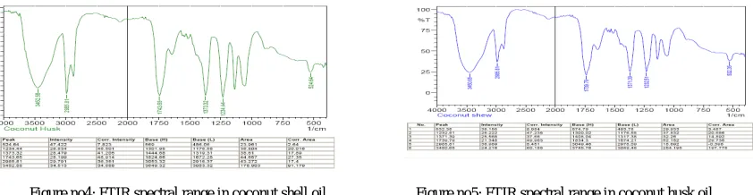
3.3 FTIR: Fourier transforms infrared spectroscopy (FTIR) is a technique which is used to obtain an infrared spectrum of absorption, emission, photoconductivity or Raman scattering of a solid, liquid or gas. An FTIR spectrometer simul-taneously collects high spectral resolution data over a wide spectral range.
Figure no4: FTIR spectral range in coconut shell oil Figure no5: FTIR spectral range in coconut husk oil
A good example is the CH set of vibrations, observed in the hydrocarbon spectra, and in virtually all organic compounds. Here, the simple CH stretching vibrations for saturated aliphatic species occur between 3000 and 2800 cm-1, and the corresponding simple bending vibrations nominally occur between 1500 and 1300 cm-1. As show in figure number 4 and 5.
No Peek Intensity Corr.Intensity Base(H) Area
1 532.35 38.155 8.984 574.79 3.487
2 1232.5 25.222 47 1300.02 20.686
3 1371.3 25.568 37 1408 14.89
4 1739.7 21.348 49 1834 29.73
5 2985.8 36.989 5.451 3049 -0.398
6 3450.6 24.216 60.185 3745.76 198.77
No Peek Intensity Corr.Intensity Base(H) Area
1 532.35 48.155 7.984 486.79 2.6487
2 1234.5 26.222 46 1176.02 20.016
3 1373.3 28.568 41.205 1319 17.89
4 1743.7 28.348 48.914 1672.28 27.73
5 2985.81 29.989 35.451 3049 17.398
6 3454.6 34.216 34.185 3649.76 91.77
V. CONCLUSION
Bio-Oil was produced under the continuous type of pyrolysis (absence of oxygen) by selecting coconut shell and coconut front as a biomass. A biomass product was fed into the pyrolysis chamber and LPG gas was used to fire the bottom surface of the chamber. The chamber was heated and reaches the temperature of 150˚C and above. The supply of biomass feed into the chamber to measure initial and final weight necessary for calculating bio-oil quantity.
The experiment was conducted by using coconut shell as biomass gets the Bio-oil of 600 ml out of 2kgs of
biomass as input. Similarly for coconut front gets the Bio-oil of 435 ml out of 2kgs of biomass as input. The temperatures noted are 250˚C for the two biomass products. For blending with diesel the kinematic viscosity and
dynamic viscosity for two samples namely coconut shell and coconut front founds to be less than the standard value. Hence other biomass products can be experimented for effective blending with diesel.
.
ACKNOWLEDGEMENTS
The financial support by the Dr.Mahalingam College of Engineering and Technology, Pollachi, Tamil Nadu. For this study in the frame work of the In-house R&D project on “Design and development of a Pilot plant for the production of Biochar and bio-fuels” is gratefully acknowledged.
REFERENCES
[1] Balat, M. An overview of the properties and applications of biomass pyrolysis oils. Energ Sources Part A 2011, 33, 674–689. [2] Chiaramonti, D.; Bonini, A.; Fratini, E.; Tondi, G.; Gartner, K.; Bridgwater, A.V.; Grimm, H.P.;Soldaini, I.;Webster, A.; Baglioni, P. Development of emulsions from biomass pyrolysis liquid and diesel and their use in engines—Part 1: emulsion production. Biomass Bioenergy 2003, 25,85–99.
[3] Czernik, S.; Bridgwater, A.V. Overview of applications of biomass fast pyrolysis oil. EnergyFuels 2004, 18, 590–598 [4] Donald, L.Klass, “Biomass for Renewable Energy, Fuel and Chemicals”. Academic Press Limited, London, 1998.
[5] Garcia-Perez, M.; Shen, J.; Wang, X.S.; Li, C.Z. Production and fuel properties of fast pyrolysis Oil/bio-diesel blends. Fuel Process. Technol. 2010, 91, 296–305.
[6] Ikura, M.; Stanciulescu, M.; Hogan, E. Emulsification of pyrolysis derived bio-oil in diesel fuel. Biomass Bioenergy 2003, 24, 221–232. [7] Mohan, D.; Pittman, C.U.; Steele, P.H. Pyrolysis of wood/biomass for bio-oil: A critical review Energy Fuels 2006, 20, 848–889.
BIOGRAPHY
Mr.Radhakrishnan.C is an Assistant Professor in Automobile Engineering Department, Dr.Mahalingam College of Engineering and
Tech-nology, Pollachi, Tamil Nadu, India. He has presented papers in 1 International and 2 National conferences. He has published 2 international journal.
Er.Karunaraja Natarajan is an Junior Research Fellow-DST-Project (RWTP), GoI, New Delhi. Department of Mechanical Engineering,
Dr.Mahalingam College of Engineering and Technology, Pollachi, Tamil Nadu, India. His research area is solar thermal energy and analysis of pyrolysis process. He has published 2 international journals. He has presented papers in 1International and 5 National conferences.
Mr.Azhagendran.K is an UG Scholar in Automobile Engineering Department, Dr.Mahalingam College of Engineering and Technology,
Pollachi, Tamil Nadu, India. He is going to complete his graduation in May 2016. He has presented papers in 1International and 2National conference.
Mr.Mohanlal.k is an UG Scholar in Automobile Engineering Department, Dr.Mahalingam College of Engineering and Technology,
Polla-chi, Tamil Nadu, India. He is going to complete his graduation in May 2016.
Mr.Ponraj.P is an UG Scholar in Automobile Engineering Department, Dr.Mahalingam College of Engineering and Technology, Pollachi,
Tamil Nadu, India. He is going to complete his graduation in May 2016.
Mr.Nivas.R is an UG Scholar in Automobile Engineering Department, Dr.Mahalingam College of Engineering and Technology, Pollachi,