Hydraulic Damper in Piercing Presses
1R.Mahendran, 2T.Bakkyaraj, 3S.Boopathi venkatesh,4P.Gunaraj, ,5G.Aswin
Asst. Professor, Dept. of Mechanical Engineering, Jay Shriram Group of Institutions. Tiruppur, Tamilnadu, India1 B.E, Dept. of Mechanical Engineering, Jay Shriram Group of Institutions. Tiruppur, Tamilnadu, India2,3,4,5
ABSTRACT: Hydraulic pressing machines are mainly used in high loaded pressing operations, because of there is detrimental effect to both press and tooling during blanking and punching operations. Hydraulic dampers is possible methods of protecting the press and tooling against the reverse energy released at the moment of material break through the use of hydraulic shock, hydraulic dampers provides the greatest combination of benefits for the end user. This paper is presented as a basic primer for the understanding of the causes and effects of reverse load in presses and the benefits afforded by incorporating hydraulic shock suppression to presses.
KEYWORDS; Depression, Piercing, Press, Tonnage, Hydraulic, Mechanical, Blank.
I. INTRODUCTION
Shock damper is a mechanical or hydraulic device designed to absorb the damp shock impulses. It does this by converting the kinetic energy of the shock into another form of energy which is then dissipated and most shock absorb are a form of dashpot.
1.1 Break through shock
Break through shock is a phenomenon that been
referred to as, snap through shock, reverse load or negative tonnage. All of these terms mean the same thing.
Fig 1 - Break through shock
occurs in less than twenty milliseconds as shown in Figure 1. The press components, which are designed to be put into tension, are suddenly put into compression, much like releasing an extended rubber band. In order to estimate the magnitude of this force, it is first necessary to understand what happens during a press blanking cycle. As the ram descends downward and the die contacts the work material, a resistance force is quickly built in the press frame. The slide is counter pressured, upward, eliminating all clearances in the mechanical or hydraulic linkage between the slide and the crown. The crown, being rigidly connected to the bed of the press through the side housings, resists this load and continues to build force until the shear strength of the material is overcome. While this happens very quickly, it can be visualized while looking at the sheared edge of a part that the material is first deformed and partially sheared before material fracture as shown in Figure 2.The toughness of any given material determines the amount of punch shear penetration before material fracture. As shown in Figure 2, for soft materials, this penetration can exceed 1/3 of the material thickness. Conversely, tougher materials with higher physical properties (higher ratio of yield to tensile strength) have a much reduced percentage of material penetration before fracture. From a large base of material test data it has been shown that this ratio of material yield strength to ultimate tensile strength is a critical factor in determining the amount of forward tonnage that is released at the moment of
Fig-2 break through shock harm
Fig 3-blanking cycle without shock
The Y ordinate of the graph measures press force in tons. The X ordinate is a parameter of cycle time, in seconds or slide position measured in degrees of crank rotation. The resulting force curve shows the rapid tonnage build during the portion of the cycle after engagement of the material. At the peak, the material begins shear and the steep incline downward illustrates the release of the captured energy after fracture. At the point where the curve passes the X ordinate, a negative tonnage (reverse load) is generated in the press frame. This portion of the cycle all of the elastic deflection that was generated in the press frames (slide, crown, bed, housings) during blanking has been released and a rapid downward acceleration of the slide is generating an impact or compressive loading in the frame. Depending upon the design margins in the press, this energy is dissipated through the high frequency oscillations shown at the tale-end of Figure1. To help quantify these effects, it is interesting to note that for most blanking applications the complete energy release portion of the cycle is completed within twenty milliseconds. From load monitoring systems and knowledge of press deflection, it can be shown that the energy release can generate downward slide accelerations approaching ten times the acceleration of gravity (10gs).
1.2 Benefits Come From Damping
Dampers will arrest excessive noise and press vibration problems. To achieve this goal, 100 percent of the reverse load or negative tonnage must be absorbed by the dampers. Press companies derate a press when blanking due to negative tonnage and its harmful effects. If the press with dampers never sees negative tonnage, theoretically a press could blank to its full press capacity. It is common to blank up to 90 percent of the press tonnage capacity when dampers are utilized. Extend tooling life. Again, much like the press frame components, tooling life has been dramatically increased when dampers are implemented. Unfortunately, most manufacturers do not keep track of die repairs or frequency of failures. Generally, we have had reports of up to 5 fold increases in life. We believe this is primarily due to minimizing the side loads that are experienced by the punches inside the die. Improve operator’s ergonomics by reducing or eliminating the noise and vibration the operator benefits from less stress to the lower part of his or her body. The reduction of noise leads to a tangible reduction of physical fatigue. Reduce press maintenance cost from fatigue. Unfortunately most users do not keep an accurate account of individual press maintenance. Therefore a dollar estimate is never to justify the purchase of a set of hydraulic shock dampers. An informal survey of users that were experiencing press failures before installing dampers have seen down times greatly reduce as much as 75 percent. A detailed program for capturing die maintenance cost has been developed by Smith & Associates to help stampers avoid production disruptions(4).
II. PROBLEM IDENTIFICATION
the damper stroke capacity) hydraulic damping is not practical. Removing heat build-up in the hydraulic cylinders is critical in blanking applications that exceed 25 strokes per minute. The high performance seals used in hydraulic cylinders typically have a maximum continuous temperature rating of 250°F. Hydraulic press applications rarely can achieve speeds that will create enough heat (oil passing through the internal orifices), which would exceed the standard seal rating. Mechanical presses often achieve speeds that generate enough heat to degrade the seal life. Fortunately there are solutions to this problem. A cooling circuit would need to be added using something as simple as a large accumulator tank with a heat exchanger using air or water.
2.1 Break through shock Harm
Uncontrolled, high reverse loads can fatigue the press structure. Fatigue impact cracks can be generated in the slide, drive linkage, crown, housings and bed of even the strongest built presses. The progression starts with loose bolts or hydraulic lines, and then proceeds to the next weakest component (the mechanical link or joint between the crown and slide). Eventually, this will result in a fatigue failure in the press frame, crown, bed, slide, bolster die or hydraulic system. The press vibration will sometimes cause failure of the foundation. The constant shock and vibration will create fatigue in the operators’ feet, ankles, knees and hips. Finally, the shock has been associated with quality issues due to premature wear in punches and dies. Historically, press manufacturers have derated or over built their presses when the known application was blanking and punching. As a rule of thumb, most manufacturers derate presses by a factor of approximately 1/3 of the available tonnage when used in blanking operations. The 1/3 rule is only applicable for mild steel, which generates approximately 30 to 33 percent reverse loads. T1, heat treated alloy, aluminum and other high strength material can generate 80 to 90 percent reverse loads which will greatly increase fatigue and failure rate.
2.2 Break through Shock Resolving methods
This topic is covered in several technical hand- books published by Smith & Associates. This solution works to minimize the forward tonnage as well as the reverse tonnage. There are four ways to resolve the break through shock problem.
2.2.1 Solution 1
Dramatically over size the press. More mass can absorb more energy. This solution will work, but it is not economically practical in most cases.
2.2.2 Solution 2
Stagger the punches. This topic is covered in several technical handbooks published by Smith & Associates(1). This solution works to minimize the forward tonnage as well as the reverse tonnage. The problem is maintaining tooling without an experienced in-house die repair department. Also, it cannot eliminate 100 percent of the reverse shock. When press stroke and tooling design allow, the optimum is to stagger punched holes so that less than
50 percent of the area to be punched or blanked is engaged at once. With proper sequencing, a second set of punches can be engaged at the moment the first set breaks through and the reverse load can be counterpressured by the second set of punches in contact with the work material.
2.2.3 Solution 3
Build a cushion (typically nitrogen cylinders) that will absorb the break through shock energy. The problem with this solution is that it requires additional forward tonnage equal to the cushion capacity. If a blanking application requires 100 tons forward force and generates 50 tons of reverse tonnage, the tonnage required for this application with a cushion is 150 tons.
2.2.4 Solution 4
shock is hydraulic shock dampers; they are typically retrofitable into new and used presses. Hydraulic shock dampers absorb the shock energy without derating the press capacity or requiring additional forward tonnage. They are simple to set up or remove when they are not required.
III. HYDRAULIC SHOCK DAMPERS
Damping is beneficial in any blanking, punching or die trimming applications of metals, plastics or composites that are experiencing excessive reverse shock, premature die wear, fatigued press components or hydraulic system failure. Dampers are also beneficial for balancing and controlling a blanking application that purposely off-center loads the press through the die design or its placement on the bed of the press.
3.1 Hydraulic Shock Dampers Work
Shock dampers are designed to provide a counter pressure force, upward, at the moment of part breakthrough. This resistance is generated by internal orifice and flow control valves that restrict the flow of oil out of the cylinder when it is subjected to an instantaneous velocity increase at break through. Properly sized and adjusted shock dampers will eliminate the reverse load or tonnage during blanking. They will also allow increased blanking capacity (tonnage) on each press that has dampers installed. A portion of the forward tonnage of blanking is absorbed by the material through plastic deformation prior to fracture. Reverse load is the net energy released at the moment of fracture and imparted into the downward acceleration of the slide and linkage. It must be subsequently absorbed as an impact at the bottom dead center portion of the press cycle.
3.2 Hydraulic Damper Construction
Hydraulic dampers are particularly suitable for damping such pressure fluctuation. A hydraulic unit consisting of an accumulator has energy storage element and an orifice providing friction was designed to damp oscillation of a machine during operation.
3.2.1 Counter pressure
The design of modern hydraulic shock dampers incorporates several desired characteristics for heavy press blanking. First, the system of one or more cylinders provides a counter pressure against the slide to retard the rapid downward acceleration at the moment of material fracture. Equally important, the dampers should be “velocity sensitive”. This means that the applied counter pressure of the cylinder system is negligible during normal press operations but instantaneously reacts to provide the necessary counter pressure to absorb the full reverse load at break through.
3.2.2 Tuning and set up
Another important characteristic of an efficient damping system is ease of set up to optimize performance depending upon the press or job undertaken. Today’s stamping houses require fast and efficient tooling set up and this extends to the damper system.
3.2.3 Overload protection
Fig 4-Construction of hydraulic damper
Dampers are sized based upon the capacity criteria described previously in this article. Within the base of each cylinder are at least four (4) or more elements to control the pressure and direction of the flow exiting or entering the cylinder.
3.2.4 Sizing the orifice
The most basic element of the circuit is a fixed area orifice (element C) that is sized to match the speed characteristics of the press during normal cycling. This orifice will pass the required volume of oil when the press is “dry cycled” without adding significant forward tonnage to the press. The flow of hydraulic oil through the fixed orifices is well understood and can be approximated by the equation.
Q=KA√∆P
Q = Flow rate through the orifice measured in cubic inches per second.
K = Constant reflecting the density and flow characteristics of petroleum based hydraulic oil. A = Orifice effective area measured in squares
inches.
∆P = the differential pressure across the orifice, typically design pressure for the system at maximum capacity in pounds per square inch.
This equation can be utilized to create a parametric study for a wide range of various orifice sizes to optimally select the appropriate orifice for each combination of cylinder capacity and press tune out the reverse load for each blanking application. Figure 5 also illustrates a pressure relief valve (element A) that is factory preset to bypass oil out of the cylinder back into the reservoir (element E) if the design internal pressure is exceeded during blanking. This extends the seal life and guards against improper set up of the dampers by inexperienced operators.
3.4 DAMPER SIZE ESTIMATION FOR EACH APPLICATION
In this paper procedure for estimating damping
ratio from response spectra are examined. It is first necessary to explore the basic terms and phenomenon associated with blanking operations.
3.4.1 The Forward Tonnage Determination
. .
= speed as illustrated in Figure 5.
P=Part Perimeter 2000
Fig 5-sizing the orifice
In addition to the fixed orifice, each damper should incorporate a variable area orifice (needle valve - element B) to fine tune the characteristics of the damper and optimize its performance. When used in conjunction with load monitoring systems, the needle valve will allow operators and set up teams to
T=Material thickness Ss= Material Shear Strength
The above formula shows the forward tonnage determination, the part perimeter and thickness are measured in inches and the shear strength is expressed in pounds force per inch squared. The formula does not include the effects of designed clearance between the punch and die or reflect the design of staged or staggered punches in tooling. The shear strength is a material physical property that can most generally be obtained from reference resource books or the material manufacturer. The value of shear strength generally lies between the properties for yield strength and ultimate tensile strength for any given material. In situations where the shear stress properties of a material are not known, it is always recommended to “error on the conservative” and use the ultimate tensile strength to estimate the forward tonnage required in a given blanking job.
3.4.2 The Reverse Load Determination
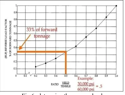
negative tonnage. The second method is to estimate the negative tonnage using the Reverse Load Factor (RLF) developed by W-Technologies, Inc. (refer to Figure 6).
Fig 6- determine the reverse load
In order to approximate the reverse tonnage generated, a large number of empirical tests were conducted to create the graph of reverse load as a function of the yield to tensile strength ratio illustrated in Figure 6. It illustrates the strong relationship that the yield to tensile strength parameter plays in the determination of reverse load. A material corresponding to low carbon mild steel sheet stock with yield strength of 30,000 psi and a tensile strength of 60,000 psi results in a yield to tensile strength ratio of .5. Selecting the .5 value on the X ordinate and the corresponding reverse load factor on the Y ordinate of .33 is established. After estimating the forward tonnage by Figure 6 the reverse load can be estimated by applying the reverse load factor and multiplying it by the estimated forward tonnage.
3.4.3 Damper Placement Determination
Determining the quantity and placement of dampers is typically determined by what space is available. The ideal set up is to use a damper in each corner of the bed (4 totals). Another option includes placing one damper on each end of the press left to right or front to back (2 totals). The last option, which is not used very often, is to place one damper in the back corner and placing the second damper on the front corner on the opposite end of the press bed.
3.4.4 Select Damper Size Determination
=
4 2 ×
= ( )
2000 A= Piston Area of Damper in Square Inches
P=Internal Design Pressure in Square Inches
IV. LOOK FOR IN A DAMPING CYLINDER
Easy set up is the key to the successful use of hydraulic shock dampers. Setting up hydraulic shock dampers is no more difficult than setting up the tooling inside of a press. Unfortunately it is too often the case that tools get bottomed (over stroked) and damaged, therefore improperly set up dampers are bottomed and damaged. Because of this, every effort must be made for quick and easy fail-safe set up procedures. External access to internal orifices for quick and easy set up adjustments is essential. If the dampers require disassembly in order to change internal orifices they are quickly discarded and are perceived to be a faulty product. Therefore, always confirm adjustability. Hydraulic shock dampers should have the ability to monitor the internal pressure and temperature. Monitoring the internal pressure will confirm if the dampers are performing to their capacity. A temperature gauge is only necessary during high-speed application. As discussed earlier, seals are greatly affected by heat. Knowing the operation temperature of the dampers will give clues to the potential seal life or will indicate that a cooling circuit is required. Use off the shelf seals and components are desirable for easy maintenance. A basic hydraulic shock damper is constructed to last indefinitely, only the seals and orifices should wear. Using off the shelf components limits the maintenance cost as well as down time. A safety pressure relief system should be designed into the hydraulic shock damper. Every damper will be designed to a pressure rating (2500 psi to 5000 psi). A relief valve will ensure that the damper cannot be over pressured.
V. CONCLUSION
Hydraulic shock dampers have proved to be cost effective way to minimize break through shock and reduce on-going press mechanical and hydraulic failures. Tooling wear will be greatly reduced, along with the noise and vibrations. Dampers work equally in hydraulic and mechanical presses. They are easily retrofit-able and mobile for quick die changes. All other options require a great deal of additional press mass or tooling cost. As manufacturers continue to move toward lighter weight, stronger material where the material yield strength approaches the tensile strength, the blanking industries will continue to push press capacity beyond their design limits. Hydraulic shock damping solves this problem.
REFERENCES
[1]Stamping Die Maintenance and Trouble Shooting by: Smith & Associates 530 Hollywood Drive Monroe, MI 48162 Author: David Smith, President
[2] High Performance Hydraulic Cartridge Valves and Manifold Systems 1995 by: Hydraforce, Inc. 500 Barclay Boulevard Lincolnshire, IL 60069
[3] Parker Packing Division 2220 South 3600 West Salt Lake City, UT 84119 High Performance Seals and Sealing Compounds
[4] Optimizing Your Diesetting Process (An introduction to reducing diesetting changeover time). by: Smith & Associates 530 Hollywood Drive Monroe, MI 48162 Author: David Smith, President
[5] ASM International, ―Forming and Forging‖, ASM Handbook Committee, Vol-14, ISBN 0-87170- 007-7 (v. 1), 1996
[6] Sneha S Pawar, R.S.Dalu, ―COMPUTER ASSISTED COMPOUND DIE DESIGN: A CASE STUDY‖ International Journal of Research in Engineering and Technology, Volume: 03 Issue: 05,
[8] SoumyaSubramonian, Taylan Altan, Craig Campbell, Bogdan Ciocirlan, ―Determination of forces in high speed blanking using FEM and experiments‖, Journal of Materials Processing Technology, 2184– 2190, 2013
[9] U.P. Singh, A.H. Streppel and H.J.J. Kals
―Design study of the geometry of a punching/blanking tool‖, Journal of Materials Processing Technology, 33, 331-345, (1992)
[10] Emad Al-Momani, Ibrahim RawabdehEmad Al- Momani, Ibrahim Rawabdeh, ―An Application of Finite Element Method and Design of Experiments in the Optimization of Sheet Metal Blanking Process‖ Jordan Journal of Mechanical and Industrial Engineering. Volume 2, Number 1, Pages 53 -63, (Mar. 2008)
[11] RidhaHambli, ―Optimization of blanking process using neural network simulation‖, The Arabian Journal for Science and Engineering, Volume 30, (June 2005)
[12] R. Hambli, ―BLANKSOFT: a code for sheet metal blanking processes optimization‖. Journal of Materials Processing Technology, Vol. 141, 234-242, 2003
[13] R. Hambli, S. Richir, P. Crubleau, B. Taravel, ―Prediction of optimum clearance in sheet metal blanking processes‖. International Journal of Advanced Manufacturing Technology, Vol. 22, page no. 20-25, 2003