An Embedded Based Rain Detection System in
Automatic Irrigation
M.Pavithra
[1], M.Mohana Priya
[2], G.Dhivya Bharathi
[3], V.Annanayagi
[4],M.V.Keerthana
[5]PG Student, Department of IT, Vivekanandha College of Engineering For Women(Autonomous), Tiruchengode,
Namakkal, Tamilnadu, India1
UG Student, Department of ECE, Vivekanandha College of Engineering For Women(Autonomous), Tiruchengode,
Namakkal, Tamilnadu, India 2,3,4,5
ABSTRACT: In India crop production and its standard has declined due to inefficient agricultural practices. Widely accepted definition of irrigation is watering the crops to maximize the crop production. Due to many obstacles like water scarcity, inefficient irrigation practices and manual irrigation the amount of water to be supplied may get higher or lower than the requirement. The best effective way to overcome water management is Precision irrigation. It is the process of delivering high accuracy irrigation to permanent crops. To deliver high precision irrigation through automatic irrigation using wireless sensor networks. Precision irrigation in DSS(Decision Support System) plays a major role. In most of the developing countries permanent crop irrigation is the major sector in which water consumption is more. Sensors play a major role in precision irrigation. They sense, monitor and collect the signals from permanent crops. In order to toggle the automatic rotation of a DC motor a simple high gain audio amplifier circuit is designed and a modem cell phone handset is used which is permanently integrated with the PCB circuit for the triggering of automatic irrigation. In the existing system in case of any natural calamity like rigorous rainfall the system doesn’t mention any prediction module. This paper proposes a solution for flood detection using water level sensor and an rain sensor to detect unpredicted rainfall management. It will support for improvement of economically weaker sections, small and marginal farmers.
KEYWORDS: High precision irrigation, wireless sensor networks(WSN), DSS(decision support system), printed circuit board(PCB), DC motor.
I.INTRODUCTION
temperature,… and other leaf based parameter like crop water stress index, pH,…both measuring and watering are controlled by the automatic irrigation system to provide an efficient crop production
[16]
II.EXISTING WORK
In the existing precision irrigation system from the poly bag of crop the sensor sense the humidity, pH, ambient temperature of the plant after that that signals are transferred through actuators to the remote server. In the remote server there exist a pre-calculated threshold value.
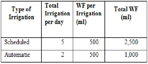
This pre-calculated threshold value (in VWC) is then compared with the current threshold value if the current VWC is less than the pre-calculated one then the automatic irrigation is triggered[5].Tropical season scheduled irrigation is triggered[3].When comparing with scheduled automatic irrigation is the best water saver.
Table I Water consumption: Scheduled Vs Automatic
III.PROPOSED WORK
The threshold value determines the triggering of automatic irrigation (i.e) whether the system should initiate or not. If the current VWC(Volumetric Water Content) is less than the pre-calculated threshold value(in VWC) then the system initiates automatic irrigation. The main drawback in existing system is the system does not provide any notification in case of any natural calamity. In order to overcome that module, in our work we had added a water sensor module which sends notification if the current VWC is in a extreme range(<40 VWC) while comparing with pre-calculated threshold value means it will be notified as disaster. Therefore the complete precision irrigation cycle depends on the pre-calculated threshold value. This project mainly focus on obtaining a high precision automatic irrigation.
The additional module is to identify the unpredicted rainfall for that a rain sensor is placed on the surface level of the crop. The rain sensor is then connected to a water conservation device. The most prominently using conservation device is hygroscopic disk. The disk is connected to the pipe valve of the tank if the sensor senses the rainfall the disk will release a electrical switch which close the gate valve of the pipe. Until or unless the farming area get dry.
In order to implement the above mentioned automatic irrigation two modules are going to be designed. One is sensor module and another one is automatic irrigation module.
SOIL MOISTURE SENSOR
In the agricultural field one of the difficult thing to define is soil moisture. For ex: The range of soil moisture differs from one user to another. If the end-user will be a farmer means he have to know about both the “surface and root zone” soil moisture. Surface soil moisture rage between 8-10cm of soil whereas root zone soil moisture range between 180-200 cm of soil. Not only in the field of agriculture it is also used in weather forecasting, water resource management.
Soil moisture is one of the important key parameter in agriculture for controlling the exchange of water and heat energy between the land and the atmosphere through evaporation and plant transpiration process. As we mentioned earlier there exist two soil moisture region one is at the surface and another one is in the root zone. Now a days the surface layer of the soil moisture is efficiently calculated using quantitative measurement of soil moisture in the top few centimeters of soil can be detected using passive remote sensing[4].whereas root zone soil moisture is difficult to detect and algorithm development for this case is very complicated because of its surface roughness, vegetation correction,…Apart from the soil moisture zones there are two methods for soil moisture measurement methods they are contact-based and contact-free methods. Contact-based methods require direct contact with the soil. Examples of contact methods include capacitance sensors [6, 7, 8], heat pulse sensors [9] and fiber optic sensors [10,11]. The second category consists of contact free measurement techniques. Remote sensing methods are prominent in this category. Remote sensing methods include passive microwave radiometers [12], synthetic aperture radars [13], and thermal methods [14,15]. Limitations of current remote sensing methods are problems with spatial averaging and a small penetration depth. These limitations make it difficult to obtain accurate values of soil moisture at a much smaller spatial support than the observation, and to sense moisture variations beyond a thin surface layer[4].
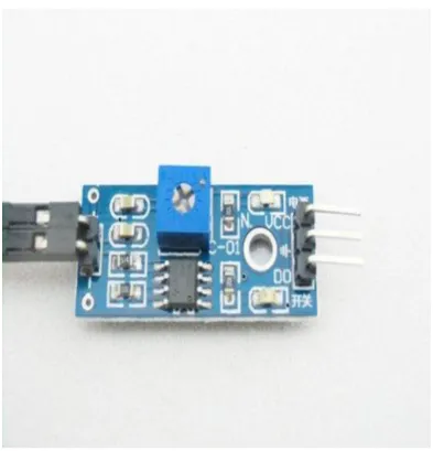
Fig 4. Moisture sensor Grove
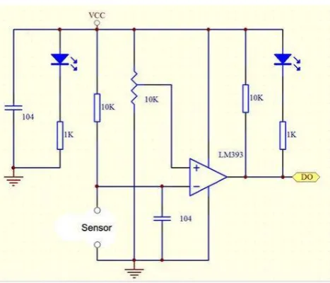
Fig 5. Moisture sensor circuit diagram
1. Operating voltage 3.3V-5V. 2. PCB size: 3cm * 1.6cm
3. Comparator LM393 chip, stable
Interface Description (4-wire) 1. VCC: .3 V-5V
2. GND: GND
3. DO: digital output interface (0 and 1) 4. AO: Analog Output Interface
RAIN SENSOR
Rain sensor is employed in 2 major areas. One is in irrigation and another one is for automobiles. For irrigation purpose both wired and wireless versions are available. In the event of rainfall a hygroscopic disk will swell and it shrink back down again as they dry out. An electrical switch is in turn released and depressed by the hygroscopic disk which shut down the system in the event of rainfall. Some mechanism were applied for both wired and wireless versions. The electrical switch were connected to the irrigation controller’s sensor terminal, which prevents the opening of any valve when rain has been sensed. In some irrigation sensor(rain) there is an freezing sensor which keeps the system from operating in freezing temperature particularly when irrigation system are used over winter season.
This module allows you measure moisture via analog output pins and it provides a digital output when a threshold of moisture is exceeded. The module is based on the LM393 op amp .It includes the electronics module and a printed circuit board that “collects” the rain drops. As rain drops are collected on the circuit board, they create paths of parallel resistance that are measured via the op amp. The lower the resistance (or the more water), the lower the voltage output. Conversely, the less water, the greater the output voltage on the analog pin[17].
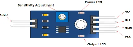
Fig 6.Rain Sensor
1. Receiver power: 22-28 V ac/V dc, 100mA (to be used with Class 2
2. UL-approved (transformer)
3. Load rating: normally open or normally closed -3A @ 24 V ac .
4. UL Listed, FCC, CE, IC
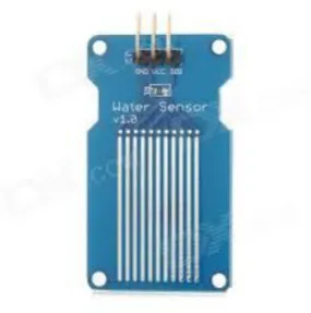
WATER LEVEL SENSORS
Fig 7.Water Level Sensor
1. Float switch
2. 10 K Ohm current-limiting resistor for float switch 3. Resistive moisture ("raindrop") sensor(s)
4. Comparators if desired (my sensors came with LM393). 5. . 10K worked for me.
MODULE II
IRRIGATIONMODULE
In irrigation module there occurs a DC motor, relay, PCB, Modem cell phone handset.
RELAY
A relay is an electrically operated switch. Many relays use an electromagnet to mechanically operate a switch, but other operating principles are also used, such as solid-state relays. Relays are used where it is necessary to control a circuit by a low-power signal (with complete electrical isolation between control and controlled circuits), or where several circuits must be controlled by one signal. The first relays were used in long distance telegraph circuits as amplifiers: they repeated the signal coming in from one circuit and re-transmitted it on another circuit. Relays were used extensively in telephone exchanges and early computers to perform logical operations. In this Paper we use two single channel 12 V relay for switching the two motors. The features are given below.
1. CONTROLLABLE with 5V or 3.3V SIGNAL
2. Equipped with high-current relay 7A@250VAC / 10A@24VDC.
3. It can be used to control both AC and DC appliances such as Solenoids, Motors , lights,….
Fig 8. Single channel 12V relay
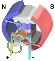
DC MOTOR
A DC motor is any of a class of electrical machines that converts direct current electrical power into mechanical power. The most common types rely on the forces produced by magnetic fields. Nearly all types of DC motors have some internal mechanism, either electromechanical or electronic, to periodically change the direction of current flow in part of the motor. Most types produce rotary motion; a linear motor directly produces force and motion in a straight line. In our system we use one dc motors which is used to supply water to the agricultural field.
Fig 9.Electric Motor
PCB
Fig 10.PCB
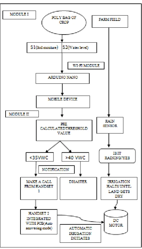
IV.SYSTEMIMPLEMENTATION
The sensors placed inside the soil sense the soil moisture and then the rain sensor , water level sensor collects the changes in the system.. From the sensor the Actuators transport the signals from sensor to the arduino board/ equivalent microcontroller platform through Wi-Fi module. A pre-calculated threshold value is already programmed in the arduino board. The value is then sent to the mobile devices using IoT communication technologies Xbee. (other technologies can also be used). If the current threshold value is less than the pre-calculated value the system ignites automatic irrigation so the water tank opens and the irrigation process starts. If the current threshold value is much more greater than the pre-calculated value it is notified as disaster. In tropical weather season scheduled irrigation will be triggered.
In order to toggle the automatic rotation of a DC motor a simple high gain audio amplifier circuit is designed and a modem cell phone handset is used which is permanently integrated with the PCBcircuit.
This circuit is used for amplifying the ringtone generated by the attached modem cell phone unit. The above mentioned modem cell phone uses a prepaid SIM and thus it becomes a self contained receiver module. When this modem cell phone is called by the owner’s cell phone, its ringtone rings then it gets amplified by the above mentioned tone amplifier and auto answering mode activated. The amplified signal becomes powerful enough to trigger the relay, and then the owner needs to press 1 in the phone pad that initiates the DC motor to start irrigate. This relay holds or remains activated as long as the water reaches the threshold value and breaks when the owner press 4 from the mobile handset. The number 1 and 4 are already integrated in the PCB. The combination can be modified in many different ways as per the users specifications.
The modem cell phone should be appropriately assigned with a particular continuous ringtone while the default ringtone should be assigned to "empty", this will make the unit immune to unknown numbers or wrong numbers, and the owner will be the sole controller of the attached circuit and the motor.
ARDUINO NANO AND WIFI MODULE
The Arduino Nano is a small, complete, and breadboard-friendly board based on the ATmega328 (Arduino Nano 3.x) or ATmega168 (Arduino Nano2.x). It has more or less the same functionality of the Arduino Duemilanove, but in a different package.
Fig 11. Arduino nano and Wi-fi module ESP826
V.CONCLUSION
Precision irrigation is designed to obtain optimization in agriculture. Using the current remote sensing technology and wireless sensor networks the resultant output will be 70-75% (approx).Sensors play a predominant role in high precision irrigation. By sensing the Soil moisture, a precision threshold value will be obtained. In order to attain precision threshold value at the time of irrigation, the wireless sensor network is used and also a modem cell phone handset is integrated with PCB to toggle the DC motor to trigger automatic irrigation. Finally this paper proposes a solution for flood detection using water level sensor and an rain sensor to detect unpredicted rainfall management. It will support for improvement of economically weaker sections, small and marginal farmers.
REFERENCES
[1] Manikantan Krishnaswamy Ramakrishna ,Priya Prakash Parab ,Puneet Girish Durve, Rahul Ashim De “ An Economical Wireless Sensor Network Based Solution for Precision Agriculture”, Capstone Research Project Proposal April 22, 2016.
[2] Hema N, Krishna Kant, “Optimization of Sensor Deployment in WSN for Precision Irrigation using Spatial Arrangement of Permanent Crop” 978-1-4799-0192-0/13/$31.00 ©2013 IEEE.
[3] Ahmad Nizar Harun, Mohamed Rawidean Mohd Kassim, Ibrahim Mat, Siti Sarah Ramli “Precision Irrigation using Wireless Sensor Network” 2015 International Conference on Smart Sensors and Application. (ICSSA) 978-1-4799-7364-4/15/$31.00 ©2015 IEEE
[4] Santosh kumar, Udaykumar R.Y, “Development of WSN System for Precision Agriculture”IEEE Sponsored 2nd International Conference on Innovations in Information Embedded and Communication Systems ICIIECS’15.
[5] Shunmin Wang, “Application of high precision accuracy irrigation based on the fuzzy spatial data mining in 4G”, Sixth International Conference on Intelligent Human-Machine Systems and Cybernetics, 978-1-4799-4955-7/14 $31.00 © 2014 IEEE DOI 10.1109/IHMSC.2014.26.
[6] Zhou, Q. Y., J. Shimada, and A. Sato, “Three-dimensional spatial and temporal monitoring of soil water content using electrical resistivity tomography”, Water Resource Res., 37, 273 – 285, 2001
[7] Michot, D., Y. Benderitter, A. Dorigny, B. Nicoullaud, D. King, and A. Tabbagh , “Spatial and temporal monitoring of soil water content with an irrigated corn crop cover using surface electrical resistivity tomography”, Water Resource Res., 39(5), 1138, 2003.
[8] Samouelian, A., I. Cousin, A. Tabbagh, A. Bruand, and G. Richard, “Electrical resistivity survey in soil science: A review”, Soil Tillage Res., 83, 173– 193, 2005.
[9] Valente, A., R. Morais, A. Tuli, J. W. Hopmans, and G. J. Kluitenberg, “Multi-functional probe for small-scale simultaneous measurements of soil thermal properties, water content, and electrical conductivity”, Sensors Actuators A, 132, 70– 77, 2006
[10] Fields, A., R. Swain, R. Kennedy, W. Belisle, T. Coleman, and A. Sharma, “Laboratory and field measurements with a fiber-optic soil moisture sensor”, Proc. SPIE 2000, 1180– 1187, 2000.
[11] Robinson, D. A., C. S. Campbell, J. W. Hopmans, B. K. Hornbuckle, S. B. Jones, R. Knight, F. Ogden, J. Selker, and O. Wendroth , “Soil moisture measurements for ecological and hydrological watershed scale observatories: A review”, Vadose Zone J., 7, 358 – 389, 2008. [12] Jackson, T. J., D. M. Levine, C. T. Swift, T. J. Schmugge, and F. R. Schiebe, “Large-area mapping of soil moisture using the ESTAR passive
microwave radiometer in Washita92”, Remote Sens. Environment, 54, 27– 37, 1995.
[13] Western, A. W., S. L. Zhou, R. B. Grayson, T. A. McMahon, G. Bloschl, and D. J. Wilson, “Spatial correlation of soil moisture in small catchments and its relationship to dominant spatial hydrological processes”, J. Hydrol., 286, 113– 134, 2004.
[14] Verstraeten, W. W., F. Veroustraete, C. J. Van der Sande, I. Grootaers, and J. Feyen, “Soil moisture retrieval using thermal inertia, determined with visible and thermal space borne data, validated for European forests”, Remote Sens. Environment, 101, 299 – 314, 2006.
[15] Sugiura, R., N. Noguchi, and K. Ishii, “Correction of low-altitude thermal images applied to estimating soil water status”, Biosyst. Engineering, 96, 301– 313, 2007.