Replacement of Grid Coupling with Bush Pin
Coupling in Blower
Ramees Rahman A1, Dr S Sankar2 Dr K S Senthil Kumar3
P.G. Student, Department of Mechanical Engineering, NCERC, Thrissure, Kerala, India1
Head of the Department, Department of Mechanical Engineering, NCERC, Thrissure, Kerala, India2
Head of the Department, Department of Automobile Engineering, NCERC, Thrissure, Kerala, India3
ABSTRACT: Couplings are used to connect the driving shaft to the driven shaft in rotating equipment. This direct connection will help for the transmission of power between the shafts. Grid couplings are type of coupling which is connected by means of metallic grid. This metallic grid takes up the load and will breaks down on overload conditions and misalignment conditions. Grid coupling will take up a misalignment of 3 mm, to reduce the failure rate of equipment due to the failure of grid coupling, bush pin coupling is introduced. It can take up a misalignment of 5 mm and will help in damping the vibration. All dimensions of bush pin coupling is calculated and analysed the same with ANSYS workbench 15
KEYWORDS: Coupling, Bush pin Coupling, Design and analysis
I. INTRODUCTION
A coupling is device used connect driving shaft to the driven shaftto transmit power. Coupling connects the shafts during operation. Coupling joints shaft with torque by allowing some misalignment. Or end movement or both.. Coupling used is grid coupling. Connecting two grooved discs or hub, one on the driving shaft and other on the driven side of the shaft. The teeth are cut axially around the hubs and is specially designed to suit a particular characteristics. The grooved hubs are connected together by means of flexible grid springs. The stiffness of spring is varies according to the unsupported length of each flexible span, and since this changes according to the changes in torque and vibration cycle
The work in this paper is divided in to two stages. 1) Study of failure in grid coupling 2) Design and analysis of Bush pin coupling.
II. RELATED WORK
Blowers are working 24x 7. It may have failure at any time. The main reasons for failure is failure of bearings and grid coupling. The studies have been done before for the analysis of failure in bearings and couplings. The frequent failure occurs in grid couplings. The grid coupling fails due to misalignment and over loading conditions. Vibration analysis are done to find out the points and cause of failures. As per the previous analysis done, it is found that misalignment is the root cause for coupling failure
III. STUDY ABOUT GRID COUPLING
The basic metallic coupling consist of two hubs are connected by a “serpent”- style metallic grid usually composed of all metal, they have some degree of resilience. They have two hubs with teeth. The teeth are connected by a steel grid. A cover keeps the lubrication. Grid coupling do not transmit as much power (for per the same outside diameter).. The hub is connected to the shafts and these hubs are connected together with help of metallic grid. The load affects the grid. When misalignment and overload occurs, grid fails. The load is affected on the grid and will deforms according to the intensity of load. Figure 1 (a) shows the final assembly of the grid coupling and (b) shows the parts of the grid coupling
(a) (b)
Fig.1 grid coupling (a) final assembly (b) Parts of grid coupling
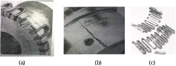
IV.FAILURESINGRIDCOUPLINGS
(a)
(b) (c)
Fig. 2 Failures in grid coupling (a) Hub tooth failure (b) Hub shank failure (c) Grid failure
V. RESULT AND SIMULATION
Blower is equipped with a grid coupling, it can only withstand a misalignment of only 3 mm. as the looseness of the foundation bolt is getting higher, and the misalignment also increases. This misalignment will affect the coupling and results in grid failure. The new coupling introduced to the system should have the capacity to withstand higher misalignment than grid couplings. Bush pin flexible coupling is desired for the replacement of grid coupling. Bush pin couplings are highly suitable for transmitting torque from one shaft to another. It is a cushion type coupling. The coupling absorb shock loads minimises tensional vibrations and accommodate slight angular and parallel misalignment.
TABLE 11.3 Comparison of couplings
Property Grid coupling Bush pin coupling
Misalignment Controlled with a grid Controlled with a pin and bush
Lubrication Vital for proper
function No lubrication Misalignment
tolerance Up to 3 mm Up to 5 mm
Fig.3 Bush pin coupling (a) Dimensions
Design calculation of coupling
The bush pin coupling for the blower is designed and the calculations are follows Power in shaft of blower =
193.2 x 10 = ∗ ∗
Torque (T) = 619 x 10 Nmm Assuming 20 % overload
T = 619 x10 x 1.2 T = 743.29x 10 Nmm Material used is mild steel (A 36), and Factor of safety 2.5
Yield strength = 237.33 N/ = (237.5/2.5)
= 94.92 N/ = /2
= 94.92/2 = 47.46 = 1.2 x = 1.2 x 94.92 = 113.90 Bearing stress ( ) =
= 23.37 N/
Keyway is provided in the shaft, so τ is considered to be decreased by 25% So
= 0.75 x = 0.75 x 47.46 = 35.959 N/
743.29
= 35.52
d = 59.6 mm
Design of pins
Standardise it to the value 80 mm
Number of pins to be added = 3/80xD + 2 = 5
Taking 8 pins for more safety and standardising it Preliminary diameter of pin d1 =
( . )
√ + 7.5
= ( . ∗ )
√ + 7.5
= 19.46 = 20mm The diameter of pin circle
= D+ 32d2
= 164 + 3.2 x 20
= 228 mm = pitch circle diameter Design of flange and hub
Material used is stainless steel (304 H)
Yield strength = 205 Mpa
= 205/3
= 68.33 N/ = 68.33/2
= 34.16 N/ = 1.2 x = 1.2 x 68.33 = 81.99 N/ = ¼ = 17.08 N/
Length of hub (L) = 1.2 x D + 20 = 1.2 x 80 + 20 = 116 mm Hub diameter (D) = 1.8 x D + 20
= 1.8 x 80 + 20 = 164 mm Flange design
Thickness (l) = .35 x D + 9 = 0.35x 80 + 9 = 37 mm
Outside diameter of flange (D2) = D1+ 6d
To withstand vibration and provide damping neoprene rubber bushes are used Thickness of rubber bush is 6 mm
Usually enlarged diameter = 1.4 d
Final diameter d2 = 1.4 x 20 + 20 + 12+4
= 64 mm
TABLE 11.4 Specification for the proposed coupling
Diameter of shaft (d) 80 mm Outer diameter of hub (D) 164 mm
Length of hub (L) 116 mm Pitch circle diameter of pins(D1) 228mm
Outer diameter of flange(D4) 284 mm
Thickness of flange(l) 37 mm Pin diameter (d1) 20 mm
Numbers of pin used 8 pins Final diameter with neoprene rubber bush (d2) 64 mm
The coupling is designed and analysed using soft wares. For design purpose CATIA V5 is used. Analysis is done by ANSYS work bench 15. The design is done as assembly drawing format. Parts are drawn in the part design section and assembled to get the final assembly design of the coupling.The analysis done is rigid dynamics, to find out what is the maximum stress occurs in the coupling, where the stress is acting and whether the coupling can withstand more misalignment than grid coupling. Analysis is done with 2980 rpm and 2800 N axial load. The model is analysed with help of Ansys workbench 15. Fine meshing is done for the analysis since it have curved surfaces. Analysis is done for 3 mm parallel misalignment.The analysis shows the coupling can withstand a stress of 648 Mpa. And the higher stress are acting on the pins of the coupling. Analysis shows that the higher stress acting is 648 MPa and grid coupling can withstand only up to 320 MPa for the same misalignment condition. So the coupling can withstand more misalignment the analysis is repeated for three times to get the consistent result.
(c) (d)
Fig. 2 Bush pin coupling (a) CATIA modelled design (b) Meshed model (c) Stress Distribution (d) Bush pin coupling
VI.CONCLUSION
The grid coupling is having higher rate of failure and it can only withstand a small misalignment. But Bush pin couplings can withstand misalignment of 5 mm. and this coupling is designed and analysed with help of ANSYS. By the analysis we found that bush pin coupling can withstand a misalignment of about 5 mm. it can withstand a stress of 648 Mpa
REFERENCES
[1] S. Maraniello, R. Palacios, “Optimal vibration control and co-design of very flexible actuated structures”, Journal of Sound and Vibration vol 377(2016) 1–21
[2] WU Xing-wei, “The Fault Diagnosis of Blower Ventilator Based-on Multi-class Support Vector Machines,” Energy Procedia vol 17 ( 2012 ) 1193 – 1200
[3] Y.Baoa, R.Palacios, M.Grahamb, S.Sherwinb “Generalized thick strip modelling for vortex-induced vibration of long flexible cylinders”, Journal of Computational Physics vol. 321 (2016) 1079–1097
[4] Min Lou, Wu-gang Wu , Peng Chen, Experimental study on vortex induced vibration of risers with fairing considering wake interference,International Journal of Naval Architecture and Ocean Engineering 20 (2016) 1-8
[5] Ashwani Kumar, Himanshu Jaiswal, Avichal Pandey, Pravin P Patil “Free Vibration Analysis of Truck Transmission Housing Based on FEA”, Procedia Materials Science vol 6 ( 2014 ) 1588 – 1592
[6]Ashwani Kumar, Himanshu jaiswal, Tarun Garg, Pravin P Patil , “Free Vibration Modes Analysis of Femur Bone Fracture Using Varying Boundary Conditions Based on FEA”, Procedia Materials Science vol.6 ( 2014 ) 1593 – 1599