Adaptive Droop DC Bus Voltage Controller
for a Grid Connected T-Source Inverter
T.Suruthimadevini1, Dr.S.Chitra2
P.G. Student, Department of EEE, Government College of Technology, Coimbatore, Tamil Nadu, India. 1
Asst. Professor, Department of EEE, Government College of Technology, Coimbatore, Tamil Nadu, India. 2
ABSTRACT: The design of the DC-bus voltage control scheme is challenging due to the presence of second harmonic ripples in grid connected inverters. PI controllers are used in the conventional voltage scheme. Though the transient performance is improved with the help of these controllers, low-frequency ripple exists in the control loop. The proposed DC-bus voltage controller is based on an adaptive droop control technique which is in conjunction with a new sampling method to calculate the mean value of the DC-bus voltage. Hence the improvement in transient response and the reduction in low-frequency ripples are possible in the proposed scheme.Also, the simple structure of the controller makes it very practical for grid connected inverters. T-source inverter has an ability to perform DC to AC conversion and buck boost operation. The reduction in number of passive elements is an advantage of T-network. To support the theoretical analysis simulation models have been developed using MATLAB (R2013a) software. The results obtained demonstrate the superior performance of the proposed control approach compared to conventional DC-bus voltage control schemes.
KEYWORDS: T-source inverter, DC-bus voltage controller, Adaptive droop control, Mean value calculator.
I. INTRODUCTION
Due to the decline of fossil fuels in the recent scenario, to meet the load requirements renewable energy plays an important role.Renewable energy is the alternate key to future global sustainability, and many endeavors are being made to harvest renewable energy in an efficient and profitable manner. Environmental concerns and reducing fossil fuel reserves increase the urgency of transitioning toward the alternate, clean renewable energies. This explains the exponential growth of wind turbine (WT) and photovoltaic (PV) usage in the past decade .However,their controllability is a great challengedue to the variable nature of the power produced by WTs and PVs makes. Thus, two main issues must be addressed in order to bring grid-connected renewable energies into the picture: cost and controllability.
II. TYPICAL POWER CONDITIONING SYSTEM
A typical power conditioning system used in renewable energy applications has two stages, and therefore it requires two separate control schemes .The first stage is called the input-side converter, and it is usually an ac/dc rectifier for
Fig.1 Power conditioning system
III. CONVENTIONAL VOLTAGE CONTROL METHOD
The voltage across the capacitor between the two stages of power conversion, known as the dc-bus capacitor, must be regulated. The dc-bus capacitor acts as an energy storage capacitor and provides the flexibility to alternate the instantaneous power in between the two stages. Thus the DC-bus capacitor gives the system, the ability to absorb sudden changes in power coming from the input-side converter. Also, in order to decouple the power ripple by providing low-frequency currentthe dc-bus capacitor is used. In conventional DC-bus voltage control schemes, a very low bandwidth PI controller is used. The PI controller should have a very low bandwidth in order to prevent the low-frequency ripple from propagating to the control loop through the dc-bus voltage feedback. Therefore, the conventional DC- bus voltage controller produces a very sluggish and poor transient response. Figure 2 shows the conventional voltage control scheme which consists of the inner current and outer voltage loops. PI controllers are used.
Fig.2. Conventional voltage control scheme
IV. PROPOSED SYSTEM
Fig.3 Block diagram of the proposed system
In future, the world anticipates to develop more of its solar resource potential as an alternative energy source to overcome the continued shortages and the unreliability in the power supply. In order to maximize the power output the system components of the photovoltaic system should be optimized. For the optimization maximum power point tracking (MPPT) is an excellent technique that grid tie inverters, solar battery chargers and similar devices use to get the maximum power that is available from one or more solar panels. Among the different methods used for tracking the maximum power point, Perturb and Observe method is an important strategy to optimize the power output of an array. In this method, the controller adjusts the voltage by a small amount from the array and measures power, if the power increases, further adjustments in that direction are tried until power no longer increases.
SAZZ (Snubber Assisted Zero Voltage and Zero Current Transition) topology was proposed with the goal ofreducing switching losses in dc chopper circuits and thereby allowing for a high frequency switching. The reduction in losses is obtained by combining a conventional dc chopper topology with a snubber which is placed across the main switch and an auxiliary circuit. The snubber reduces the voltage across the main switch in the moment of turn-off where as the auxiliary circuit discharges the snubber prior to the next switching cycle. Basic circuit diagram for the uni-directional boost SAZZ topology is depicted in Figure 4.
Fig.4.SAZZ Converter topology
V. MODEL OF T-SOURCE INVERTER
Normally Z-source inverter requires two inductance and two capacitance but T-source inverter requires a very low leakage inductance transformer which should be made with high precision. In such a way, the number of passive elements is reduced because only the transformer and the capacitor are needed so that total volume of the system can be minimized. Thus, the overall cost of the system is reduced. TSI can handle shoot through states when both switches in the same phase leg are turned on. The T-network is used instead of the LC-network for boosting the output voltage by inserting shoot through states in the PWM. The operating principle of T – Source Inverter same as that of conventional ZSI. All the PWM Methods are used for controlling the T-source inverter. Here, Simple Boost Control Method is used to control the T- source inverter. TSI operate in Shoot through mode and Non shoot through mode. In shoot-through mode of operation, the output voltage is boosted.
T-source network has low reactive components compared with conventional ZSI. Due to this, the efficiency increases considerably. The equivalent circuit of T-Source inverter is shown in Figure 5.The features of T – Source inverter are Low reactive components in comparison withthe conventional Z-source inverter, Use of a common voltage source of the passive arrangement, Minimize the number of switching devices,No needs of dead time,Inductor decreases the inrush current and harmonics in the inrush current.
Fig 5. Equivalent circuit of a T-Source Inverter
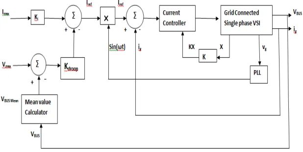
VI. ADAPTIVE DROOP VOLTAGE CONTROL METHOD
This section presents a dc-bus voltage adaptive droop control technique, which is able to regulate the dc-bus voltage to a constant value. The droop controller, in conjunction with a sensing technique known as the mean value calculator, is proposed to improve the transient response and steady-state performance of the dc-bus voltage controller for a single-phase grid-connected VSI. Figure 6 illustrates the proposed dc-bus voltage controller.
According to the figure, the mean value of the dc-bus voltage is calculated and the sensing technique is used to feed back the mean value as the dc-bus voltage. Therefore, the proposed control loop uses the mean value of the dc-bus voltage, VBUS mean, instead of the dc-bus voltage itself, V BUS.
Thus, the actual control parameter is the mean value of the dc-bus voltage given by
, , ,
The mean value calculator eliminates the double frequency ripple present at the output voltage effectively so that the feedback signal sent to the controller is the pure dc value of the dc-bus voltage. This allows the voltage controller to have a very high band-width when compared to the conventional controllers. Figure 7 shows the block diagram of the mean value calculator. According to this figure, the block makes use of the discrete value of the dc-bus voltage. Then, the ripple of the dc-bus voltage is extracted using a discrete differentiator. The signal at the output of the discrete differentiator and the double frequency ripple of the dc-bus voltage are 90◦ out of phase. Then, a comparator is used to detect the zero crossings of this signal. Based on the rising edge and falling edge of the comparator, create the sampling instants of the dc-bus voltage sample/holds.
The minimum and maximum of the dc-bus voltage values correspond to the values of the two mono-stable multi vibrators. Finally, the minimum and maximum values are used to calculatethe mean value. The mean value of the dc-bus voltage is the input to the droop controller. In the proposed droop control approach, the controller does not track a reference signal applied to the control loop. Instead, the maximum of the bus voltage is applied as the external signal to the loop and the intersection of the droop controller profile and the load profile determines the equilibrium point of the system. Thus instant action during transients, which considerably increases the speed of the control system is offered by this controller.
Fig.7 Mean Value Calculator
VII. PERFORMANCE ANALYSIS THROUGH SIMULATION
From the simulation results it can be shown that maximum power is transferred to the grid with the help of the adaptive droop voltage controller.Figure 8. shows the voltage across the DC bus capacitor
The simulation result shows that the voltage across the DC bus capacitor is available at the inverter output.Figure 9 shows the voltage output of the inverter.
Fig.9 Inverter output voltage
VIII. CONCLUSION
A novel DC-bus voltage control approach has been proposedin this paper, which is able to demonstrate a very fast and reliable performance for a single-phase grid-connected inverters. Theproposed control approach includes a new sensing techniquefor the DC-bus voltage that can effectively regulate the DC bus voltage. This controller is well-suited toward certain hybrid renewable energy applications, where a constant dc-bus voltage is required. This system minimizes the overall losses of the system and improves its efficiency. The simulation results obtained demonstrate the superior performance of the proposed control approach compared to conventional DC-bus voltage control schemes.
REFERENCES
[1] Suzan Eren,Majid Pahlevani,Alireza Bakhshai and Praveen Jain, “An Adaptive Droop DC-Bus Voltage Controller for a Grid-Connected Voltage
Source Inverter
With LCL Filter”, IEEE Trans. on Power Electronics, Vol. 30, No. 2, February 2015.
[2] S. B. Kjaer, J. K. Pedersen, and F. Blaabjerg, “A review of single-phasegrid-connected inverters for photovoltaic modules,” IEEE Trans. Ind.Appl., vol. 41, no. 5, pp. 1292–1306, Sep./Oct. 2005.
[3] M. Liserre, F. Blaabjerg, and A. Dell-Aquila, “Step-by-step design procedurefor a grid-connected three-phase PWM Voltage Source Converter,”Int. J. Electron., vol. 91, no. 8, pp. 445–460, Aug. 2004.
[4] Y.-M. Chen, C.-H. Chang, and H.-C. Wu, “DC-link capacitor selectionsfor the single-phase grid-connected PV system,” in Proc. Int. Conf. PowerElectron. Drive Syst., 2–5 Nov. 2009, pp. 72–77.
[5] X. Zong, “A single phase grid connected DC/AC inverter with reactivepower control for residential PV application,” Master’s Thesis, Univ.Toronto, Toronto, ON, Canada, 2011.
[6] Y.-H. Chang and C.-Y. Chang, "A Maximum Power Point Tracking of PVSystem by Scaling Fuzzy Control," presented at InternationalMultiConference of Engineers and Computer Scientists, Hong Kong, 2010.
[7] S.Mekhilef, "Performance of grid connected inverter with maximum power point tracker and power factor control," International Journal ofPower Electronics, vol. 1, pp. 49-62, 2008.
[8] M.E.Ahmad and S.Mekhilef, "Design and Implementation of a Multi Level Three-Phase Inverter with Less Switches and Low Output VoltageDistortation,"Journal of Power Electronics, vol. 9, pp. 594-604, 2009.
[9] S. Chin, J. Gadson, and K. Nordstrom, "Maximum Power Point Tracker," Tufts University Department of Electrical Engineering and ComputerScience, 2003, pp. 1-66.
[10] R. Faranda and S. Leva, "Energy Comparison of MPPT techniques for PV Systems," WSES Transaction on Power Systems, vol. 3, pp.446-455,2008.
[11]S. Waffler, J. W. Kolar, “A novel low-loss modulation strategy forhigh-power bi-directional buck+boost converters”, Proceedings
ofInternational Conference on Power Electronics, ICPE 2007, Oct. 2007,pp.: 889-894.
[12] W. Yu; J.S. Lai, “Ultra high efficiency bidirectional dc-dc converterwith multi-frequency pulse width modulation”, Proceedings of
AppliedPower Electronics Conference, APEC 2008, Feb. 2008, pp.: 1079-1084
[13] M. Pavlovsky, Y. Tsuruta, A. Kawamura, “Bi-directional Buck/BoostDc-Dc Converter for Electric Vehicle Propulsion with Very HighPower Density and Efficiency”, presented at Energy ConversionCongress and Exposition, ECCE 2009
[14] Y. Tsuruta, Y. Ito and A. Kawamura, “A High Frequency, HighEfficiency and High Power Chopper SAZZ and the Test Evaluation
at100kHz-8kW”, Proceeding s of Power Electronics SpecialistsConference, PESC'06, Jun 2006
and high efficiency in DC-DC converters for automotiveapplication”, Proceedings of Power Electronics Specialists Conference,PESC2008, Jun 2008, pp.: 4142 – 4148
[16] Soeren Baekhoej Kjaer, John K. Pedersen and FredeBlaabjer “AReview of Single-Phase Grid-Connected Inverters for
PhotovoltaicModules”,IEEE Transactions on Industry Applications, vol. 41,pp1292-1306 no. 5, september/october 2005.
[17] Yaosuo Xue , Liuchen Chang, Søren Bækhøj Kjær and JosepBordonauand Toshihisa Shimizu “Topologies of Single-PhaseInverters for Small
Distributed Power Generators: An Overview”IEEE Tr.3ansactions on Power Electronics, Vol. 19, pp 1305-1314No. 5, September2004.
[18] Ropp and M.E.; Gonzalez, S. “Development of aMATLAB/Simulink Model of a Single-Phase Grid-ConnectedPhotovoltaic System”,IEEE
Transactions on Energy Conversion,march 2009 page no:195-202..