Performance Comparison of Variants of Ant
Colony Optimization Technique for Online
Tuning of a Pi Controller for a Three Phase
Induction Motor Drive
Jasdeep Kour1, Sheela Tiwari2
1,2
Department of Instrumentation and Control Engineering, Dr. B.R. Ambedkar National Institute of Technology,
Jalandhar, Punjab, India
Abstract-This paper address the design and tuning schemes for a feedback controller of an induction motor drive by employing three different algorithms inspired by the behavior of the ants. A mechanical equivalent model of the drive is considered along with the parameter variations which are prominent in the system. A line of comparison is drawn between the three different algorithms discussed in the paper and the simulation results prove the superiority of the Fuzzy-Ant Colony Optimization (Fuzzy-ACO) results to the other results already reported in literature. Thus the dynamic response of the drive can be improved by tuning the controller for its optimal values by using the Fuzzy-ACO approach.
Keywords- ACO, Fuzzy System, PI Controller, Controller Tuning.
I. INTRODUCTION
Induction Motors (IM) find a widespread usage and popularity owning to its cheap and rugged structure which is realized without the use of slip rings [1]. The variable speed operation of the drive is widely needed for the numerous industrial and domestic applications and thus the speed control of the drive is essential [2]-[3]. A variety of speed control methods for the IM drive have been widely studied in literature and include Scalar Control, Vector Control, Direct and Flux Control, Sliding Mode Control and the Adaptive Control etc [4]-[6].
The Scalar Control of the drive provides a sluggish response and is easily prone to instability. This limitation of the scalar control can be overcome by employing Vector Control methods. However the Vector Control methods demand for a highly accurate mathematical model and cannot respond accurately to unknown and unavoidable variations (load variation, parameter variation due to temperature, disturbances and saturation) etc [7]-[8]. All these limitations impede for the need for a controller design and its online tuning to account for the variations in load and system parameters. Controller design and tuning can be done using Genetic algorithm, Simulation Annealing and several other techniques. In contrast to the other soft computing techniques such as Genetic algorithm (GA), Simulation Annealing (SA), the ACOs advantage lies in its multi–agent approach (distributed
calculation),positive feedback system(uses the result of the previous performances) , greedy searching and a better scalability [9]-[11]. However the design and tuning of the controller has already been reported in the literature [12] but this paper outlines three different algorithms which provide a superiority of results to the results already reported in literature [13].
A PI (Proportional Integral) controller is designed and tuned with a hybrid algorithm termed as the Ant Colony Optimization (ACO) algorithm [12]. The ACO is a heuristic algorithm inspired by the behavior of ant colonies. However the Fuzzy control is a highly effective approach to deal with the non linear, parameter varying and complex systems [14].These merits of the Fuzzy approach have been utilized for the development of the Fuzzy-ACO approach as presented in this paper.
The paper is organized as follows. Section II discusses the electrical and mechanical equivalent model of the induction motor drive while section III outlines the various steps involved in the ACO approach for the controller design of an induction motor. Section IV is devoted to the development of an algorithm for the design and tuning of a PI controller with the second variant of the ACO approach which includes the heuristic factor. Section V presents the Fuzzy- ACO approach. The simulation results and their comparison have been discussed in the section VI while section VII concludes the proposed work.
II.INDUCTION MOTOR MODEL
Induction motors also known as the asynchronous motors can be used as induction generators or can be formed in to linear induction motors which generate linear motion. The efficient dynamic performance of the drive still remains a challenging problem because of the highly non linear nature of the drive and variations in its parameters. The above reasons even compound the process of controller design.
The electrical equivalent circuit of the squirrel cage induction motor drive [15]-[16] is as shown in Fig.1. The various system equations in the synchronous or rotating frame are as given below:-
= + + (2)
0 = + − (3) 0 = + + (4) The fluxes so developed in the system are related to the
system currents as follow
=
0 0
0 0
0 0
0 0
(5)
Thus
= ∗ +
0 0
0 0
0 0
0 0
(6)
where A=
( − ) − − ( − )
−( − ) ( − ) −
( − ) −
− ( − ) − −( − )
(7)
The torque developed by the induction motor drive is given by
= − (8)
The mechanical equivalent model of the IM drive can be expressed as
+ = − (9) Where is the load torque.
Since the Stator voltage is controlled by using back to back connected SCRs configuration, so the developed torque can be expressed as
= ( , ) (10) where = firing angle of the thyristor
= rotor speed in rad./s.
Using the Taylor series and accounting for the variation in parameters, the above equation can be expressed as [12]
Δ = ∗Δ + ∗Δ (11)
where
ΔΔα
ΔΔω =
Using the above information, Eq. (9) can be expressed as
∆ + ∆ = ∆ − ∆ (12)
Fig.1Equivalent circuit of the Induction Motor in the d-q axis frame The parameter variation detoriates the dynamic performance of the drive and thus a need for the controller and its online tuning is felt. The basic schematic of the system is as shown in Fig.2 [12]. The performance of the drive is simulated using Matlab and the variation in the speed with time is as shown in Fig. 3. At some later instances, the load is introduced and the performance of the drive for the load variations is validated.However from the above simulation results it’s clear that for different operating conditions, the controller needs to be tuned individually.
The objective of the paper is to present an improved dynamic response of the drive and to facilitate the online tuning of the controller so as to account for the variations in the system parameters. The desired objective is accomplished by designing and tuning the controller with the techniques discussed in the later sections.
Fig.2. Induction Motor drive with PI Controller
Fig.3 Response of the Induction Motor drive to a step input and load
The dynamic response of the drive improves significantly and the same can be monitored in terms of the reduced value of the objective function. The objective function for the above system can be expressed as [12]
( ) = 1 + (1 + ) (13)
Subject to ≤ ≤ .
Where X is a set containing the controller gains while and represent the peak overshoot and the settling time respectively. The various steps in the algorithm are as discussed below:-
Step1: Distribute the ants randomly in the solution space Each ant in the solution space corresponds to the possible combination of the controller values.
Step2: Evaluate the value of the objective function
Considering the variations in the load and assuming a constant reference speed, the transfer function of the system can be expressed as [12]
∆ ∆
= −
+ + − +
Comparing the denominator of the above transfer function with the standard second order equation i.e.
+ 2 + = 0
2 = + −
and =
Evaluating the value of and from the above equations, we have
=
and =
Thus the peak overshoot and the settling time of the drive at different operating points can be evaluated as
=4= 4 =
Utilizing these values of the peak overshoot and the settling time, evaluate the value of the objective function corresponding to various ant locations.
Step3: Evaluate and Update the pheromone content
The pheromone at the various ant locations can be computed by the following equation
( ) = (1 − ) ∗ ( − 1) + ( )( ) (14) where ( − 1) represents the knowledge acquired from
the previous iterations about the quality of path being followed.
Step4: Evaluation of Movement Probability
The next best location that the ants can now occupy depends upon the ratio of the pheromone content at that location to the sum of the pheromone content at all other locations i.e.
=∑ (15) Higher the value of this ratio, higher is the favorability of
that path and vice-versa.
Step5: Movement of the ants
A term named Threshold probability decides the location of the ants i.e. whether the ant is in desirable region of the solution space or not. Thus for cases where
≥ (desirable region of the solution space) Co-ordinates of the new location
= ∗ ∗ , ∗ ∗ (16)
where m is the step length and is kept as a constant equal to 0.2 [12]
n = (distance between the source and the destination location) - (step length)
The multiple application of the section formula assures the movement of the ants along the resultant vector aligned at certain angles to the base vectors.
Step6: For the ants in the undesirable region of the solution space, the movement of the ants is along the centroid of the cluster formed by the ants in the desirable region of the solution space. So the new co-ordinates of the ants in this region of the solution space can be evaluated as
MOTOR DYNAMICS
DIFFERENCE
PI CONTROLLER
Δ
Δ
Co-ordinates of the new location (17) =
=
∑ ∑
.
Step7: Check if the termination criterion is reached or not. If If reached, then stop the algorithm or otherwise move to step 2.
Evaporation of the pheromone has been considered in the algorithm and is represented by .It prevents the algorithm to prematurely converge to sub–optimal points. Heuristic variable ( = ) provides a priori information about the quality of the solution i.e. the quality of movement from node i to node j[22] .The information conveyed by this factor has not been utilized in the algorithm discussed in section III and thus the ants strictly follow the higher pheromone path . The introduction of this factor improves the speed of response and thus for applications that demand a faster response, the algorithm discussed in the next section would be better than its counterpart discussed in this section.
IV. MODIFIED ACO APPROACH FOR THE CONTROLLER DESIGN
This algorithm utilizes the information conveyed by the heuristic variable as well as the pheromone content in deciding the movement of the ants. The various steps involved in this algorithm are as follow:-
Step1: Distribute the ants randomly in the solution space Each ant in the solution space corresponds to the possible combination of the controller gains that the system can adopt to yield better response.
Step2: Calculate the values of , of the system for the above ( , ) combinations. The transfer function of a three phase induction motor drive with varying load and a constant reference speed can be expressed as follow:-
∆ ∆
= −
+ + − +
Comparing the denominator of the above transfer function with the standard second order equation i.e.
+ 2 + = 0
2 = + −
and =
Evaluating the value of and from the above two equations, we have
=
and =
Thus the peak overshoot and the settling time of the drive at different operating points can be evaluated as
=4= 4 =
Utilizing these computations evaluate the value of the objective function for the various ants.
( ) = 1 + (1 + )
Step3: Evaluate and Update the pheromone content
The pheromone at the various ant locations can be computed by the following equation
( ) = (1 − ) ∗ ( − 1) +
( )( )
Where ( − 1) represents the knowledge acquired from the previous iterations about the quality of path being followed.
Step4: Apply the State Transition Rule
The next best location that the ants can now occupy depends upon the ratio of the product of the pheromone content at that location and the distance between the source and the destination location to the sum of this product evaluated at all other locations i.e.
Pm (i,j)=∑ ≠ (18)
= 0 ℎ
Higher the value of this ratio, higher is the favorability of that path and vice-versa.
Step5: Movement of the ants
The ants are moved by a step length to the location that corresponds to the maximum value of the movement probability as evaluated in step 4.
Co-ordinates of the new location
= ∗ ∗ , ∗ ∗ (19)
where m is the step length and is kept as a constant equal to 0.2
n = (distance between the source and the destination location) - (step length)
Step6: Check if the termination criterion is reached or not. If reached, then stop the algorithm or otherwise move to step 2
V. FUZZY –ACO APPROACH
The proposed approach utilizes the clustering of the agents (ants) in to two clusters namely the source and destination cluster. The clustering is done mainly to differentiate between the untuned (initial) and the tuned (final) values of the controller gains. The values in the source cluster correspond to the untuned values while the values in the destination cluster correspond to the tuned values. Corresponding to a particular value (untuned ,
values) in the source cluster, there is a value in the destination cluster that is a best fit value yielding lower values of objective function. This approach significantly reduces the response time and enhances the dynamic response of the drive.
shown in Table 1. The rule base provides with the optimized values of the controller gain in the destination cluster and all the ants are moved towards their best values in the destination cluster starting from some values in the source cluster by laying higher pheromone content along these paths.
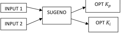
Fig. 4 Basic schematic of the Fuzzy system
TABLE 1
RULE BASE USED IN THE FUZZY-ACOALGORITHM
I/P 2 I/P 1
VSI SI MI LI VLI
SP (MP,MI) (LP,MI) (LP,LI) (VLP,VLI) (VLP,VLI) MP (LP,SI) (LP,MI) (VLP,MI) (VLP,MI) (VLP,VLI)
LP (VLP,SI) (VLP,MI) (VLP,LI) (VLP,MI) (VLP,LI)
VLP (VLP,MI) (VLP,MI) (VLP,MI) (VLP,VLI) (VLP,VLI)
The various steps involved in this algorithm are as follow:-
Step1: Distribute the ants randomly in the solution space Each ant in the solution space corresponds to the possible combination of the controller values.
Step2: Evaluate the value of the objective function
Considering the variations in the load and assuming a constant reference speed, the transfer function of the system can be expressed as
∆ ∆
= −
+ + − +
Comparing the denominator of the above transfer function with the standard second order equation i.e.
+ 2 + = 0
2 = + −
and =
Evaluating the value of and from the above equations, we have
=
and =
Thus the peak overshoot and the settling time of the drive at different operating points can be evaluated as
=4= 4
=
Utilizing these values of the peak overshoot and the settling time, evaluate the value of the objective function corresponding to various ant locations.
Step3: Form the Fuzzy rule base
The rule base for the above system is formed as shown in the Table 1.The rule base has been formed by utilizing the past experiences. The rule base divides the entire range of the controller gain values into multiple small ranges.
Step 4: Calculation of the resultant location
Utilizing the fuzzy rule base, evaluate to the next best location that the ant can occupy.
Step 5: Update the pheromone content
The pheromone at the various ant locations can be computed by the following equation
( ) = (1 − ) ∗ ( − 1) + ( )( ) Where ( − 1) represents the knowledge acquired from
the previous iterations about the quality of path being followed.
Step 6: Movement of the ants
The ants are moved by a step length towards the locations as evaluated in step 4. Thus the co-ordinates of the new location can be calculated as follow:
Co-ordinates of the new location = ∗ ∗ , ∗ ∗
where m is the step length and is kept as a constant equal to 0.2
n = (distance between the source and the destination location) - (step length)
Update the source cluster with the new values of the location co-ordinates of the ants.
Step7: Check if the termination criterion is reached or not. If reached, then stop the algorithm or otherwise move to step 2
VI. SIMULATION RESULTS AND DISCUSSIONS The comparison of the three algorithms for the controller design and tuning discussed in this paper is made for various operating points. The speed response of the drive changes with the change in the operating point or with the change in the system parameters. The performance of the three algorithms is compared in terms of the transient parameters of the system such as the peak overshoot and the settling time. The values of these transient parameters in turn are used to evaluate the numeric value of the objective function. Lower numeric values of the objective function ensure good response. Finally the percentage improvement in the dynamic response of the drive with respect to the conventional methods is discussed in Table 2. Thus from the above computations and graphical analysis it’s clear that the first and second algorithm as discussed in sections IV and V would yield same results but however vary significantly in the speed of response. INPUT 1
INPUT 2
SUGENO
OPT
The second algorithm responds faster to the variations in load or system parameters and thus significantly improves the quality of the transient response. However the Fuzzy- ACO approach yields better results than the two algorithms discussed in section IV and V and uses lesser no. of iterations as compared with the other two algorithms. The comparison of the variation in the objective function of the first and second algorithm is as shown in Fig.5. The Fig. 6 also shows efficiency of the controller designed using the Modified ACO approach and the Fuzzy-ACO approach as the controller provides the smooth tracking of the variations in the speed and load and thus provides excellent transient response at various operating points. The results so obtained in this paper provide an improved dynamic response of the drive as compared to the results already established [12].
VII. CONCLUSION
This paper outlines the importance of the controller operating at optimal conditions for producing improved dynamic response of the drive under variable conditions. The improved dynamic response is taken up as an optimization problem aiming at producing optimal controller parameters which meet the current load and voltage requirements while yielding excellent dynamic response. The optimization of the controller parameters is achieved using two variants of the ACO approach and a Fuzzy-ACO approach. The response of the drive with the second variant of the ACO approach is much faster as compared to the controller design and tuning using the first variant of the ACO approach. The smaller values of peak overshoot and settling time are possible only with the Fuzzy-ACO approach. The Fuzzy-ACO approach is thus the best possible way to design and tune the controller for a three phase induction motor drive. This approach accounts effectively for all sorts of variations without deteriorating the dynamic performance of the drive.
Fig.5 Comparison in the Variation of the Objective Function Values for First and Second Algorithm.
Fig.6 Controller tracking the variations in speed and load
TABLE 2
PERFORMANCE COMPARISON OF THREE ALGORITHMS AT VARIOUS OPERATING POINTS
CONTROLLER OPERATING
POINTS
SETTLING TIME
PEAK OVERSHOOT
VALUE OF THE OBJECTIVE
FUNCTION
PERCENTAGE IMPROVEMENT IN
PERFORMANCE PI(CONVENTIONAL)
PI(ALGO1) PI(ALGO2) PI(FUZZY-ACO)
(0.666,-2.500)
0.216 0.1900 0.1900 0.1835
0.10 0.0376 0.0376 0.0273
1.3376 1.2349 1.2349 1.2158
7.6779%
9.1058% PI(CONVENTIONAL)
PI(ALGO1) PI(ALGO2) PI(FUZZY-ACO)
(0.667,-0.667)
0.598 0.1984 0.1984 0.1913
0.116 0.0371 0.0371 0.0259
1.78337 1.2429 1.2429 1.2222
30.306105%
31.466% PI(CONVENTIONAL)
PI(ALGO1) PI(ALGO2) PI(FUZZY-ACO)
(0.372,-0.633)
0.629 0.3516 0.3516 0.3391
0.116 0.0326 0.0326 0.0141
1.81796 1.3956 1.3956 1.3580
23.2326%
25.3008% PI(CONVENTIONAL)
PI(ALGO1) PI(ALGO2) PI(FUZZY-ACO)
(0.500,-0.800)
0.499 0.2621 0.2621 0.2527
0.116 0.0353 0.0353 0.0209
1.67288 1.3066 1.3066 1.2789
21.895%
REFERENCES
[1] Bimal K. Bose, Modern Power Electronics and A.C. Drives, Third Impression, India, Pearson Education, Inc: 2007.
[2] R. Saidur, S. Mekhilef, M. B. Ali, A. Safari , H.A Mohammed , Applications of variable speed Drives (VSD) in Electric motors energy savings, Renewable and Sustainable Energy Reviews 16(2012) 543-550.
[3] ABB: A Guide to using variable speed drives and motors in hospitals and health care centers, 2010.
[4] Prof. H. Chouhan, R. Kumawat, Dr. H.K Verma , Comparative Analysis of Scalar and Vector Control Induction Machine drives through Modeling and Simulation,IJEET,vol.3,Issue 3 July-September 2012, 39-50.
[5] Honorio , D.A., Diniz, E. C , Junior , A.B.S , Almeida, O.M , Barreto, L.H.S.C, Comparison Between Sliding Mode Control for a DSP Based Position Control Applied to Squirrel –Cage Induction Motor, 9 IEEE/IAS International Conference on Industry applications, INDUSCON-2010.
[6] P.T. Krein, F. Disilvestro, I. Kanellakopoulos , J. Locker, Comparative Analysis of Scalar and Vector Control Methods for Induction Motor, 24 Annual IEEE Conference, PESC 1993,1139-1145.
[7] A.M. Eltamaly, A.I Alolah, B.M. Badr, Fuzzy Controller for Three- Phases Induction Motor Drives , IEEE Conference on Autonomous and Intelligent Systems(AIS), June 2010, 1-6.
[8] D. Archana, K. Kalyani, B.S Prasad, Efficiency Optimization of Induction Motor Using Fuzzy Logic, ISSN,Vol.2, Issue 3 , July 2012.
[9] N. Jain, R. Gupta, G. Parmar, A Review of Soft Computing Technique for PID Controller Tuning, IJAEEE, Vol.1 No.2. [10] R .Hassan, B. Cohanim, O.D. Weck, G. Venter, A Comparison of
Particle Swarm Optimization and the Genetic Algorithms, American Institute of Aeronautics and Astronautics.
[11] B. Nagraj, Dr. N. Murugananth, A Comparative Study of PID Controller Tuning using GA, EP, PSO and ACO , IEEE 2010. [12] N. Rajasekar, K. Mohana Sundaram, Feedback Controller Design
for Variable Voltage Variable Speed Induction Motor Drive via.
Ant Colony Optimization, Applied Soft Computing 12 (2012) 2132-2136.
[13] S. Jena, K.B Mohanty ,Robust Sensorless Field Oriented Control of Induction Motor Using Sliding Mode, Annual IEEE Conference INDICON , 16-18, Dec. 2011,1-6.
[14] T.D. Dongale , S.R Jadhav, S.V. Kulkarni, T.G. kulkarni, R.R. Mudholkar, M.D. Uplane , Performance Comparison of PID and Fuzzy Control Techniques in Three Phase Induction Motor Control, Int. J. on Recent Trends in Engineering and Technology, Vol.7, No.2,March 2012.
[15] B. Ozpineci, L.M. Tolbert, Simulink Implementation of induction Machine Model-A Modular Approach, IEEE conference on Electric Machines and Drives,1-4 June 2003, Vol.2 , 728-734.
[16] Pundaleek B. H., Manish G. Rathi, Vijay Kumar M. G., Speed Control of Induction Motor: Fuzzy Logic Controller v/s PI Controller, IJCSNS, VOL.10 ,No.10, October 2010, 223-229. [17] M. Dorigo, L.M. Gambardella, Ant Colony System: , Ant Colony
System: A Cooperative Learning Approach to the Travelling Salesman Problem, IEEE Transactions on Evolutionary Computation, Vol.1, No.1, April 1997.
[18] S. Huawang, C. Huishu, Data Mining of ACO-Based Rough Sets and Applications in Construction Projects Cost Analysis, First International Workshop on Database Technology and Applications , IEEE computer Society,2009.
[19] L. E. da Silva, G. L-Torres, H. G. Martins, M. P. Coutinho, L. E. B. da Silva, J. C. Neto, An Application of ACO in System Reconfiguration , Transmission and Distribution Conference and Exposition , IEEE 2010,1-6.
[20] S.J Shyu, B.M.T Lin, P.Y Yin, Application of Ant Colony Optimization for No-wait Flow shop Scheduling Problem to Minimize the Total Competition time , Computer and Industrial engineering 47(2004), 181-193.
[21] J.F. Yan , Y. Gao, Lu Yang , Ant Colony Optimization for Wireless sensor Networks Routing , International Conference on Machine Learning and Cybernetics ,10-13 July 2011 IEEE, Vol.1 400-403. [22] Oscar Cordon, F. Herrera, Thomas Stuzle, A Review on ACO