Performance analysis of 1-bit Booth encoder and
Boothdecoder
Lakum kalpeshP
1
P
, B.H.NagparaP
2
(1) Student M.tech EC in C U Shah Engineering Collage,Kothariya,Surendranagar. (2) Assistant professor at C U Shah Engineering Collage,Kothariya,Surendranagar.
Abstract
Now a day so many new technology has been develop. Most of technologies have the main importance are related to the less Delay, less power Consumption. Most of digital processor, math processor and various scientific applications required Booth multipliers. In Booth multiplier the booth encoder and booth decoder plays an important role. It occupies most of the areas and generates the signals which are useful for generate the partial product and also convert negative number using 2’s complement by using booth decoder. So booth encoder and decoder is much better as much possible. In this paper we mainly concentrate on the delay of each signal of booth encoder and booth decoder and also the counting the number of transistors we used in booth encoder and booth decoder block. There are so many way to design and implement booth encoder and booth decoder but we have chosen the Gate Diffusion Input logic and CMOS techniques which is comparatively faster than traditional ones. Now this time is of nanometer technology so we choose 45nano-metre technology. The tool which is used is TANNER EDA version 15.
Keywords:
Booth encoder, Booth decoder, GDI logic, CMOS technique, 45nm technology,TANNER EDA simulation result
I.
INTRODUCTION:
In digital multiplication, as an first step, I needs to generate n shifted copies of the multiplicand, which may be added in the coming to the next stage. The value of the Multiplier bit determines whether the shifted copy is to be added or not. Here the Multiplier and Multiplicand are multiply with Each other. If the ith bit (0 ≤ i ≤ n −1) of the Multiplier by ‘1’, then the shifted
called partial products generation. Where the partial product bits are arranged in columns to be added in order to form the product. This process is called Product Array generation.
This method is simple one and just uses the number of AND gates simply like the binary multiplication. This method is simple but it takes more delay compared to the second method that is Booth encoding technique.
Another way to generate the partial product is due to booth algorithm. The A.D. Booth proposed Booth encoding technique for the reduction of the number of partial products. This algorithm is also called as Radix-2 Booth’s Recoding Algorithm. Here the Multiplier bits are recoded. This is based on the fact that fewer partial products are generated for groups of consecutive zeros and ones. For a group of consecutive zeros in the Multiplier there is no need to generate any new partial product. It only need to shift previously accumulated group partial product one bit position to the right for every ‘0’ in the Multiplier
The Booth decoder generates the partial product from the selector signals that they are generated in encoder block. This is the logic for the 1bit decoder that generates 1 bit of the partial product
Booth encoder and Booth decoder can be designed in many ways. Generally Booth encoder and Booth decoder designed using AND gate, inverter, XOR gate, XNOR gate etc. Each of them produces the according to their inputs.
II.
Booth encoder
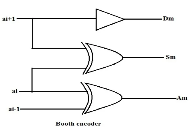
figure 1: Booth encoder
Booth encoder is the essential part of the Multiplier. It consumes much of the area of Multiplier. The booth encoder can be designed in various ways. As much as good the booth encoder the number of getting output chances good. Booth encoder is implemented with the help of inverter, XOR and AND gates. It will generate the three control signals which are given to the booth decoder for the generation of the partial product. According to the design of booth encoder and will get the output of three control signals Direction (Dm), Shift (Sm), Addition (Am)
Direction find out whether the multiplicand was positive or negative, Shift explained whether the multiplication operation include shifting or not and Addition explained whether the multiplicand was added to partial product. The expression for booth encoder as shown as below
Direction, Dm= ai+1
Shift, Sm=ai-1 AND (ai+1 XOR ai) OR ai-1’ AND (ai+1 XOR ai) = ai+1 XOR ai
Addition, Am= ai-1 XOR ai
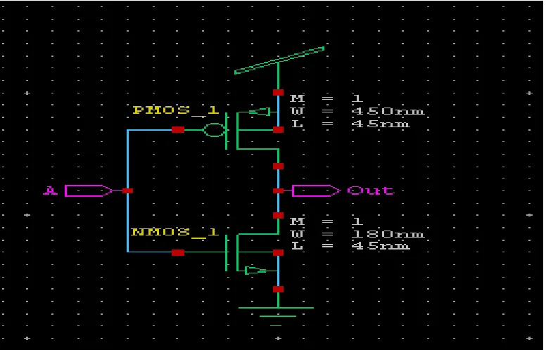
Figure 2: inverter using GDI
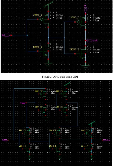
Figure 3: AND gate using GDI
Figure 4: XOR using GDI
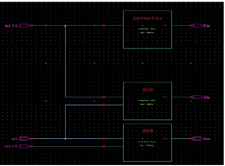
Figure 5: Booth encoder
Now according to the booth encoder we get three different signals Direction, Shift, and Addition. The truth table according to the booth encoder shown in below,
Table 1: truth table for booth encoder
ai+1 ai ai-1 Direction (Dm) Shift (Sm) Addition (Am)
0 0 0 0 0 0
0 0 1 0 0 1
0 1 0 0 1 1
0 1 1 0 1 0
1 0 0 1 1 0
1 0 1 1 1 1
1 1 0 1 0 1
1 1 1 1 0 0
III.
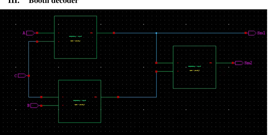
Booth decoder
Figure 6: Booth decoder
Booth encoder generates the selector signals which are given to the booth decoder. Also the Y no. of inputs are applied to the booth decoder. It can be design in number of ways. Here actually used the multiplexer for the complete designing of booth decoder. With each output generated, simultaneously one bit half adder also put in front of every output of booth decoder because of generating the partial product.
The decoder block generates the partial product from the selector signals that they are generated in encoder block. This is the logic for the 1bit decoder that generates 1 bit of the partial product:
PPG = (ai●b1●-b2+ai-1●b1●b2) xor neg
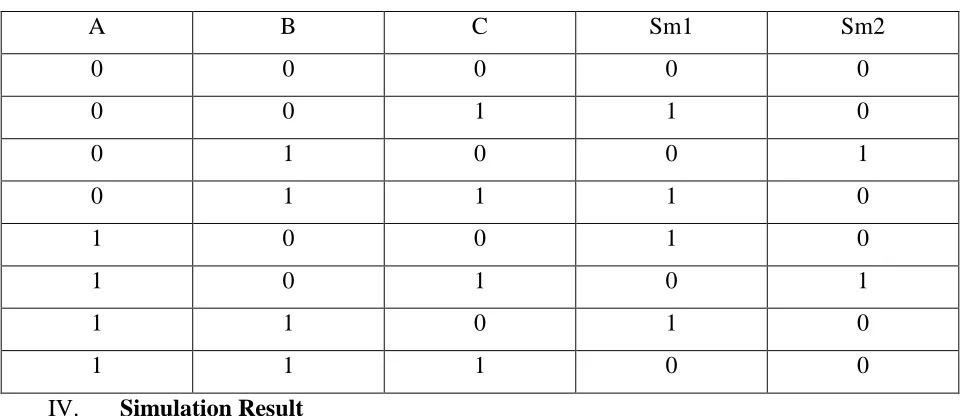
Table 2: Truth table for booth decoder
A B C Sm1 Sm2
0 0 0 0 0
0 0 1 1 0
0 1 0 0 1
0 1 1 1 0
1 0 0 1 0
1 0 1 0 1
1 1 0 1 0
1 1 1 0 0
IV. Simulation Result
As shown in figure 7 and figure 8 the transient response of booth encoder and booth decoder respectively.In wave form above three waves are indicate the input and remanding are output wave. Also table 3 indicate the analysis of booth encoder and booth decoder
Figure 7: Transient response of booth encoder
Figure 8: Transient response of booth decoder
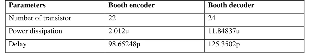
Table 3: The analysis of booth encoder and booth decoder
Parameters Booth encoder Booth decoder
Number of transistor 22 24
Power dissipation 2.012u 11.84837u
Delay 98.65248p 125.3502p
V. CONCLUSION
From the simulation of the booth encoder and booth decoder one thing is clear that booth
encoder and booth decoder gives faster result comparatively. Mainly our goal is achieved by this
method. As we can see that GDI is faster than conventional method but also improvement are
available. We show that the number of transistors is reducing using GDI technique, also reduce
the area and power dissipation as per requirement.
REFERENCES
(1) “ 1-bit Modified Booth Encoder comparative Analysis ” Shivam K Dave, prof. Bharat H Nagpara International Journal of Futuristic Science Engineering and Technology Vol 1 Issue 2 February 2013
(2) “8-Bit Radix-4 Booth Multiplier Using GDI Technique” Ankita Dhankar, Satyajit Anand International Journal of Emerging Science and Engineering (IJESE) ISSN: 2319–6378, Volume-1, Issue-6, April 2013
(3) “Radix-4 Encoder & PPG Block for Multiplier Architecture using GDI Technique” International Journal of Advanced Research in Computer Engineering & Technology (IJARCET) Volume 2, Issue 3, March 2013
(4) “AREA OPTIMIZATION OF 8-BIT MULTIPLIER USING GATE DIFFUSION INPUT LOGIC”, B.N. Manjunatha Reddy, H. N. Sheshagiri, Dr. Shanthala S. International Journal of Advanced Trends in Computer Science and Engineering, Vol.2 , No.2, Pages : 57-61 (2013)