www.euacademic.org DRJI Value: 5.9 (B+)
Elaboration of a MATLAB Script to Optimize the
Choosing Process of Earth Construction as a
Function of Soil, Climate and Average Costs
TAKANO, YOKO LUCILA1
Undergraduate student of Civil Engineering Amazonas State University, Brazil
PINHEIRO, SAMANTHA COELHO2
Doctor, Professor of Civil Engineering Amazonas State University, Brazil
PAIVA, OTÁVIO AUGUSTO3
Doctor, Professor of Civil Engineering Amazonas State University
Abstract
Earth constructions are accessible, ecological, require less energy, and use a large part of the material found in the region, about 1 to 2% when compared to ordinary masonry constructions, which also generate high amounts of solid, liquid and gaseous waste. They are also widely used today, approximately 1/3 of the population lives in this type of residence. Because of the importance of earth constructions, this article will present a script, written in MATLAB software, to optimize the user's choice of the construction types to be used, in addition to offering the amount of material and average costs.
1 Undergraduate student in Civil Engineering at the State University of Amazonas. Member of the Urutau
Aerodesign extension project, participating in the SAE BRASIL Aerodesign competition in the years 2016 to 2018, winners in third place in the Advanced category. Participant in the How to Build My Own Home extension project, aiming to instruct the community with practical and theoretical classes. Research interests in the areas of aeronautical stability and control; and structures and materials in civil engineering. Corresponding author: [email protected]
2 Doctorate in Civil Engineering with an emphasis on structures and materials from the Federal University of Rio de
Janeiro (COPPE/UFRJ). Research assistant at the Center for Sustainable Materials and Technologies (NUMATS), linked to the COPPETEC Foundation. Currently a professor at the State University of Amazonas. Works in the field of unconventional construction systems and construction materials, mineral additions for cementitious materials with a focus on physical-chemical, micro and nanostructural characterization, dosage and analysis of pastes for oil wells and durability analysis of concrete.Contact Information:[email protected]
3 Professor at the State University of Amazonas, in the Civil Engineering course in teaching and research activities
Therefore, with information on the soil type and perimeter of the house, the user will be able to know how much clay, sand, lime, among other materials, are necessary depending on the construction system analyzed. The calculation follows the one proposed by the bibliographies, from the thickness of the internal and external wall, the proportion of the soil granulometry, among other pertinent points. The constructions incorporated into the script were: rammed earth, superadobe, straw bales, poured earth, COB, and adobe. As a result, this research contributed to the creation of a simple tool to systematize the average costs and materials for earth construction.
Key words: Earth Construction, Superadobe, Adobe, MATLAB, Script.
INTRODUCTION
MATERIAL AND METHODS
Next, the calculation method and the input data used in the MATLAB software will be presented.
1.1. Adobe
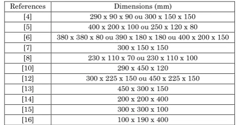
Adobe is a type of construction made with sand-clay bricks. The definition of the dimensions to be used in the script are described in Table 1.
Based on the studies by [3], based on the dimensions presented by [4], [5], [6], [7] and [8], the result was that the best size is 230x110x55 mm due to its high resistance. The thickness of the joints was defined based on the proposed by [9], which indicates the minimum value of 33 cm in thickness to have good characteristics of thermoacoustic insulation. Considering the plaster thickness of 2 cm the 230x110x55 mm block does not reach the minimum thickness value [10]. As it is not interesting internal walls with very thick thickness, therefore, for this research the dimensions of 230x110x55 mm were adopted for the internal walls.
In addition to the minimum thickness, another determining factor for the choice of dimensions for the external wall was the weight of the brick, as it is a necessary factor for the calculation of material [11]. It was then chosen the dimension 290x450x120 mm presented by [10], for providing both the weight of the brick – 21.53 kg – and its width, which, adding the 2 cm of plaster, reaches the desired 33 cm of the total thickness.
Table 1 – Brick dimensions
References Dimensions (mm)
[4] 290 x 90 x 90 ou 300 x 150 x 150
[5] 400 x 200 x 100 ou 250 x 120 x 80
[6] 380 x 380 x 80 ou 390 x 180 x 180 ou 400 x 200 x 150
[7] 300 x 150 x 150
[8] 230 x 110 x 70 ou 230 x 110 x 100
[10] 290 x 450 x 120
[12] 300 x 225 x 150 ou 450 x 225 x 150
[13] 450 x 300 x 150
[14] 200 x 200 x 400
[15] 300 x 300 x 100
Following the proposal by [9], the joints must be between 1.5 cm and 2 cm thick to avoid cracks, so the value of 1.5 cm was defined for the script. For the blocks and mortar quantity, what was proposed by [17] was followed, so the formulas below were used to quantify these materials:
(1)
(2)
Where:
= number of bricks per m2.
= volume of mortar. = brick length. = brick height. = brick width.
= horizontal mortar thickness. = vertical mortar thickness.
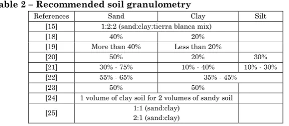
If the soil has a high concentration of clay, it will be necessary to stabilize it with sand. Cement stabilization will not be used in the script, as it has lower strength results, in addition to being an expensive stabilization method [3, 9]. Therefore, the stabilization with sand will be done with an increase of 50% for clay soils as it is an average value among those presented in Table 2. Such correction is not necessary for sandy-clay soils because they are in a similar proportion to that presented in Table 2.
Table 2 – Recommended soil granulometry
References Sand Clay Silt
[15] 1:2:2 (sand:clay:tierra blanca mix)
[18] 40% 20%
[19] More than 40% Less than 20%
[20] 50% 20% 30%
[21] 30% - 75% 10% - 40% 10% - 30%
[22] 55% - 65% 35% - 45%
[23] 50% 50%
[24] 1 volume of clay soil for 2 volumes of sandy soil
[25] 1:1 (sand:clay)
1.2. Rammed Earth
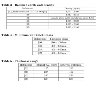
Rammed earth walls are built by hitting the moist soil between the wooden forms [26]. Therefore, wall density must be determined to calculate the amount of soil to be used. Based on the authors described in Table 3, the value of 2000 kg/m3 was chosen for being an
average value among those presented.
Concerning thickness, there are minimum values to be considered, which are shown in Table 4, in addition to having an evident variation in thickness, as shown in Table 5 [27]. Due to the thickness diversity, this value will be a data provided by the user.
At the end of the compacting, the walls have a good finish and do not need plastering, so their consideration in the script will not be made [28]. Cement stabilization will also not be used as it increases the cost of materials [29]. Therefore, stabilization by granulometric correction with the addition of 50% sand for clay-sandy soils will be used [30]. Such correction is not necessary for sandy-clay soils as they are in a similar proportion to that shown in Table 6.
Table 3 – Rammed earth wall density
References Density (kg/m3)
[27], from the data of [31], [32] and [33] 1,700 – 2,200
[29] 1.840 – 2.240
[34] Usually above 2,000 and always above 1,700
[35] 1.800 – 2,000
[36] 1.800 – 2,200
[37] 1.650 – 2,150
Table 4 – Minimum wall thicknesses
References Thickness range [30] 600 – 1000mm [36] 300 – 600mm [38] 400 – 800mm [39] 456 – 610mm
Table 5 – Thickness range
Referência Internal wall (mm) External wall (mm)
[32] 125 200
[40] 305 457
[41] 250 250
Table 6 – Recommended soil granulometry
References Sand Clay Silt
[33] 45% - 75% 0% - 20% 10% - 30%
[42] 70% - 80% 20% - 30% -
[43] 50% - 70% 5% - 15% 15% - 30%
[44] 10% - 20% 25% - 30% 50% - 80%
[45] 65% - 70% 30% - 35% -
[46] 45% - 75% 10% - 25% 15% - 30%
[47] 65% - 70% 30% - 35% -
1.3. Straw Bale
The original method of construction using straw bales is called Nebraska. This is the simplest method, in addition to requiring little prior knowledge of construction and being quite accessible [57, 58]. Next, the construction components are determined, which were divided as follows for better organization in the script, according to [57], [59], [60], and [61].
1.3.1. Straw Bales
Due to the diversity of dimensions that a bale of straw can have, as can be seen in Table 8, the dimensions will be user input. In relation to the headroom of the work, walls of a single floor or ground floor are generally six or seven bales in height and may be higher [62], however, it is important that the height to be provided by the user is a multiple of the chosen bale height, as it must not be cut – the baling is done in such a way that the straw is tied to have a good density, resulting in high strength.
Table 8 – Common dimensions of straw bales
References Straw bale dimensions
[57] 450 mm x 350 mm x 900 mm –1,125 mm
[58] 18” wide by 14” and 24” wide by 16” or 18” high – the length can vary from 32” to 40 ”
[59] 350 mm x 450 mm x 900 mm
[63] 450 mm x 350 mm x 900 mm
[64] 450 mm x 500 mm x 1.000 mm
[65] 5.5: 1 height to thickness ratios and 15.5: 1 length to thickness ratios (per Austin City
Code [66], Pina County Code [67] and Californian Residential Code 68])
[69] 375 mm x 500 mm x 990 mm
[70] 350 a 400 mm x 450 mm x 900 mm
1.3.1. Wood pins
in the stability and integrity of the wall [57, 71]. Both the diameter and the height of the pins will be input from the user. Such stakes were divided into two groups for the script:
Internal pins: from the third row of bales, two pins are placed per bale, with a maximum height of 2 and a half bales [71].
Base pins: pins driven into the upper and lower wooden base, also with an interval of two stakes per bale and an average height of a bale [57].
1.3.2. Top and bottom boxing
The main role of the top and bottom boxing is to apply tension to the bales of straw, compressing them. Regarding the top boxing, in addition to the role of transferring the load as uniformly as possible on the bale wall, it also ensures that the thread that will tie the structure will not cut the straw bales [59].
The boxing is composed of three components: (i) the external plates, which can be of OSB or plywood, with a thickness between 11 to 18 mm, (ii) the noggin and (iii) the timber, which can be salvaged wood, 50 mm by 100, 150 or 225 mm [57]. Because the thickness depends on the wood available on the market, this will be user input.
1.3.3. Plaster
Two types will be calculated, the lime plaster and the soil plaster. The lime plastering is done in a 1:3 ratio (hydrated lime and sand), while the other is between 1:4 to 1:2 (clay and sand). For the calculation of necessary material, the mass trace will be used [57].
The adopted densities of lime and sand will be equal to 1,600 kg/m3 [72]. The densities of predominantly clayey or sandy soil were
taken at values close to 1,200 and 1,300 kg/m3, respectively [39].
Table 9 – Recommended thicknesses
References Thickness
Amazon Nails [57] 12 – 50 mm
Searle [58] 25 – 75 mm
Sutton, Black e Walker [69] Around 35 mm Cabral, Pinto e Lima [74] 10 to 20 mm first layers
2 to 5 mm to finish
NZS 4298 [78] 25 – 75
1.3.4. Polyester Strapping
Attaching the walls with polyester ties secures that any bale that does not have a good density is compressed [60]. The calculation of the number of polyester filaments and their length will be given based on the one proposed by [60]. For the script, this calculation will be divided into three components:
Base filaments: smaller pieces of 1.5 m that will go below the wooden boxes on the floor [60].
Upper filaments: are passed over the wall, in greater lengths.
Connectors: to make the connection between the base and upper filaments.
1.4. COB
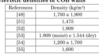
COB is a process best described as plaster of mud – soil (clay and sand) and straw [48]. The amount of soil will be calculated from the density of 1,700 kg/m3 as it is an average of the data found in the
literature, which are described in Table 7. The amount of straw will be 25 kg/m3 by the average presented by [49], which is 20 to 30 kg/m3
of fresh COB. The amount of clay and sand will be within the range of 50% to 85% sand and 50% to 15% clay – cement stabilization is not suitable for this construction [49, 50].
Table 7 – Characteristic densities of COB walls
References Density (kg/m3)
[48] 1,700 a 1,900
[51] 1,475
[52] 1,909
[53] 1.909 (moist) e 1.544 (dry) [54] 1,200 a 1,700
For [50], it is ideal to use a plaster based on soil, which is mixed with the ingredients in the same proportions as COB (clay, sand, and straw). According to [55], the plaster thickness of the COB walls should be approximately 2 cm. As the values of finished wall thickness are varied (200 to 300 mm for [51] and [54], 300 to 450 mm for [52], 600 to 900 mm for [56] and 500 to 600 mm for [49]), this data will be entered via the user's MATLAB.
1.5. Poured Earth
Poured earth is a technique cataloged within monolithic walls, capable of supporting efforts to allow the use of this as load-bearing walls [75]. [76] define poured earth as a plastic fluid containing aggregates like sand and clay. The wall is made by filling shapes in a plastic state and must not be compacted [77].
The material cost calculation will be done according to the recommended by [78], which determines the use of cement to stabilize 10% in the mixture to decrease shrinkage and increase the resistance and durability of the walls. The soil to be used must have a low clay content [78].
According to [79], the poured earth technique, in general, is not well known and there are few studies and theoretical characterizations developed, therefore, the quantification of the material will be made from the estimates, such as 1,200 and 1,500 kg/m3 for clayey and sandy soils, respectively [80]. Both for sandy and
clay soils with granulometric correction, the value of 10% cement for stabilization will be taken [78].
1.5. Superadobe
The amount of material and budget items presented by [11] will serve as a basis for defining the elements considered in the calculation of the MATLAB software. This study describes the detailed methodology for calculating the number of bags, the amount of wire, soil, among others.
RESULTS
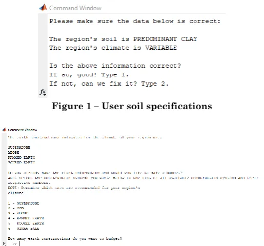
quantity and budget. The secondary auxiliary scripts 1 and 2 aim to optimize the main algorithm. The main script has the function of gathering all the other functions and compiling them as a whole. Figure 1 and Figure 2 show some interactions between the user and the algorithm, and how the user's preferences are entered.
Figure 1 – User soil specifications
Figure 2 – Choice of earth constructions to execute the budget and the quantity of material
3.1. Adobe
For the dimensioning of this system, the input values are requested to the user according to Figure 3 and the output values according to Figure 4.
Figure 4 – Output data for adobe
3.2. Rammed Earth
For the dimensioning of this system, the input values are requested to the user according to Figure 5 and the output values according to Figure 6.
Figure 5 – Input data for rammed earth
3.3. COB
For the dimensioning of this system, the input values are requested to the user according to Figure 7 and the output values according to Figure 8.
Figure 7 – Input data for COB
Figure 8 – Output data for COB
3.4. Straw Bale
Figure 9 – Input data for straw bale
Figure 11 – Output data for straw bale concerning average cost
3.5. Poured Earth
For the dimensioning of this system, the input values are requested to the user according to Figure 12 and the output values according to Figure 13.
Figure 12 – Input data for poured earth
Figure 13 – Output data for poured earth
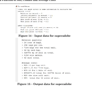
3.5. Superadobe
Figure 14 – Input data for superadobe
Figure 15 – Output data for superadobe
CONCLUSIONS
As a result, this research contributed to the creation of a simple tool to systematize the average costs and materials for earth construction. The script allows the user to obtain all proposed responses within 5 to 10 minutes. Such responses are the following:
Adobe: bricks and mortar quantity for the external and internal wall, the average price of total soil for making the bricks, plaster, and mortar.
Rammed earth: total amount and price of soil to be used for construction.
COB: amount of soil and straw for the construction of the wall and plaster, and their respective values separately.
1 plastering, quantity of soil for plastering type 2, and the total value of lime, soil, straw bales, connectors, polyester strapping needed for construction.
Poured earth: cement and soil quantity and their respective costs for the construction of the wall.
Superadobe: the total number of bags, the number of rows of bags and the number of bags per row, the amount of soil required, the number of meters of wire and the number of wire rolls, the total value for the bags, soil and wire.
All outputs include the quantity and price of sand and clay in case the granulometric correction is required, as previously presented in the materials and methods section. Therefore, it is believed that in this way there can be greater dissemination of earth constructions.
REFERENCES
1. SANTIAGO, C.C. (2001). O Solo como Material de Construção. Editora da UFBA. 2ª edição.
2. Ministério do Meio Ambiente, Construção Sustentável. Available in:
<http://www.mma.gov.br/cidades-sustentaveis/urbanismo-sustentavel/constru%C3%A7%C3%A3o-sustent%C3%A1vel>. Access in 10/04/2018.
3. A.A.R. Corrêa, V.H. Teixeira, S.P. Lopes, M.S. Oliveira. (2005). Avaliação das Propriedades Físicas e Mecânicas do Adobe.
4. A.Ortega. (2006.) Materiaux et Techniques de Construction. Bulletin du centre d’études médiévales d’Auxerre. Bucem.
5. Milanez. (1980). A Casa de Terra, as Técnicas de Estabilização do Solo a Serviço do Homem do Campo. Revista do Serviço de Patrimônio Histórico e Artístico Nacional.
6. Williams-Ellis, E. (1999). Building in Cobpise, and Stabilized Earth. Eastwick-Field. Earth Hardcover.
7. J.W. Rodrigues. A Casa de Moradia no Brasil Antigo.
8. E.C.A. Lavinsky, R.S. Serôdio, E.M. Ferreira Filho, J. Cunha. (1998). Resistência de Adobes Estabilizados com Diversos Materiais Disponíveis na Região Cacaueira da Bahia. Congresso Brasileiro de Engenharia Agrícola. 9. L. Tanaçan. (2011). Adobe Construction: A Case Study in Turkey. Faculty of
Architecture, Istanbul Technical University.
11. K. Hunter, D. Kiffmeyer. (2004). Earthbag Building: The Tools, Tricks and Techniques.
12. M.M. Rafi & S.H. Lodi, H. Varum, N. Alam & M. Ahmed, D. Silveira. (2012). Assessment of Seismic Performance of Adobe Structures in Pakistan and Portugal.
13. H. Varum, A. Costa, H. Pereira, J. Almeida. (2006.) Comportamento Estrutural de Elementos Resistentes em Alvenaria de Adobe.
14. L.A.A. Filho, S. Schumacher. (2012). Técnica de Adobe: Construção Sustentável como Evidência de Grupo Social, Religião e Cultura do Novo México
15. Dowling. (2004). Improved Adobe Mudbrick in Application – Child-Care Centre Construction in El Salvador. 13th World Conference on Earthquake Engineering.
16. B. Boudreau. (1971). Making the Adobe Brick. Fifth Street Press.
17. C. Pereira. (2019). Cálculo da Quantidade de Tijolos. Available in:<https://www.escolaengenharia.com.br/calculo-da-quantidade-de-tijolos/>. Acesso em: 09/05/2018
18. E.A. Martinez. (1979). Manual para la Construcion das Viviendas con Adobe. 19. A.T. Alves. (1985). Terra Tierra Earth Terre. Trabalho acadêmico encontrado
no Arquivo do Departamento de Materiais de Construção da Escola de Arquitetura da UFMG.
20. R. Hernandez, L. Enrique, M.L.A. Luna. (1983). A Cartilha de Pruebas de Campo para Seleccion de Tierras em la Fabricación de Adobes.
21. HB 195. (2002). The Australian Earth Building Handbook.
22. G. Barrios, L. Alvarez, H. Arcos, E. Marchant, D. Rossi. (1986). Comportamiento de los suelos para la confección de adobes.
23. Proyecto Hornero. (2007). Prototipo global de experimentación construcción con materiales naturales.
24. W. Carazas Aedo. (2002). Adobe. Guía de Construccíon Parasísmica.
25. K. Silvino, S. Chissama. (2009). Caracterização do Adobe Produzido com Solos de Camabatela e Huambo – Angola. Universidade de Aveiro.
26. L.A. Wolfskill, W.A. Dunlap, B.M. Gallaway. (1981). Handbook for Building Homes of Earth.
27. V. Maniatidis, P. Walker. (2003). A Review of Rammed Earth Construction. DTi Partners in Innovation Project, ‘Developing Rammed Earth for UK Housing’.
28. M. Dabaieh. (2014). Building with Rammed Earth. 29. H.H. DeLong. Rammed Earth Walls.
30. G. Minke. (2001). Construction Manual for Earthquake-Resistant Houses Built of Earth.
31. Standards Australia. (2002). The Australian Earth Building Handbook. 32. E.A. Adam, P.J. Jones. (1995). Thermophysical Properties of Stabilized Soil
Building Blocks. Building and Environment.
33. H. Houben, H. Guillaud. (1994). Earth Construction, A Comprehensive Guide. 34. S. Dobson. (2000). Continuity of Tradition: New Earth Buildings.
36. M. Hall, Y. Djerbib. (2003). Rammed Earth Sample Production: Context, Recommendations and Consistency. Construction and Building Materials, 2003.
37. Zhao, Y. Zhang, J. Lu. (2011). Research on Construction of Rammed Earth Buildings. Advanced Materials Research Vols.
38. C.G.S. Thaumaturgo. (2000). Conceitos e Reconceitos Relativos às Construções em Terra Crua.
39. S.K. Maiti, J.N. Mandal. (1985). Rammed Earth House Construction.
40. Tibbets, J. M. (2001). Emphasis on Rammed Earth – the rational. Interaméricas Adobe Builder.
41. NZL 4297:1998. New Zealand Standard. Engineering Design of Earth Buildings.
42. Standards Association of Zimbabwe. (2001). Rammed Earth Structures. SAZS 2001 724.
43. P.J. Alley. (1948) Rammed Earth Construction. New Zealand Engineering. 44. P.G. McHenry. (1984). Adobe and Rammed Earth Buildings. Design and
Construction.
45. J. Norton. (1986) Building with Earth: A Handbook.
46. J. Radanovic. (1996). Design Criteria for Reinforced Stabilized Earth Structures.
47. C.A. Schrader. (1981). Rammed Earth Constructions: A Re-emerging Technology.
48. T. Ley, M. Widgery. (1997). Devon Earth Building Association: COB and the Building Regulations. MCB University Press.
49. L. Keefe. (1993). The COB Building of Devon 2: Repair and Maintenance. 50. B. Bee. (1997). The COB Builders Handbook: You Can Hand-Sculpt Your Own
Home.
51. L. Miccoli, C. Ziegert, U. Mueller. (2012). Earth Block Masonry, Rammed Earth and COB: Earthen Components from Different Construction Techniques and Their Structural Performance.
52. Index and Engineering Properties of Oregon COB. (2009).
53. Q.M. Pullen. (2009). Strength and Composition of Willamette Valley COB: An Earthen Building Material.
54. L. Miccoli, U. Müller, P. Fontana. (2014). Mechanical Behavior of Earthen Materials: A Comparison Between Earth Block Masonry, Rammed Earth and COB.
55. Hamard. (2018). Rediscovering of Vernacular Adaptive Construction Strategies for Sustainable Modern Building: Application to COB and Rammed Earth.
56. L. Watson, K. McCabe. (2011). The COB Building Technique. Past, Present and Future. Informes de la Construcción.
57. Amazon Nails. (2001). Information Guide to Straw Bale Building – for Self-Builders and Construction Industries.
58. C. Searle. (2015). Straw Bale Building and the National Building Code of Canada.
61. O. Krumm, E. Cauderay, S. Fuchs. (2009). La Construction en Botte de Paille. 62. K. Henderson. (2006). Ethics, Culture and Structure in the Negotiation of
Straw Bale Buildings Code.
63. A.Rodrigues. (2015). Natural Building: The Viability of Straw Bale as a Sustainable Construction Material for the Future. Future of Architectural Research.
64. G.L.K. Garas, M.E. Allam. Straw Bale Construction as an Economic Environmental Building Alternative – A Case Study. (2009).
65. M. Faine, J. Zhang. (2000). A Pilot Study Examining the Strength, Compressibility and Serviceability of Rendered Straw Bale Wall for Two Storey Load Bearing Construction.
66. Austin City Code, Volume II. Title 25 – Land Development. Chapter 25-12 – Technical Codes. Article 1 – Uniform Building Code. Chapter 36 – Straw Bale Construction.
67. Pima County Code. (1996). Prescriptive Code for Load-Bearing and Non-Load-Bearing Straw Bale Construction as Approved by the Pima County Board of Supervisors and the Mayor and City Council of Tucson, Arizona, January 2. 68. Californian Residential Code. (2016). Part 2.5. Appendix S. Straw Bale
Construction.
69. A.Sutton, D. Black, P. Walker. (2011). Straw Bale: An Introduction to Low-Impact Building Materials.
70. P. Downton. (2013). Straw bale.
71. A.Bouter, B. King. (1994). Concervoir des Bâtiments en Bottes de Paille. 72. Densidade dos Materiais. (2018). Operaction. Available in: <
http://www.operaction.com.br/densidade-dos-materiais.>. Acesso em 23/01/2019.
73. B. King. (2006). Design of Straw Bale Buildings.
74. M.I. Cabral, C. Pinto, J. Lima. (2012). Arquitectura de Emergência: da Materialidade à Concepção Arquitectónica. Article in Revista Lusófona de Educação.
75. S. Lenci, Q. Piattoni, F. Clementi, T. Sadowski. (2011). An Experimental Study on Damage Evolution of Unfired Dry Earth Under Compression. 76. J. Cid, F.R. Mazarrón, I. Cañas. (2011). Las Normativas de Construcción con
Tierra en el Mundo.
77. J.A.E. Mujica, E.J. Suarez-Domínguez. (2016). Structural and Thermal Monitoring of Sustainable Housing with Poured Earth Walls.
78. NZS 4298 (1998). Materials and Workmanship for Earth Buildings.
79. E.J. Suarez-Domínguez, Y.G. Aranda-Jiménez, A. Palacio-Pérez, E. Izquierdo-Kulich. (2013). Modelo Matemático para La Descripción de La Transferencia del Calor para Tierra Vertida.