International Journal of Research (IJR)
e-ISSN: 2348-6848, p- ISSN: 2348-795X Volume 2, Issue 08, August 2015Available at http://internationaljournalofresearch.org
Available online:http://internationaljournalofresearch.org/ P a g e | 565
Reactive Power Compensation in Three-Phase Operation
of Micro grid
1
Rajkumar.k
PG Student ,
2
Mr. J. Rakesh Sharan
Assistant professor,Department of EEE.
Sri Indu college of Engineering and Technology, an Autonomous Institution, JNTUH, Telangana, India.
Abstract—
A coordinated control of distributed generators (DG) and distribution static compensator (DSTATCOM) in a micro grid is proposed in this paper. With high penetration of distributed sources and three-phase operation of the system, voltage unbalance can often go beyond the acceptable limit. With the feeders geographically spread out, it is not always possible to achieve reactive compensation at optimum location with the three-phase# devices. In this paper, a simple control strategy for DSTATCOM with communication in loop is proposed. The proposed reactive compensation technique is based on the voltage sag and the power flow in the line. The power flow and the voltage at different locations of the feeders are communicated to the DSTATCOM to modulate the reactive compensation. The three-phase DSTATCOM compensates for the reactive power deficiency in the phase while the DGs supply “maximum available active power.” During reactive power limit of the DG, the “maximum available active power” is fixed to a value lower than maximum active power to increase reactive power injection capability of the DGs. A primary control loop based on local measurement in the DSTATCOM always ensures a part of reactive compensation in case of communication failure. It is shown that the proposed method can always ensure to achieve acceptable voltage regulation. The data traffic analysis of the communication scheme and closed-loop simulation of power network and communication network are presented to validate the proposed method.
Index Terms—Distribution static compensator (DSTATCOM); micro grid; voltage source converter (VSC)
I. INTRODUCTION
A Micro grid is a localized grouping of electricity generation, energy storage, and loads that normally operate connected to a traditional centralized grid (macro grid) and micro grid has offered consumers with reduction in total energy losses, and with increased reliability and has become an alternative for traditional power distribution system The impact of power quality (PQ) problems on the overall power system performance depends on concepts of a micro grid distribution grid. These power quality problems dependent on some of the electrical parameters like voltage and frequency. In order to overcome power quality problems, some of power conditioning devices such as active filters, dynamic voltage restorers (DVR), uninterruptible power supplies (UPS), and several unified PQ conditioners are usually employed by users to protect their loads and systems against power quality disturbances in the overall power system. ,
International Journal of Research (IJR)
e-ISSN: 2348-6848, p- ISSN: 2348-795X Volume 2, Issue 08, August 2015Available at http://internationaljournalofresearch.org
Available online:http://internationaljournalofresearch.org/ P a g e | 566
this way, so that computational times can be reduced greatly been proposed for single phase rooftop PV grid connected system. The VSC controller is designed in taking the advantage of both current and voltage controller which is called current driven PWM based voltage controller.
Through the VSC the maximum tracked power is pumped into the grid through proper control on DC link voltage. By maintaining the DC link voltage constant during operation, is ensured the total power being generated by PV transferred across the DC bus by the inverter to the grid. Apart from active power transfer the system could be well utilized for providing limited reactive power compensation based on available capacity of the VSC. The detailed system configuration and various control schemes are briefly discussed and explained.
Installation of distributed generators (DGs) to form a micro grid can be beneficial for
both the
consumers and power utilities with local power generation [1]. The capacity of the feeders is increased with properly sited DG; however, it does not necessarily improve in system reliability or power quality (PQ) [2]. It cannot be assumed that DG automatically improves system reliability, and action may be required to ensure that reliability [2]. One of the key actions is a coordinated control of the DGs and the compensating devices. Power generation while maintaining the PQ both in grid-connected and islanded mode is the ultimate goal of such reliable micro grid. In a modern micro grid, mitigation of the PQ events can be achieved by monitoring and compensating through power electronic devices [3]. One of the major PQ problems in a micro grid with high penetration of DGs is the voltage drop. Usually, a 10% voltage drop is acceptable in a micro grid [4]. The problem of voltage regulation is also present in three-phase operation. Application of three-phase converter-based DGs is very common in a micro grid and with the increasing number of three-phase micro sources has raised concern about PQ [5]. In a low-voltage distribution network with small DGs (rooftop photovoltaic’s), voltage regulation problem exists usually at the end of the feeders [6]. However, in a micro grid, with autonomousoperations, the voltage can fall below the acceptable value in either side. Thus, an improved coordinated parallel operation of the DGs and compensating devices is essential. Several control techniques for parallel operations of the DGs to share load and control voltages in a micro grid are proposed by researchers. In [7], voltage support while sharing power through decentralized control techniques is discussed. The converter can provide active power to local loads and injects reactive power into the grid
providing voltage support at
fundamental frequency.
In [7], it is shown that the “source-following” strategy has better performances on the grid power regulation than the “grid following” strategy. In a micro grid, the converter can always be operated in droop control and mimic the synchronous machine. It is also possible to operate them in island [8]. However, in grid-connected case, the grid impedance has a strong impact on voltage source converters (VSCs) [9]. Hence, the control of the DGs needs to be modified based on grid-connected or islanded mode of the micro grid. In [10], a control strategy is proposed that is used to implement grid-connected and intentional-islanding operations of distributed power generation.
International Journal of Research (IJR)
e-ISSN: 2348-6848, p- ISSN: 2348-795X Volume 2, Issue 08, August 2015Available at http://internationaljournalofresearch.org
Available online:http://internationaljournalofresearch.org/ P a g e | 567
synchronization method for grid-connected power converters (considering other sequence components at other harmonic frequencies) is proposed in [15].
In three-phase distribution lines, many DGs are owned by the resident and operate with maximum power injections. The tariff exemption is also based on active power generation [16]. The IEEE 1547 does not allow DGs to participate in voltage regulation [17]. (“The Distributed Resources (DR) shall not actively regulate the voltage at the point of common coupling (PCC) [IEEE 1547, section 4.1.1]”.). DR systems are small scale power generation technologies used to provide an alternative or an enhancement of the traditional electric power system (EPS). Sometimes, they are connected to the grid through a power electronics interface.
Although the voltage limits at the PCC, where the area EPS is connected with a local EPS, are specified in ANSI C84.1 Range cannot participate in active voltage regulation [17]. Moreover, even with utility converter interfaced DGs, increasing the power rating of the DGs for reactive support with load growth is not always possible as that requires changes in the power electronics also (for device rating). Distribution static compensator (DSTATCOM) can provide the required voltage support and PQ improvement. In [18], a DSTATCOM is proposed to alleviate variation of both positive sequence and negative-sequence voltages at the fundamental frequency Moreover, a DSTATCOM can provide micro grid a ride through capability during transients [19]. However, the active power and reactive power in a low-voltage network are strongly coupled and regulation in voltage should consider both the real and reactive power flow [20]. An excellent study for compensation of reactive power and unbalance caused by various loads in distribution system is presented in [21].
It covers the instantaneous reactive power method with a synchronous reference frame method. PQ improvement in a four-wire electric distribution system is shown in [22]. A current-controlled voltage source inverter with a dc bus capacitor is used as a DSTATCOM. The DSTATCOM improves the supply power factor,
eliminates harmonics, provides load balancing, and improves the load terminal voltage at the PCC.The dc bus voltage of the DSTATCOM and three-phase voltages at PCC are used as feedback signals for PI controllers. The operation of DSTATCOM can be done by either voltage control or in current control mode [23]. In the voltage control mode, the DSTATCOM can force the voltage of a distribution bus to be balanced sinusoids. In the current control mode, it can cancel distortion caused by the load. In a micro grid, the DGs operate with voltage control, and to achieve reactive power coordination with the DGs, it is desirable to control the DSTATCOM in voltage control. In three-phase operation, where the feeders are geographically far apart, it is not always possible to achieve reactive compensation by three-phase device at proper location. A coordinated control of the DGs and DSTATCOM needs exchange of information and requires a communication infrastructure. Communication setup is increasingly being deployed to meet utility needs for distributed energy resources [24]. Using communication, it would be possible to improve the voltage support with DSTATCOM and DGs. The off grid renewable connection at Anyang Solar Station of South Australia [16], where three communities each with several.
Fig. 1. System under consideration
FLEXIBLE AC TRANSMISSION LINES
(FACTS) STATIC SYNCHRONOUS
SERIES COMPENSATOR (SSSC)
International Journal of Research (IJR)
e-ISSN: 2348-6848, p- ISSN: 2348-795X Volume 2, Issue 08, August 2015Available at http://internationaljournalofresearch.org
Available online:http://internationaljournalofresearch.org/ P a g e | 568
The SSSC contains a solid-state voltage source inverter connected in series with the transmission line through an insertion transformer. This connection enables the SSSC to control power flow in the line for a wide range of system conditions.
APPLICATIONS:
Static synchronous series compensator (SSSC) uses a voltage source converter to inject a controllable voltage in quadrature with the line current of a power network. Such a device is able to rapidly provide both capacitive and inductive impedance compensation independent of the power line current. Moreover, an SSSC with a suitably designed external damping controller can also be used toimprove the damping of the low-frequency power oscillations in a power network.
STATCOM
A static synchronous compensator (STATCOM), also known as a "static synchronous condenser" ("STATCON"), is a regulating device used on alternating current electricity transmission networks. It is based on a power electronics voltage-source converter and can act as either a source or sink of reactive AC power to an electricity network. If connected to a source of power it can also provide active AC power. It is a member of the FACTS family of devices. It is inherently modular and electable
.
USES
Usually a STATCOM is installed to support electricity networks that have a poor power factor and often poor voltage regulation. There are however, other uses, the most common use is for voltage stability. A STATCOM is a voltage source converter (VSC)-based device, with the voltage source behind a reactor. The voltage source is created from a DC capacitor and therefore a STATCOM has very little active power capability. However, its active power capability can be increased if a suitable energy storage device is connected across the DC capacitor. The reactive power at the terminals of the STATCOM depends on the amplitude of the voltage source. For example, if the terminal voltage of the VSC is higher than the AC voltage at the point of
connection, the STATCOM generates reactive current; on the other hand, when the amplitude of the voltage source is lower than the AC voltage, it absorbs reactive power. The response time of a STATCOM is shorter than that of an SVC, mainly due to the fast switching times provided by the IGBTs of the voltage source converter. The STATCOM also provides better reactive power support at low AC voltages than an SVC, since the reactive power from a STATCOM decreases linearly with the AC voltage (as the current can be maintained at the rated value even down to low AC voltage).
SIMILAR DEVICES:
A static VAR compensator (SVC) can also be used for voltage stability. However, a STATCOM has better characteristics than a SVC. When the system voltage drops sufficiently to force the STATCOM output current to its ceiling, its maximum reactive output current will not be affected by the voltage magnitude. Therefore, it exhibits constant current characteristics when the voltage is low under the limit. In contrast the SVC's reactive output is proportional to the square of the voltage magnitude. This makes the provided reactive power decrease rapidly when voltage decreases, thus reducing its stability. In addition, the speed of response of a STATCOM is faster than that of an SVC and the harmonic emission is lower. On the other hand STATCOMs typically exhibit higher losses and may be more expensive than SVCs, so the (older) SVC technology is still widespread.
MICROGRID SYSTEM STRUCTURE:
Fig. 1 shows the system under consideration with three feeders sections where DGs and loads are connected. The loads and DGs are suffixed with the phase it is connected with (as DG1a), to represent the first DG connected to phase a. It is assumed that the DGs are VSC interfaced. In grid-connected mode, the DGs supply the maximum power available, while the utility supplies any additional power required by the loads.
International Journal of Research (IJR)
e-ISSN: 2348-6848, p- ISSN: 2348-795X Volume 2, Issue 08, August 2015Available at http://internationaljournalofresearch.org
Available online:http://internationaljournalofresearch.org/ P a g e | 569
power demand in the islanded mode is more than the total power output of the DGs, loads are partly shaded to meet the power balance. Loads are represented by Ld1a, Ldb1, etc. The locations of the three phase compensating devices (DSTATCOM) are indicated as DSTAT a, DSTAT b, and DSTAT c. Feeder impedance is also considered. All the system parameters and DG ratings are given in Tables I–IV. The control techniques of the DGs and compensating devices are described in Sections II and III.
Table i grid and load in the micro grid
CONTROL AND COMMUNICATION
FOR REACTIVE COMPENSATION
In this section, the control and communication principle of the DGs and DSTATCOM is described. The main idea of reactive compensation in the proposed method lies in regulating compensation based on power flow and voltage in the line. In a micro grid with frequent load switching and variable DG power output, the real and reactive power flow varies in the feeders and so does the voltage. To achieve a faster control of voltage profile, it is beneficial to consider power flow in DSTATCOM control.
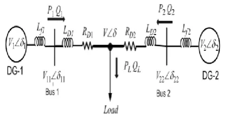
Fig. 2. Two machine system
The following is assumed.1) The DGs inject maximum available power (based on safe operating area of converter) in the
microgrid, and the reactive power generation is limited by the reactive current limit. The reactive current limit is derived from the maximum current rating and active current (d axis). The detailed converter control is described in the next section. 2) During low reactive power demand, the reactive power is shared by the DGs proportional to their rating in the islanded mode.
3) When a DG reaches the reactive power limit and the DG bus voltage goes below the voltage regulation limit, a corresponding quantity of reactive power is generated by the DSTATCOM. 4) If a DG with reactive power limit stays for five cycle, reactive power capability is increased by lowering the active power generation within a limit. 5) The possible reactive power can be generated or absorbed by the DSTATCOM is limited. This limitation is related to circuit parameter and maximum rating of the converter [4].
First, a two machine example (Fig. 2) is given to formulate the real and reactive power relations. Later a multi machine configuration is considered for reactive power compensation.
It is to be noted that these two examples are discussed to formulate the control principle for the DGs and DSTATCOM. Both the grid-connected and islanded modes of operations are considered. It is assumed that the maximum available active and reactive power of DG-1 is Preflim and Qreflim, respectively, and the voltage reference for the converter of DG-1is calculated as V1mag (The voltage reference generation for converter is shown in the next section)
The voltage reference for DG-1 converter is regulated with droop control in islanded mode [25] as
V
1ref=
V
1mag−
m
1Q1(1)
International Journal of Research (IJR)
e-ISSN: 2348-6848, p- ISSN: 2348-795X Volume 2, Issue 08, August 2015Available at http://internationaljournalofresearch.org
Available online:http://internationaljournalofresearch.org/ P a g e | 570
where η = V11/(R2D1 + X2D1). From the above
equation, multiplying Q1 by RD1 and subtracting the product from the multiplication of P1 and XD1, we get
X
D1P
1− R
D1Q
1= V
11V sin(δ11 − δ).
(2)
In a similar way, we also get
R
D1P
1+ X
D1Q
1= V
211− V V
11cos(δ11 − δ).
(3)
X
D1ΔP
1− R
D1ΔQ
1= (V
110V) (Δδ
11− Δδ) +
(δ
110V )ΔV
11(4)
R
D1ΔP
1+ X
D1ΔQ
1= (2V
110− V) ΔV
11(5)
(6)
where the impedance Z1 and the matrix K (V) aregiven by
(
7)
. (8)
(9)
It is to be noted that in grid-connected mode, the voltage drop is more at the far end of the feeder, and so the DGs at the far end are more likely to reach their reactive current limit first. The DGs near to the utility connection will supply a small amount of reactive power depending on their current rating.
In autonomous mode, the voltage in any location can fall below acceptable voltage regulation limit. However, with the DSTATCOM operation, the DGs far from DSTATCOM, on either side, may reach their reactive power limit, while the DGs close to DSTATCOM will run in proportional reactive slope within voltage regulation.
If a DG reaches the reactive power limit, it is not possible to inject more reactive power. The reactive power injected by the DSTATCOM will improve the voltage at DSTATCOM bus and also voltages in the buses adjacent to that. However, that may not have much impact on feeder location far from it. It would be beneficial to improve the voltage locally by increasing
Fig. 4. dq transformation for three phase.
(10)
International Journal of Research (IJR)
e-ISSN: 2348-6848, p- ISSN: 2348-795X Volume 2, Issue 08, August 2015Available at http://internationaljournalofresearch.org
Available online:http://internationaljournalofresearch.org/ P a g e | 571
where, imax is the maximum converter current rating and id is the d axis converter current (active power current). The reactive power reference is then generated based on the local bus voltage and this new reactive current limit.
It is evident from (10) that the relaxation of reactive current limit is more in the buses with low voltage and when the voltage is close to nominal values, the reduction in active power generation is negligible.
CONCLUSION
In this paper, a new control technique for three-phase DSTATCOM with communication is proposed. The application is aimed for microgrid feeding three-phase loads with feeder spanned geographically far apart covering small communities. The proposed reactive compensation is based on local measurement as well as the power flow in the lines. It is shown that the proposed method reduces the voltage drop more effectively while maintaining the voltage regulation with a high penetration of the DGs. Data traffic analysis for the communication setup verifies the data transfer requirement. The closed loop simulations of the power network and the communication network validate the DSTATCOM superior performances under different operating conditions.
REFERENCES
[1] X. Yoasuo, C. Liuchen, B. K. Soren, B. Josep, and S. Toshihisa, “Topologies of three-phase inverters for small distributed power generators: An overview,” IEEE Trans. Power Electron., vol. 19, no. 5, pp. 1305–1314, Sep. 2004.
[2] T. E. McDermott and R. C. Dugan, “Distributed generation impact on reliability and power quality indices,” in Proc. IEEE Rural Elect. Power Conf., 2002, pp. D3_1–D3_7.
[3] National Energy Technology Laboratory, U.S. Department of Energy, Provides Power Quality for 21st Century Needs, Jan. 2007.
[4] 978-1-84800-317-0R. Strezelecki and G. Benysek, “Active power quality controllers,” in
Power Electronic in Smart Electrical Energy Network. New York: Springer-Verlag, 2011.
[5] R. Majumder, A. Ghosh, G. Ledwich, and F. Zare, “Operation and control of three phase micro-sources in a utility connected grid,” in Proc. IEEE PES, Jul. 26–30, 2009, pp. 1–7.
[6] F. Shahnia, R. Majumder, A. Ghosh, G. Ledwich, and F. Zare, “Sensitivity analysis of voltage imbalance in distribution networks with rooftop PVs,” in Proc. IEEE Power Energy Soc. Gen. Meeting, Jul. 25–29, 2010, pp. 1–8.
[7] Z. Tao and B. Francois, “Energy management and power control of a hybrid active wind generator for distributed power generation and grid integration,” IEEE Trans. Ind. Electron., vol. 58, no. 1, pp. 95–104, Jan. 2011.
[8] Z. Qing-Chang and G.Weiss, “Synchronverters: Inverters that mimic synchronous generators,” IEEE Trans. Ind. Electron., vol. 58, no. 4, pp. 1259– 1267, Apr. 2011.
[9] Y. Shuitao, L. Qin, F. Z. Peng, and Q. Zhaoming, “A robust control scheme for grid-connected voltage-source inverters,” IEEE Trans. Ind. Electron., vol. 58, no. 1, pp. 202–212, Jan. 2011.
[10] I. J. Balaguer, L. Qin Lei, Y. Shuitao, U. Supatti, and P. Fang Zheng, “Control for grid-connected and intentional islanding operations of distributed power generation,” IEEE Trans. Ind. Electron., vol. 58, no. 1, pp. 147– 157, Jan. 2011.
[11] B.Samhita,Y.Dilip Kumar,Dr. P.H.V Sesha Talpa Sai “Investigation Of Heat Sink Capacity Of N-Heptane Fuel For Scramjet Application- ,” IJASTEMS., vol. 1, no. 2, July 2015.
International Journal of Research (IJR)
e-ISSN: 2348-6848, p- ISSN: 2348-795X Volume 2, Issue 08, August 2015Available at http://internationaljournalofresearch.org
Available online:http://internationaljournalofresearch.org/ P a g e | 572
[13] A. Vaccaro, G. Velotto, and A. F. Zobaa, “A decentralized and cooperative architecture for optimal voltage regulation in smart grids,” IEEE Trans. nd. Electron., vol. 58, no. 10, pp. 4593– 4602, Oct. 2011.
[14] T. Sauter and M. Lobashov, “End-to-end communication architecture for smart grids,” IEEE Trans. Ind. Electron., vol. 58, no. 4, pp. 1218–1228, Apr. 2011
[15] P. Rodriíguez, A. Luna, I. Candela, R. Mujal, R. Teodorescu, and F. Blaabjerg, “Multiresonant frequency-locked loop for grid synchronization of power converters under distorted grid conditions,” IEEE Trans. Ind. Electron., vol. 58, no. 1, pp. 127– 138, Jan. 2011.
[16] Clean Energy Council Australia. [Online]. Available:
http://www.cleanenergycouncil.org.au/cec/home.ht ml
[17] IEEE Application Guide for IEEE Std 1547, IEEE Standard for Interconnecting Distributed Resources With Electric Power Systems,
[18] L. Tzung-Lin, H. Shang-Hung, and C. Yu-Hung, “Design of D-STATCOM for voltage regulation in microgrids,” in Proc. IEEE ECCE, Sep. 12–16, 2010, pp. 3456–3463.
Mr. J. Rakesh Sharan received B.Tech degree in Electrical and Electronics Engineering from Asifia College of Engineering &Technology, JNTUH, and Hyderabad in 2007 and received M.Tech in Electrical Engineering from Bharat institute of Engineering and Technology, JNTUH, Hyderabad in 2011.Currently he is working as Assistant Professor at Sri Indu college of Engineering and Technology, an Autonomous Institution, JNTUH, Telangana, India.